1
Model
Series
Operator Manual
2009 Version 1.0
R.P.S. Corporation
Phone: 1-800-634-4060
Mailing: P.O. Box 368
Racine, Wi. 53401
Shipping: 1711 South st.
Racine, Wi. 53404
Fax:
1-866-901-3335
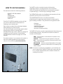
HOW TO USE THIS MANUAL
This manual contains the following sections:
- HOW TO USE THIS MANUAL
- SAFETY
- OPERATIONS
- MAINTENANCE
- PARTS LIST
The HOW TO USE THIS MANUAL section will tell
you how to find important information for
ordering correct repair parts.
Parts may be ordered from authorized dealers.
When placing an order for parts,
the machine model and machine serial number
are important. Refer to the MACHINE
INFORMATION page which is filled out during the
installation of your machine. The MACHINE
INFORMATION is located on page one of this
manual.
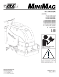
The serial number of your machine is located on
the lower steering pedestal of the steering
column of the machine. (See Picture Below)
The SAFETY section contains important information
regarding hazard or unsafe practices of the machine.
Levels of hazards are identified that could result in product
or personal injury, or severe injury resulting in death.
The OPERATIONS section is to familiarize the operator with the
operation and function of the machine.
The MAINTENANCE section contains preventative
maintenance to keep the machine and its components in
good working condition. They are listed in this general order:
- Batteries
- Scrub Brushes
- Adjusting Squeegee
- Service Schedule
- Machine Trouble shooting
The PARTS LIST section contains assembled parts illustrations and
corresponding parts list. The parts lists include a number of
columns of information:
-
ITEM - column refers to the reference number on the
-
PART NO. - column lists the part number for the part.
QTY - column lists the quantity of the part used in that
-
DESCRIPTION - column is a brief description of the part.
COMMENTS - column for information not noted by the
parts illustration.
area of the machine.
other columns.
NOTE: If a service or option kit is installed on your machine, be
sure to keep the KIT INSTRUCTIONS which came with the
kit. It contains replacement part numbers needed for
ordering future parts.
STANDARD WARRANTY POLICY (RPS Corporation)
RPS Corporation warrants its machines, parts and accessories to be free of manufacturer’s
defects for the periods specified below. Warranty will be granted at the sole discretion of
RPS Corporation and is subject to final claim and parts review by R.P.S. Corporation and its
vendors. This policy is effective January 1, 2010 and is subject to change on production units
at a future date.
COVERAGE, EXCLUSIONS AND LIMITATIONS:
Coverage:
All Models sold (Sweepers, Scrubbers, Burnishers)
Parts:
36 months / 1,500 hours on “Power On” hour meter
Labor:
12 months
Travel:
3 months (150 mile maximum)
Poly Tanks: 7 Years
OEM Parts: 3 months
Validity:
Fully completed Machine Delivery Form (online or fax) is on record at RPS.
Limitation:
Warranty will begin on date of machine installation to end-user or 6 months
after shipment from RPS Corp to the distributor if unsold at that time.
This warranty includes all parts on the machine except normal wear parts. Some of these
exceptions are:
1.
Any Brooms, Brushes, Pads or Pad Drivers including Center Clip Retainers
2.
Floor Seals, Wipers, Splash Curtains, Squeegees or Gaskets.
3.
Filters, Dust Collection Bags or Screens
4.
The safety pins design to fail in shear, which are a fail-safe device
5.
Belts, Hoses or Tubing.
6.
Caster Wheels, Tires or internal tire tubes.
7.
Vacuum motors with evidence of water/foam passage or more than 450
hours
8.
Lights (Strobe, Headlights or bulbs).
9.
The Batteries (see below).
NOT COVERED: Routine maintenance, adjustments or parts damaged from
abuse, neglect, improper use of the machine, or lack of scheduled “daily,
weekly, monthly” maintenance in accordance with our published PM Sheets.
POLY TANKS: 7 Years Coverage against leakage due to manufacturer’s defect in materials or
workmanship. NOTE: Freight coverage for 3-Years under the parts section of warranty.
BATTERIES: Warranted through battery manufacturer for One (1) Year (prorated) from the date of
delivery. The battery manufacturer approves or denies the warranty coverage after analysis. We rely
on solely on their review. NOTE NOT COVERED: Damage from lack of water, failure to use OEM
charger, or non-distilled water.
Table of Contents
Machine Information
Machine delivery form
Machine specifications
Common wear parts/scrub brushes
Safety messages
!!Safety precautions!!
Machine controls and features
Lcd screen menu displays
Machine setup
Attaching squeegee
Adjusting squeegee
Leveling scrub deck
Attaching brushes
Adjusting shrouds
Adjusting cylindrical side wipers
Solution system
Vacuum system
Machine operation
Draining recovery & solution tanks
Rec. Float shut off
Drain saver
Standard battery charging
Optional battery charging
On-Board charger operator manual
Changing batteries
Side broom system
Overhead guard
HD Side doors
On-board Soap
Spray hose
Vac wand
Diffuser exhaust bar
Stainless steel recovery tank
Stainless steel solution tank
Industrial battery
Removable battery box
On-Board soap
Spray hose
Vac wand
Maintenance & storing machine
Preventative maintenance records
Troubleshooting central command ii
Troubleshooting
Page 1
Page 2
Page 3
Page 4
Page 5
Page 6
Page 7-8
Page 9
Page 10
Page 11
Page 12
Page 13
Page 14
Page 15
Page 16
Page 17
Page 18
Page 19-21
Page 22
Page 23
Page 23
Page 24
Page 25
Page 26-28
Page 29
Page 30
Page 31
Page 31
Page 31
Page 31
Page 32
Page 32
Page 32
Page 32
Page 32
Page 32
Page 33
Page 33
Page 33
Page 34-35
Page 36-37
Page 38-39
Page 40-41
Machine Information
Model number_____________________________________________________________
Serial number:______________________________________________________________
Installation date:___________________________________________________________
Installing dealer:____________________________________________________________
Dealer contact: ___________________________________________________________
Address:___________________________________________________________________
City, state, zip: _____________________________________________________________
Phone number:_____________________________________________________________
This operator and parts manual should be considered a permanent part of the unit and should
remain with the unit at all times. This operator and parts manual covers all the XR series scrubbers.
You may find descriptions and features that are not on your particular model. The information
and specifications included in this publication were in effect at the time of printing.
R.P.S. Corporation reserves the right to make changes without notice incurring any obligation.
To register for warranty, fax your warranty registration form today! Fax # (886)-632-6961
PAGE 1
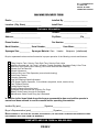
R.P.S. CORPORATION
P.O. BOX 368
RACINE, WI 53401
PHONE: 800-634-4060
MA CHINE DELIVE RY FORM
Dealer: __________________________
Installed By: ______________________
Location: (City, State)_______________
Install Date: ______________________
Customer Information
Name:________________________
Contact: _________________________
Address:_________________________
City/State:__________________Zip______
Phone Number :___________________
Fax Number: _____________________
Model Number:___________ Serial Number:______________
Squeegee Size:__________ Squeegee Material: Gum
Linatex
Hour Meter:____________
Neoprene
(circle one)
Buyer’s representative has received instruction in proper operation of the following controls and features:
Filling Solution Tank, Solution Tank Sight Tube, Solution Drain Valve
Adjusting Controls and “Uni-Touch” operation, Double Scrubbing, Squeegee Delay & Vac Timer
Recovery Tank Draining and Cleaning, Vac Screen Removal and Cleaning
Shroud and Pad Removal
Shroud Adjustment
Solution Valve and Filter Operation (removal and cleaning)
Drain Saver Feature
Charging Operation
Seat and Steering Wheel Adjustment
LCD Screen Display Operation, 3 Hour Meters (keyswitch, brush, traction drive)
Tank Tilt Back Feature
Parking Brake Override
Checking Battery Electrolyte Level
Squeegee Hose Removal and Checking For Clogs
Battery Guide Poster Hung Up & Reviewed
Maintenance Guide Poster Hung Up & Reviewed
In addition to the items listed above the buyers representative has received the operator’s
manual and been advised to read the manual before operating the machine.
Installed By (print)______________________Signature________________
Buyer’s Representative (print)_____________________Signature_______________
BUYER AGR EES TO PAY FOR ANY REPAIRS, ADJUSTMENTS, OR SECONDARY TR AIN ING THAT MANUFACTURER
DETERMINES IS EXCLUDED FROM THE WARRANTY
COMPLETE AND FAX FORM to 866-632-6961
PAGE 2
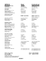
SPECS
Disk
Cylindrical
BODY CONSTRUCTION
Tank Material:
Frame Construction:
Front Wheel:
Rear Wheel:
Body Dimensions (L x W x H):
Width (squeegee):
Weight (w/out batteries):
Weight (w/ standard batteries):
(3/8”) Roto-Poly
3/16” Coated Steel
12” x 4”
(2) 14” x 5”
69” x 36” x 59”
46”, 53” or 60”
1,230 pounds
1,950 pounds
(3/8”) Roto-Poly
3/16” Coated Steel
12” x 4”
(2) 14” x 5”
69” x 36” x 59”
46”, 53” or 60”
1,230 pounds
1,950 pounds
XR-34D - (2) 17 inches
XR-40D - (2) 20 inches
BRUSH/PAD SYSTEM
Brush/Pad Diameter:
Motor Power (standard):
Brush Pressure:
Brush Pressure Settings:
Actuator Rating:
(2) 1.5 hp / 270 rpm
0-350 pounds
(1-5) automatic
500 lbs.
XR-34C - (2) 32” x 7.0”
XR-40C - (2) 42” x 7.0”
XR-46C - (2) 44” x 7.0”
(2) 1.5 hp /750 rpm
0-350 pounds
(1-5) automatic
500 lbs.
BATTERY SYSTEM
System Voltage:
Battery AH Rating (Standard):
Battery AH Rating (Optional):
Battery AH Rating (Industrial):
Battery Run Time:
Charger (110v / 60 Hz / auto):
36 volts
(6) 325 AH
(6) 395 AH
(1) 440 AH/1,280 lbs
Up to 7 hours
36-v / 36-amp
36 volts
(6) 325 AH
(6) 395 AH
(1) 440 AH/1,280 lbs
Up to 7 hours
36-v / 36-amp
SOLUTION SYSTEM
Solution Tank Capacity:
Solution Flow Rate:
Solution Filter:
68-gallons
0–1.5 gal/min.
Stainless Inline
68-gallons
0–1.5 gal/min.
Stainless Inline
RECOVERY SYSTEM
Recovery Tank Capacity:
Vacuum Horsepower:
Drain Hose:
Vacuum (Water Lift / Cubic ft/min):
Demisting Chamber:
Drain Saver:
68-gallons
1.6 hp
2.0” Diameter
68” / 140 cfm
2.5 Gallons
30 cubic inches
68-gallons
1.6 hp
2.0” Diameter
68” /140 cfm
2.5 Gallons
30 cubic inches
DRIVE SYSTEM
Standard Drive:
Speed Control:
Forward Speed:
Reverse Speed:
Minimum Aisle U-Turn:
Sound Level:
3 hp, Front Motor Wheel
Variable 0-320 ft.
0 – 320 ft/min
0 – 200 ft/min
56”
68 dBA
3 hp, Front Motor Wheel
Variable 0-320 ft.
0 – 320 ft/min
0 – 200 ft/min
56”
68 dBA
34” / 36,720 sq.feet / hour
40” / 43,200 sq.feet / hour
34” / 36,720 sq.feet / hour
40” / 43,200 sq.feet / hour
46” / 49,680 sq.feet / hour
PRODUCTIVITY
Cleaning Width & Rate/Hour:
R.P.S. Corporation
P.O. Box 368
Racine, WI 53401
Phone: (800) 634-4060
Fax: (866) 901-3335
Copyright R.P.S. Corporation 2006. All rights reserved.
Since our policy is one of constant improvement, all
specifications are subject to change without notice.
PAGE 3
Common Wear Parts
Brushes
Model
Model
Model
34"-Disk
40"-Disk
46"-Disk
Super-Grit
17-421 SS 20-421 SS 23-421 SS
Tough-Grit
17-421 S
20-421 S
23-421 S
Midi-Grit
17-421 C 20-421 C 23-421 C
Light-Grit
17-421 PS 20-421 PS 23-421 PS
Poly (.028)
17-421 P
20-421 P
23-421 P
Nylon (.016)
17-421 N 20-421 N
23-421 N
Tampico
17-421 T
20-421 T
23-421 T
Pad Driver
17-421 D 20-421 D
23-421 D
Diamond Driver 17-421 DD 20-421 DD 23-421 DD
NOTE: # In Disk Column Denotes Pad Size: 17,20, 23
Pads
Super-Black
Black
Brown
Green
Blue
Red
White
Brush repair kit: 40-423 Replacement locating clip for all brushes.
Brushes
Super-Grit
Tough-Grit
Midi-Grit
Light-Grit
Poly (.028)
Nylon (.016)
Disk
Level
##-422 BB Very High
##-422 B
High
##-422 BR
High
##-422 G Medium
##-422 BL Moderate
##-422 R Moderate
##-422 W
Light
Color
Black
Black
Brown
Green
Blue
Red
White
Extra pad driver retaining clip: 40-433
Model
Model
Model
34"-Cyl
40"-Cyl
46"-Cyl
N/A
N/A
N/A
327-821S 387-821S 447-821S
327-821C 387-821C 447-821C
327-821PS 387-821PS 447-821PS
N/A
N/A
N/A
327-821N 387-821N 447-821N
Squeegee blade kits & Complete Squeegee assemblies
Squeegee size
Model
34"-Cyl
34"-Disk
46" squeegee Optional
53" squeegee Standard
60" squeegee Optional
Model
40"-Cyl
40"-Disk
N/A
Standard
Optional
Model
46" Disk
46"- Cyl
N/A
Optional
Standard
Gum Rubber
blade kit
Linatex
blade kit
360-770 G
370-770 G
380-770 G
360-770 L
370-770 L
380-770 L
Complete
squeegee
assemblies
360-7180
370-7180
380-7180
Squeegee blade kits include (1) Rear Blade, (1) Front Blade, and (2) Backup Wheels with harware.
Squeegee Assemblies (complete) listed above all come with Linatex blades.
Size is stamped into the top of the painted steel squeegee body on all squeegee's.
The squeegee is designed for narrow isles and may not have the same water control around tight turns
as the larger squeegees.
NOTE:
NOTE:
NOTE:
NOTE:
SOAP
Heavy Duty Degreaser
Citrus
Freezer
Tire Mark Remover
For more soap information call PowerCat 414-745-9337
www.powercatsolutions.com
PAGE 4
Safety Message
Your safety, and the safety of others, is very important, and operating this unit safely is an
important responsibility.
To help you make informed decisions about safety, we have provided operating procedures
and other safety information in the manual. This information informs you of potential hazards
that could hurt you or others.
It is not practical or possible to warn you of all the hazards associated with operating this
unit. You must use your own good judgment.
This is intended for commercial use. It is designed to be used on hard floors in an indoor
environment, with the recommended pads or brushes.
1. Do not operate unit:
Unless trained and authorized.
Unless operator manual is read and understood.
If unit is not in proper operating condition.
Outdoors or exposed to rain.
For picking up hazardous materials/dust.
On surfaces having a gradient exceeding 2% unless the optional
Parking brake is functioning on the machine.
2. When operating unit:
Remove loose objects from the floor that may be projected from the
revolving brushes.
Keep hands and feet away from revolving brushes.
Do not operate machine where flammable liquids are present.
Use extreme caution when maneuvering.
3. Before leaving:
Make sure machine is turned off.
Stop on level surfaces.
Disconnect batteries.
4. Before servicing:
Stop on level surface, and secure machine.
Disconnect batteries.
5. Before discarding machine:
The batteries must be removed and properly disposed of.
PAGE 5
!! Safety Precautions!!
Warning: Hazardous voltage. Shock, burns or
electrocution can result. Always disconnect the
batteries before servicing machine.
Warning: Batteries emit hydrogen gases, explosion or
fire can result. Keep sparks and open flames away.
Warning: Charge unit in a well ventilated area, and
keep battery compartment open when charging.
Explosion or fire could result.
Warning: Always use the charger provided by the
manufacturer to charge the machine. It is an
automatic charger, specifically designed to charge
at the appropriate rate. If you must use a different
charger, disconnect the batteries before charging.
This will prevent damage to the electronic speed
controller.
Warning: Understand the dynamic braking system
before you operate the machine on ramps. Machine
does not coast. Releasing the foot pedal will
automatically apply braking force, and stop the
machine.
Warning: Battery acid can cause burns. Wear
protective eye wear and gloves when servicing
batteries.
Warning: Do not store outdoors or pressure wash.
Warning: Do not park the machine on ramps or
slopes. The machine has a parking brake, but it is
recommended that it is always parked on level
ground.
Warning: The use of parts and solutions other than
Warning: Do not operate the machine if any parts
have been removed or damaged.
Warning: Dress safely. Do not wear rings or metal wrist
Warning: Do not remove, paint over, or destroy
warning decals. If warning decals become
damaged, they must be replaced.
Prevent from getting electronic components wet.
recommended by the manufacturer may cause
damage or endanger people.
watches while working on this machine. They can
cause an electrical short, which can cause serious
burns. Do not work on this machine while wearing a
tie, scarf or other loose, dangling neckwear or
clothing. These loose items can tangle in the rotating
parts and cause serious injury or even death.
Warning: Do not operate machine in unsafe
condition. If the machine is in need of repair or is in
any way unsafe to operate, the matter should be
reported immediately to the shift supervisor. Do not
operate the machine until it is returned to proper
operating condition.
Warning: Do not use the machine as a step ladder or
chair.
Warning: This machine must only be operated by
trained operator. As part of his or her training, they
must read this manual thoroughly. If extra copies are
needed, contact your local dealer.
Warning: Only operate this machine from the
operator's seat. It was not designed to carry
passengers.
Warning: Do not operate this machine on ramps or
uneven surfaces. When climbing a ramp, always drive
the machine in forward straight up or down the ramp.
Never drive across the incline. Do not back down or
turn on ramps!
Warning: Do not attempt to push or pull the machine
without first manually overiding the parking brake and
disconnecting both leads to the traction motor.
(See page 21 for pictures)
PAGE 6
Warning: Always turn off the machine, before leaving
it unattended.
Warning: Do not operate over electrical floor outlets,
may result in serious injury.
Machine Controls and Features
7
3
1
8
9
10
11
2
12
13
14
15
16
4
5 6
25
19
20
21
17
22
23
24
18
26
27
28
38
33
39 40
29
30
41
31
32
26
48 49 50
51
56 57
58
42
37
43
46
34
35 36
PAGE 7
44
45
47
52 53 54 55
Controls and Functions
1. Steering wheel: Steers the machine.
2. Adjustable seat with arm rests: Your machine is equipped with an adjustable seat with arm rests.
3. Recovery tank lid: Latch must be secured for recovery tank to seal properly.
4. Polyurethane rollers: Helps prevent damage to machine and objects you may drive close to.
5. Adjustable disk deck side wipers: Controls water on turns by directing it to the squeegee.
6. On board charger (optional): Plugs into any three pronged 20 amp dedicated outlet to charge machine
7. Horn button: Sounds the horn for warning oncoming traffic.
8. Headlight switch: Turns headlight on and off.
9. Adjustable steering: Four settings for operator comfort and ease of entry.
10. Hour meter: Keeps track of total hours of use on the machine.
11. Battery hour meter: keeps track of total hours of use on the batteries.
12. Water control lockout: locks out the solution flow control so it cannot be changed.
13. Down pressure lockout: locks out the scrub deck down pressure so it cannot be changed.
14. Serial # plate: Have machines individual serial number stamped on it.
15. Headlight: helps you see in low light areas and to warn oncoming traffic.
16. Foot pedal: Controls the acceleration and deceleration of the machine.
17. Cup holder: Holds beverage container.
18. Pre-Treat soap door: Holds (2) pre-treat soap jugs.
19. Strobe light: (optional) Warns people that the machine is in operation.
20. Recovery drain hose: Allows for controlled draining of recovery tank dirty water.
21. Site tube/ sol. drain hose: Shows how much solution is in the tank and drains the solution tank.
22. Spray hose: (optional) Permits cleaning in remote areas.
23. Squeegee/vacuum hose: Vacuumizes squeegee. Note: keep free and clear of blockage.
24. Rear bumper: Offers squeegee system protection from damage.
25. Tank latch: Permits access to tank.
26. Tie down points: Location for tie down straps during transport.
27. Squeegee rollers: Help protect the squeegee.
28. Rear Tire: Solid Tire.
29. Adjustable cylindrical deck side Wipers: Controls water on turns by directing it to the squeegee.
30. Cylindrical Deck Access Door: Provides easy access to the decks belts & pulleys.
31. Charger Port: (Grey 175) Receives charger input. (Only use OEM charger provided)
32. Side Brooms: Extends the cleaning path up to walls.
33. Recovery tank: Holds approximately 68-gallons of dirty "recovery" water.
34. Drain saver: Prevents debris from clogging drain.
35. Foam protection screen: Used to protect vacuum motor from debris.
36. Vacuum screen box: Houses the stainless vac screen & shutoff ball.
37. Solution fill port: Holds approximately 68-gallons of clean water.
38. LCD screen: Lists functions and setting of the machine. (See page 9)
39. High water recovery light (red): Indicates when the recovery tank is nearly full.
40. Low solution light (yellow): Indicates when the solution tank is nearly empty.
41. Menu control: Scrolls through different options on the LCD display.
42. Scrub deck down pressure switch: Controls the pressure put on the scrub deck.
43. Squeegee switch: Raises and lowers the squeegee.
44. Scrub deck switch: Raises and lowers the scrub deck.
45. Solution control: (-) to reduce & (+) to increase flow of solution.
46. "Uni-touch" button: Activates brushes, squeegee, and solution flow simultaneously.
47. Forward/reverse switch (red): Controls the direction of the traction motor.
48. Spray jet (blue): (optional) Activates spray pump for remote spray wand.
49. Vacuum switch (white): (optional) For use with remote vacuum wand.
50. Econ Switch:
51. Key switch: Turns the main power on and off.
52. Circuit breaker: (15 amp) positive bus bar.
53. Circuit breaker: (15 amp) negative bus bar.
54. Circuit breaker: (10 amp) side broom motors.
55. Circuit breaker: (2 amp) side broom lift actuator.
56. Side broom (yellow): lifts and lowers side brooms which turn on automatically.
57. Suds switch:
58. Emergency stop: shuts machine down in a emergency
PAGE 8
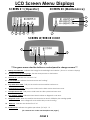
LCD Screen Menu Displays
SCREEN # 1 (Operator)
SCREEN #3 (Maintenance)
5
6
7
1
11
4
2
10
3
1
SCREEN W/ERROR CODE
1
8
11
2
9
***Use green menu selection button on control panel to change screens***
1.
Battery level indicator - Indicates the energy level remaining in the batteries. (Shown on all menu displays)
2.
Scrubdeck down pressure gauge - Sets the down pressure on the brushes.
3.
Vacuum on - Indicates the vacuum is "on".
4.
Scrub motors on - Indicates the brush motors are "running".
5.
Key switch hour meter - Tells you the total hours the machine has been on.
6.
Scrub brush hour meter - Tells you the total hours the brush motors have been used.
7.
Transport hour meter - Tells you the total hours the drive system has been used.
8.
Error warning symbol - Indicates when there has been a diagnostic code error.
9.
Diagnostic code - When the machine has detected an error it will display the warning symbol
10.
Water on - Indicates the solution flow is "on"
and a diagnostic code which tells you what's wrong.
11. Solution level - Indicates the gallons per minute (G.P.M) 0 - 1.0 .
(For common error codes and descriptions see pages .)
PAGE 9
Machine Setup
Uncrating Machine and
Connecting Batteries
1. Carefully check the crate for any signs of
damage. Batteries are in the unit.
2. To uncrate the machine, remove banding
from around the crate. Take off the top and
sides and dispose of properly.
3. Remove banding from machine. Remove
the chocks around the drive wheels.
4. Turn all switches to the off position and
remove key.
5. Tip back seat to expose the battery
compartment and check to see that the
battery cables are connected.
A standard machine is equipped with (6) 6-volt,
deep cycle, 325 ah batteries, which form a 36
volt system. Maximum battery dimensions are
7-1/8"W x 12-1/4"L x 13-1/4"H.
6. Verify that all of the battery cables are
connected to the batteries tightly. Locate any
loose ones and connect to the open terminal.
Tighten with 9/16" wrench. (DO NOT OVER
TIGHTEN!) Batteries are heavy but easily
damaged. Put covers in place. (See picture to
the left)
7. Turn on main power switch and check the
battery condition meter to ensure correct
installation.
8. Fold down ramp, and drive machine off of
the base.
Notify the carrier immediately if concealed
damage is discovered.
PAGE 10
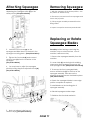
Removing Squeegee
Attaching Squeegee
1. Lower the squeegee mounting plate by
depressing the squeegee switch (A) to the
down position. (See picture below)
1. With the squeegee in the down position, turn
key switch off & remove key.
2. Disconnect vacuum hose from squeegee and
loosen the (4) knobs.
3. Pull squeegee assembly rearward from the
lifting carrier.
4. Inspect or repair as necessary and reinstall.
Replacing or Rotate
Squeegee Blades
A
2. Loosen the four knobs (B) on the
squeegee and slide them into the slots in the
squeegee mounting plate. (See picture below)
For safety: before leaving or servicing the
machine, stop on a level surface, turn off
machine, and remove key.
3. Tighten the four knobs (B) and connect
vacuum hose (C) from the machine to the
squeegee.
(See picture below)
1. Remove the squeegee assembly from the
machine.
2. Loosen latch (E) and swing both retaining
straps away from squeegee to remove the
rear squeegee blade. (See picture at lower left)
4. You may have to adjust the squeegee
pitch by turning the pitch adjustment knob (D).
(See picture below)
3. To remove the front squeegee blade,
remove all the knobs (F) on the front of the
squeegee assembly, then remove the
retaining strap that secures the blade in place.
(See picture below)
4. Rotate the squeegee blades to new edge
position or replace as required.
5. Install blades on the locating pins of
squeegee assembly.
6. Reinstall squeegee retainer straps.
7. Retighten front knobs & rear latch.
D
C
B E
F
5. Note vac exhaust, dual vac out
*assists in drying (See picture above)
PAGE 11
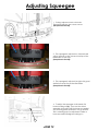
Adjusting Squeegee
1. Turning adjustment knob clock-wise
(Tightening) will raise tips & lower center.
(See picture to the left)
1
2. This squeegee is adjusted too far back and
will not pick up on the corners. Note tips of the
blades are off the floor.
(See picture to the left)
3. This squeegee is adjusted just right with good
deflection across the entire rear blade.
(See picture to the left)
4. To adjust the squeegee trail wheels, first
loosen locking nut (A). Then turn the wheel
assembly clock-wise until it bottoms out against
the mounting plate and back it off (3) full turns.
This is a starting point for adjustment. Raise or
lower as needed. Retighten locking nut.
A
PAGE 12
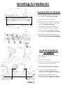
Leveling Scrubdecks
Leveling Disk Scrubdeck
1. Drive machine to a flat level surface and
turn machine off. (See picture to the left)
2. Deck should be raised off the floor.
Measure from
deck to floor
Measure from
deck to floor
3. With the shrouds off, measure from the ground
to a parallel surface on all four corners of the
scrubdeck. (See picture to the left)
3. If the measurements are not the same the
deck is not level and needs to be adjusted.
4. Loosen the (2) locking nuts (4) and adjust
the hexagonal arm (5). (See picture to the left)
5. Extending the adjustable arms raises the
front and lowers the rear of the scrubdeck.
Measure & Retighten. (See picture to the left)
4
5
4
4
5
Leveling Cylindrical
Scrubdeck
1. Drive machine to a flat level surface and
turn machine off.
2. Raise the deck off the floor.
3. Measure from the ground to a parallel edge
on all four corners of the scrubdeck.
4. If the measurements are not the same the
deck is not level and needs to be adjusted.
5. Loosen the locking nut (4) and turn the
hexagonal arm (5) on each side of the
scrubdeck to level it. (See picture to the left)
Measure from
deck to floor
Measure from
deck to floor
PAGE 13
6. Extending the adjustable arm raises the
front and lowers the rear of the scrubdeck.
Measure & Retighten. (See picture to the left)
Attaching Disk Brushes/Pads
1.
Turn "on" machine power.
2.
Raise the scrub deck by depressing the
brush switch (A) to the ("0") position and turn
machine power "off". Disconnect batteries.
(See picture to the left)
3.
Loosen knobs (B) and remove shrouds to access
scrub deck (See picture to the left)
4.
Attach pads to pad drivers before connecting
pad drivers to motor hub. (See picture to the left)
5.
Attach brushes or pads to motor hubs.
squeeze the scissor locking device (C) and lift
brush up on to the motor drive hub. Make
sure the scissors close and lock once the
brushes are on. (See picture to the left)
6.
When brushes are attached put shrouds
back on machine and tighten knobs.
A
B
B
C
***FOR CORRECT PAD APPLICATION , CALL YOUR LOCAL DEALER***
PAGE 14
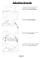
Adjusting Shrouds
1.
The shroud must be adjusted correctly in order
to have proper water control during turns.
the front of the shroud should be slightly
higher than the rear. (See picture to the left)
2. To adjust shrouds loosen knobs (A) and
remove shroud. (See picture to the left)
A
3.
B
Spin the RED shroud support (B) up or down to get
adjustments. (See picture to the left)
B
4. Once adjusted to the proper height put the shrouds
back on top of adjustment supports and tighten
knobs back down. (See picture to the left)
PAGE 15
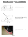
Adjusting Cylindrical Side Wipers
1. The cylindrical deck comes euipped with side wipers
for increased water control when turning.
(See picture to the left)
C
2. To adjust the side wipers, first loosen the locking nut
(A), then turn the adjusting screw (B) in to raise or out to
lower the height of the side wiper blade. The spring (C)
provides tension during adjustment.
(See picture to the left)
A
B
4. A properly adjusted side wiper will have slight blade
deflection on the floor when turning.
(See picture to the left )
PAGE 16
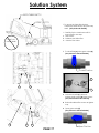
Solution System
BOTH TANKS EMPTY !
STRAP
1. To access the items listed below,
completely drain solution and recovery
tanks (See picture to the left)
I. Carefully tip the tank back until it is
supported by the strap.
II. Gate Valve
III. Stainless steel inline filter
IV. Solution Flow Valve
DONT LAY
UNDER TANK!
2. To clean filter (A) close gate valve (B).
(See pictures to the left & below)
Closed Position
C
A
B
D
3. Unscrew clear lid (C), remove
stainless steel screen (D), rinse screen.
(See pictures above & to the left)
4. Reinstall stainless filter screen & tighten
cap.
5. Open gate valve (E)
(See pictures to the left & below)
E
D
C
PAGE 17
Open Position
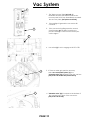
Vac System
A
B
1.
The "high recovery" light (A) (red) will
illuminate and the horn will sound when the
recovery tank is full. Stop immediately and drain
the recovery tank. (See picture to the left)
2.
If the red light is ignored the vac motor will
overheat.
3.
If the vac motor is pulling excessive current,
circuit breaker (B) (50 amps) may blow to
prevent damage. If this occurs contact your
service agent.
C
4. Vac switch (C) is set to engage at 45-50" of lift.
C
D
5. If foam or water gets past the recovery
tank "vac screen/ball system" (C) the
"unloader valve" (D) will drain it from the vac box.
(See picture to the left and picture below)
6. "Unloader valve" (D) is located on the bottom of
the vacuum box in front of the vac motor.
(See picture to the left)
PAGE 18
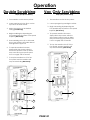
Operation
Pre-cleaning check list One pass scrubbing
Steps: (see picture below)
Read and understand the safety section on
page 5 and 6 before operating machine.
1. Turn machine on with the key switch.
1. Check battery condition gauge on
the Central Command II LCD screen.
Make sure batteries are fully charged
before using.
2. Lower squeegee by pressing the switch.
2.
Check the condition of pads or brushes.
4. Adjust the solution +/- to the desired
setting. (start at half way).
3.
Check the condition of the squeegee blades.
4.
Transport the machine to the filling
station. Raise the scrub head and
squeegee when transporting.
5.
Turn machine off.
6.
Open solution fill door on the top of
the tank and fill the tank up with
clean water or "approved" detergent. For help call
Powercat Solutions at 414-745-9337. Foam in the
recovery tank is usually an indication of excessive soap.
(See picture below.)
7.
Add cleaning chemical. Use the proper
dilution ratio indicated on the bottle.
3. Lower scrub head to the floor, use the
top half of the brush switch.
5. Begin scrubbing by depressing the
foot pedal slowly and then to the speed
required. (Not shown)
6. Start scrubbing at the #1 or # 2 marks,
do not use the #4 or #5 marks without
management's approval.
7. To operate machine in reverse,
simply switch the reverse switch to
the reverse position, back up alarm
may sound and your reverse speed
is set to roughly 70% of forward.
8. To stop the machine, let off of the
foot pedal and the machine will
stop automatically. (Not shown)
Note: Use only nonflammable commercial
9. Depressing the "uni-touch" button activates
the solution, vacuum, and brushes
simultaneously.
cleaning chemicals.
1
Solution Fill Port
6
2
Solution Fill
"Sight Tube"
4
9
PAGE 19
3
7
Operation
Double Scrubbing
Steps: (see picture below)
Vac Only Scrubbing
Steps: (see picture below)
1. Turn machine on with the key switch.
1. Turn machine on with the key switch.
2. Lower scrub head to the floor, use the
top half of the brush switch.
2. Lower squeegee by pressing the switch.
3. Begin vacuuming by depressing the
foot pedal slowly and then to the speed
required. (Not shown)
3. Adjust the solution to the desired
setting. (set half way)
4. Begin scrubbing by depressing the
foot pedal slowly and then to the speed
required. (Not shown)
5. Start scrubbing at the #1 or # 2 marks,
do not use the #4 or #5 marks without
management's approval.
4. To operate machine in reverse,
simply switch the reverse switch to
the reverse position, back up alarm
may sound and your reverse speed
is set to roughly 70% of forward.
5. To stop the machine, let off of the
foot pedal, and the machine will
stop automatically. (Not shown)
6. To operate machine in reverse,
simply switch the reverse switch to
the reverse position, back up alarm
may sound and your reverse speed
is set to roughly 70% of forward.
1
7. To stop the machine, let off of the
foot pedal, and the machine will
stop automatically. (Not shown)
1
5
2
4
2
3
6
PAGE 20
Operating Hints
C
B
A
1. Observe the amount of solution the machine is
dispensing on the floor and adjust to the desired flow.
To increase the solution flow rate, push solution switch
(A) +, to decrease push solution switch (A) -.
(See picture to the left)
2. Keep an eye on the "red" recovery full light (B) to
make sure there is not foamy buildup in the recovery
tank. If excess foam begins to develop, pour a
recommended foam control solution into the
recovery tank.
(See picture to the left)
3. Always operate at lower speeds when scrubbing
around walls and objects. You should reduce the
speed, to maintain control when turning.
4. If squeegee starts to streak, raise and wipe the
blades with a clean cloth. If the problem continues,
check the blades for wear or damage, and rotate if
needed.
5. Change or turn over pads when dirty. Rotate the
scrub brushes every week.
6. Stay clear of objects protruding from the floor,
such as sockets, grates, for they will damage the
pads and squeegee blades.
Sight Tube
7. During brief stops you should turn everything off,
the brushes and solution will automatically stop when
the foot pedal is released.
8. Always keep an eye on your gauges. They let you
know the status of a particular system at a glance. If
your battery gauge is reading low, you must stop
immediately, and recharge. Running the batteries
dead, will result in damage to the batteries.
9. When you run out of solution, raise the brushes,
and continue to vacuum the remaining water until it
is consumed. The "yellow" low solution light (C) will
light up when the solution is low and the sight tube
on the back of the tank tells you how much solution
is left in the tank, (See picture to the left)
10. When you are ready to stop, pick up the brushes,
turn off the solution switch, pick up the squeegee,
and drive the machine back to the charging area.
PAGE 21
Drain Recovery Tank
Drain Solution Tank
Always empty recovery tank when refilling the solution
tank. To drain the recovery tank, perform the following
steps.
To drain left over cleaning solution from the solution tank,
perform the following steps.
1. Pull the clear sight tube/drain hose (A) off barbed fitting.
(See picture below)
1. Remove drain hose "B" and unscrew cap. Open the
top "recovery access lid" and flush out with fresh water
to keep tank clean. (See picture below)
2. Rinse out tank and solution flow system with clean water.
A
B
Overide Parking Brake
The parking brake must be released "prior" to attempting to
"push/pull" the machine manually. Perform the following
steps in any order.
2. Remove cap and begin draining, squeeze "C"
to control flow. (See picture below)
C
1. Disconnect both positive and negative leads (1 & 2) from
the traction motor. (See picture below)
* It is the customers responsibility to verify that discarded
water is in compliance with local, state, and federal
laws. DO NOT DRAIN INTO "STORM DRAINS" !
1
3. Open the top "recovery tank lid" and flush out with
fresh water to keep tank clean. Rinse the recovery tank
after every use. This will prevent heavy build up on the
bottom of the tank, foul odors and clogging of the drain
hose. Empty "Drain Saver".
2
2. Turn wingnut (3) clockwise to release the parking brake.
(See picture below)
3
4. Once tank is empty, put the cap back on and place
hose back on hook.
PAGE 22
Recovery Tank
Drain Saver
Recovery Tank
Float Shut-Off
When water is no longer being vacuumed
from the floor and the vacuum fan is
operating, the ball float has engaged the red
high recovery light (1) will come on.
(See picture below)
The vacuum motor will not vacuum water with
recovery tank full. The recovery tank must be
drained
1
1. The float shut-off (2) screen can be
cleaned in or out of the machine.
The recovery tank drain saver will help prevent the drain
from becoming clogged with debris.
1. The drain saver screen should be emptied and cleaned
after you drain the tank.
2. To clean, pull hose (4) out of drain saver and remove
screen. Empty screen into trash, wipe material off screen
and then rinse.
4
3. When finished place screen back into the recovery tank
and re-insert hose into screen (5).
2. To clean the float shut-off while it is inside
the machine wipe material off screen
then rinse. Check that the ball is also
clean and moves freely.
3. To remove the float shut-off, remove the
white clamp (3) grasp the screen with one
hand and pull down to remove.
4. Screens, gaskets, and shutoff balls must be
in place.
5
4. The screen saver must always be in place when the
machine is in use to prevent clogging of drain.
3
2
PAGE 23
Standard Battery Charging
Charger Specifications
Output voltage of 36 volts. (Standard)
Output current of 36 amps max. (Standard)
Input voltage of 110 volts/60 Hz. (standard)
Automatic shut off circuit.
Made for deep cycle batteries.
Standard Charger
Caution: the following instructions are intended for the
36v charger supplied with the machine. Do not use
any non OEM charger with this machine.
Danger: always charge batteries in a well ventilated area.
Batteries emit hydrogen gas. Explosion or fire can result.
Keep sparks and flame away. Shield eyes when servicing
batteries and avoid contact with battery acid.
Leave access panel open when charging!
1. Transport machine to a well ventilated area for
charging.
2. Turn the machine off.
3. Hinge opens the tank to expose the batteries.
(See picture to the left)
Caution: (always wear eye protection when batteries
are exposed)
4. Check the water level in each battery. Do not
charge the machine unless the water is slightly higher
than the plates. If needed, add enough distilled
water to 1/2” above the plates. Do not over fill.
Batteries can overflow during charging. Replace
caps before charging.
5. With the grey (175) charger plug disconnected
from the machine, plug the charger power cord into
a grounded 110 volt standard wall outlet.
6. Connect the grey charger plug into the battery
charging port (A) located on the seat pedestal.
7. The charger will automatically begin charging,
and automatically shut off when fully charged
(Check gauge)
8. After the charger has turned off, unplug the grey
charger plug from the machine and disconnect the
charger from the wall outlet.
A
9. Recheck the cell level after charging. If needed,
add distilled water up to the correct level. Be certain
to replace the caps securely and to wipe off the top
of the batteries.
PAGE 24
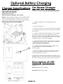
Optional Battery Charging
Charger Specifications On-Board Charger
Caution: the following instructions are intended for the 36v
"optional" on-board charger (A). (See left middle picture)
Output voltage of 36 volts. (optional)
Output current of 30 amps max.
Input voltage of 110 volts/60 Hz.
Automatic shut off circuit.
Made for deep cycle batteries, wet or sealed.
Danger: always charge batteries in a well ventilated area.
Batteries emit hydrogen gas. Explosion or fire can result.
Keep sparks and flame away. Shield eyes when servicing
batteries and avoid contact with battery acid.
Leave access panel open when charging!
1. Transport machine to a well ventilated area for
charging.
2. Turn the machine off.
3. Hinge open the tank to expose the batteries. (See figure
50.) Caution: (always wear eye protection when batteries
are exposed)
4. Check the water level in each battery. Do not charge
the machine unless the water is slightly higher than the
plates. If needed, add enough distilled water to 1/2” above
the plates. Do not over fill. Batteries can overflow during
charging. Replace caps before charging.
5. Plug the extension cord into a grounded 110 volt/60 Hz
standard wall outlet & flip switch. (See picture to the left)
* NOTE: MUST HAVE 20 AMP SERVICE.
A
6. The charger will automatically begin charging, and
automatically shut off when fully charged
(Check gauge)
7. After the charger has turned off, unplug the extension
cord from the machine and disconnect from the wall
outlet. (See picture to the left)
8. Recheck the cell level after charging. If needed, add
distilled water up to the correct level. Be certain to replace
the caps securely and to wipe off the top of the batteries.
Description of LED
Red LED Battery level low.
Yellow Led Battery at 1/2 charge.
Green LED battery fully charged.
Close-up of charger LCD
PAGE 25
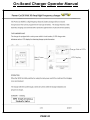
On-Board Charger Operator Manual
Charge Status LED's
Main Power
Switch
PAGE 26
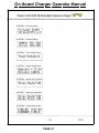
LCD Display
On-Board Charger Operator Manual
PAGE 27
On-Board Charger Operator Manual
PAGE 28
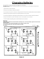
Changing Batteries
Stop machine in a clean area next to the charger. Turn off machine.
For safety: Before leaving or servicing the machine; stop on level surface, turn off machine and remove key.
Use eye protection.
1. Tip back tank to expose batteries.
2. Disconnect main battery cables from machine.
3. Use the proper size wrench to disconnect main ground wire first and secure cable terminal away from batteries.
4. Disconnect main positive lead and secure cable and remove one at a time.
5. Loosen both terminals on each jumper cable and remove one at a time, and place away from machine.
6. Prepare a suitable site to place the batteries, store on a wood pallet, not on concrete.
7. Attach suitable battery lifting device and lift batteries from the machine
Warning!
Batteries are a possible environmental hazard & extremely heavy. Consult your battery supplier for safe removal &
disposal methods.
Note orientation of the positive and negative posts is critical for cables to reach.
Do not lift from battery posts, which cannot support the weight.
(See below)
36 VOLTS !
>
-
-
+
+
-
-
PAGE 29
+
+
+
Front of machine
-
+
@
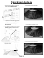
Side Broom System
1. Flip side broom switch (A) up to lower and
engage broom. (See picture below)
6. Picture below shows brooms to high.
A
2. To adjust side broom height, loosen locking
nut located behind screwhead (B) of screw
that is in front of scrubdeck just inside the side
wall of frame on each side of the machine.
Use 1/2" wrench to loosen locking nut.
(See picture below)
7. Picture below shows brooms to low.
3. Turn adjustment screw (B) counter-clockwise
(loosens) to lower side brooms. Turn screw
clock-wise (tightens) to raise side brooms.
4. Retighten locking nut.
B
8. Picture below shows brooms just right.
5. Side broom adjustment slot (C).
(See picture below)
C
PAGE 30
Machine options
Overhead Guard
HD Side Doors
1. Your machine may be equipped with an"optional"
"Overhead Guard" (A) that helps protect the operator
from falling objects that are above the operators head.
(See picture below)
1. Your machine may be equipped with "optional"
"Heavy Duty Side Doors" (C) that helps protect the
machine's scrubdeck from collision damage.
(See picture below)
D
A
C
Non-marking tires
1. Your machine may be equipped with non marking
(D) tires, which may have reduced traction on some
floors (See picture above)
Industrial Battery
1. Your machine may be equipped with "optional"
"Heavy Duty Industrial Battery" and charger that
provides longer machine run time.
(See picture below)
Pre-treat Soap
1. Your machine is may be with "optional" "Pre-treat
Soap" (B).
2. It helps remove stains that a normal detergent can
not get out of floor. (See picture below)
B
E
PAGE 31
On-board charger
1. Your machine may be equipped with "optional"
"On-board charger (E) that will charge your machine.
(See picture to the left)
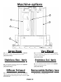
Machine options
D
A
E
B
C
Vac Wand
Spray Hose
(D) Your machine may be equipped with "optional"
(A) Your machine may be equipped with "optional"
Vacuum wand which allows you to vacuum up water
in hard to reach places.
(See picture below)
Spray hose. Permits cleaning in remote areas.
(See picture above)
Stainless Sol. tank
Stainless Rec. tank
(E) Your machine may be equipped with "optional"
(B) Your machine may be equipped with "optional"
Stainless steel Solution tank.
(See picture above)
stainless steel recovery tank.
(See picture above)
Removable Battery box
Diffuser Exhaust
(C) Your machine may be equipped with "optional"
diffuser exhaust which helps reduce noise and assist in
drying the floor by dispersing air evenly to the floor. (See
picture above)
PAGE 32
(F) Not shown. Coming in 2008
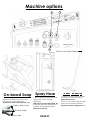
Machine options
C
B
A
On-board Soap
1. Switch toggel switch up once for
normal soap distribution and up twice
for heavy duty soap distribution.
(See picture at top of the page item "A").
Heavy duty soap
Normal soap
No soap
Attach vac hose here
Spray Hose
1. Turn on spray jet pump using the
togle switch on the central
command.
(See picture at top of page item "B" )
2. Detach srap hose from back of
machine and squieeze handel.
(See picture above)
PAGE 33
Vac Wand
1. Detach vac hose from squeegee
and attach it to the vac wand.
(See picture above)
2. Turn on vac motors using the togle
switch on the central command.
(See picture at top of page item "C" )
Maintenance
Daily Maintenance
Yearly Maintenance
1. Remove and clean pads or brushes. Never use soiled
pads when cleaning. Replace pads when they become
packed with residue.
1.
2. Remove and clean debris from the float shut-off screen
and drain saver located inside the recovery tank.
Storing Machine
3.
Drain and rinse tanks thoroughly.
4. Inspect vacuum hose for any objects obstructing the
air flow.
5. Raise squeegee and wiper blades with a clean cloth.
Store squeegee in the raised position to prevent damage
or setting of the blades.
6. Wipe down machine if needed. Use a nonabrasive,
non solvent cleaner, or a clean damp cloth.
7.
Recharge the batteries if needed.
Weekly Maintenance
1. Check battery water level in each cell of the batteries,
and fill as needed. Always usedistilled water to refill
batteries. Batteries should be filled approximately 3/4" to 1"
above the plates. Overfilling will cause the batteries to
leak during charging. The charging process creates gas
bubbles inside the battery, which effectively increases the
volume of the electrolyte.
2.
1. Be sure to flush the tanks out completely. To thoroughly
flush out any solution chemicals in solution line and
valves, refill solution tank with a few gallons of warm clean
water and run machine until tank is empty.
2.
Open the recovery tank lid to promote air circulation.
3.
Raise brushes and squeegee.
Checking Battery Specific Gravity
Use a hydrometer to check the battery specific gravity.
Checking Gravity
A. Hydrometer
B. Battery
Note: do not take readings immediately after adding
distilled water, if water and acid are not thoroughly mixed,
the reading may not be accurate.
Check the hydrometer against this chart
Clean battery tops to prevent corrosion.
3. Rotate brushes. Rotate the left to the right and right to
left. On cylindrical models from front to back, or end to
end if using different materials.
4. Drain and rinse tanks thoroughly. To thoroughly flush
out any solution chemicals in solution line and valves,
refill solution tank with a few gallons of warm clean water
and run machine until tank is empty.
Monthly Maintenance
1. Check scrub head and squeegee lifting cables for
wear and spring tension.
2. Check machine for water leaks and loose nuts and
bolts.
3. Check to see if battery cables are tightened
(Tighten if needed)
4.
Call your local dealer for yearly maintenance
Check parking brake
PAGE 34
SPECIFIC GRAVITY
BATTERY CONDITION
@ 80v F (27vC)
1.265
1.225
1.190
1.155
1.120
100% CHARGED
75% CHARGED
50% CHARGED
25% CHARGED
DISCHARGED
Note: if the readings are taken when the
battery electrolyte is any temperature
other than 80vF (27vC), the reading
must be temperature corrected.
To find the corrected specific gravity reading
when the temperature of the battery electrolyte
is other than 80vF (27vC): add (+) to the specific
gravity reading 0.004 (4 points), for each 10vF
(6vC) above 80v (27vC).
subtract (-) from the specific reading 0.004
(4 points), for each 10vF (6vC) below 80vF (27vC).
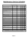
Maintenance Service Schedule
Maintenance Sevice Schedule
Before each work After each work
50 hrs 100 hrs 200 hrs
period
period
Check water level of batteries after charging
X
add distilled water if necessary
Check that recovery tank cover seals tightly
X
Visualy check for damaged or worn tires
X
Check brushes or pads for proper installation
X
Check vacuum hose connections
X
Check that squeegee is securely attached
X
and properly adjusted
Check that side squeegees are properly
x
adjusted
Check for attached drain hose, plug and
X
caps
Check parking brake and steering for proper
X
operation
Inspect vacuum filter for debris
X
Clean out solution tank and filter, check flow
X
Run vacuum motors to dry
X
Clean brushes or pads and check for wear
X
Clean main and side squeegee blades and
X
check for wear
Clean out recovery tank and vacuum filter
X
Clean and inspect flow shutoff
X
Clean outside of tanks and check for
X
damages
Store with tank covers open
X
Charge batteries
X
Check side squeegee for wear
X
Clean off top of batteries
X
Check battery cells with hydrometer
X
Inspect scrub deck skirt
X
Clean solution strainer
X
Check battery connections are tight
X
Check parking brake adjustment
X
Check battery case and battery
X
compartment
Check brake for damage or wear
X
Clean pivot points on squeegee and scrub
X
deck
Check all motors for carbon brush wear
X
Check motor commutators
X
Check steering chain tensioner
X
NOTE: Traction drive, wheels and batteries should be serviced based on traction drive
hour meter. The scrub brush hour meter should be used for all other service schedule items.
Maintenance
PAGE 35
Preventative Maintenance Records
CUSTOMER INFORMATION
CUSTOMER
ADDRESS
CITY
STATE
ZIP CODE
MACHINE INFORMATION
MODEL #
WORK ORDER#
BATTERY CONDITION
SERIAL #
HOUR METER:
Cell #1
Cell #2
Cell #3
Battery # 1 Hydrometer Reading
Battery # 1 Water Condition
Battery # 2 Hydrometer Reading
Battery # 2 Water condition
Battery # 3 Hydrometer Reading
Battery # 3 Water Condition
Battery # 4 Hydrometer Reading
Battery # 4 Water condition
Battery # 5 Hydrometer Reading
Battery # 5 Water Condition
Battery # 6 Hydrometer Reading
Battery # 6 Water Condition
Clean Battery Tops. Check Battery Cable and Terminal Condition
NOTES:
BRUSH CONDITION
Scrub Brush Fiber Length
Rotated Brushes
Brush Drive Sockets
Good
Worn
Drive Hubs
Good
Worn
Needs Replacement
Side Broom Condition
Good
Worn
Needs Replacement
CHECK OPERATION AND CONDITION OF:
IN SPEC
REPAIR
PROBLEM
Steering wheel Tilt Mechanism
Key Switch
Horn
Head Light
LCD Display
Page Button
Brush Pressure Button
Brush Pressure Managers Lock Out
Foot Pedal
Reverse Switch
Back Up Alarm
One Touch Switch
PAGE 36
Needs Replacement
Rotated Side to Side
Preventative Maintenance Records
CHECK OPERATION AND CONDITION OF:
IN SPEC
REPAIR
PROBLEM
IN SPEC
REPAIR
PROBLEM
IN SPEC
REPAIR
PROBLEM
Brush Switch
Solution Potentiometer
Solution Solenoid
Solution Drain Valve
Low Solution Light
Brush Deck Lift System
Brush Motors & Motor Brushes
Vacuum Switch
Vacuum Motor performance
Off-Board Vac Switch
Squeegee Lift System
Squeegee Adjustment
Squeegee Blades
High Recovery Light
High Recovery Alarm
Drain Hose and Plug
Side Broom Operation
Spray Jet Switch
Spray Jet Pump, Hose & Nozzle
Strobe Light
Battery Charger Connectors
Battery Charger
CLEAN AND/OR LUBRICATE
Solution Filter
Squeegee pivot points & Knobs
Scrub Deck Linkage
Steering Chain
VISUALLY INSPECT:
Solution Tank Condition
Recovery Tank & Lid Condition
Drain Saver
Vacuum floats
Vacuum Filter
Vacuum Motor Brushes
Vacuum Hoses
Solution Hoses
Blade retainers & hardware
Squeegee Wheels
Brush skirts
Brush Motor Brushes
Brush or Pad Driver Condition
Drive Wheel Condition
Rear Wheels Condition
All Rollers
COMMENTS
Technician's Name
Technician's Signature
Date
Customer's Name:
Customer's Signature
Date
PAGE 37
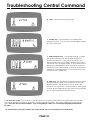
Troubleshooting Central Command
Note: this machine is operated by a sophisticated electronic "controller" that has many fail-safes within it. It
self-analyzes problems and flashes a four-digit alpha-numeric code of what is wrong in the LCD window.
Most of these codes require a technician attention. You should not attempt repairs you are unfamiliar with, especially if
you are not authorized to work on this equipment.
The complete list of codes is published in the simplified electronic troubleshooting manual, which is available to
authorized and certified distribution technicians. However, we have included the basic codes that you can usually
resolve yourself.
7601 and 7602 Error. Scrub deck current over load.
This can occur when driving over a bump in the floor. To
restart, turn off the key and turn it on again. To avoid this
error, either slow down on bumpy parts of the floor, or
reduce down pressure on the pads.
1.
2. 1500 Error. There is an open in the parking brake
circuit. Check the parking brake wiring and the parking
brake coil to find the open circuit.
3. 7700, 7701, 7702, and 7703 Error. The vacuum motor
has exceeded their authorized power limits. Turn off key
and turn on again to clear.
4. BOOST ON Allows front wheel drive to draw more
power when needed to climb ramps for 30 seconds.
PAGE 38
Troubleshooting Central Command
5. 7700. Vacuum motor circuit is open.
6. Throttle error. You pressed the foot pedal before
turning on the key. Turn off the key and try again, leaving
foot off of the pedal.
7. 2C00 and 2C01 error. Low voltage warning. Voltage
has dropped down below the minimum required to
operate the machine. If you wait a few minutes, the
batteries may come up in voltage, allowing you to drive
very slowly to the recharge station. If not, you will have to
release the parking brake (on the front wheel, pull lever
toward the front of the machine to release) and push the
machine to recharging station. You must disconnect the
traction motor! (+ cable first)
8. 7802 error. The traction motor pulled excessive current
perhaps running a ramp for more than the 60 seconds
allowing for this. Turn off the key, turn on again, and
continue. You should not use this machine to climb ramps
so steep and so long that this code comes up repeatedly,
or you could overheat the traction motor.
9. All other error codes. Turn off the key, and disconnect the positive battery cable from the batteries for more than
one minute (the time is needed to drain the controler on-board capacitor). Reconnect cables, being sure that it is
tight. Too loose and you will burn battery. If you over tighten the cables you can damage the battery lead terminal.
Try again.
10. If the problems cannot be solved by any of this solution, call your local dealer service department.
PAGE 39
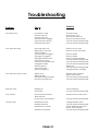
Troubleshooting
Problem
Cause
Solution
No power, nothing operates
Faulty key switch
Batteries need charging
Faulty battery
Loose battery cable
Main circuit breaker tripped
Contact local servicing dealer
See charging batteries
Replace battery
Tighten loose cable
Wait 5 minutes for auto reset
Determine cause and correct
Brush motor(s) do not operate
Brush deck is not down
Foot pedal is not depressed
Brush circuit breaker tripped
Carbon brushes worn
Faulty brush motor or wires
Put brush deck down
Engage foot pedal
Wait 5 minutes for auto reset
Determine cause and correct
Contact local servicing dealer
Contact local servicing dealer
Drive motor does not operate
Recharge switch misadjusted
Faulty speed controller or wires
Faulty drive motor
Faulty wiring
Carbon brushes worn
Contact local servicing dealer
Contact local servicing dealer
Contact local servicing dealer
Contact local servicing dealer
Contact local servicing dealer
Vacuum motor does not operate
Squeegee is in the up position
Faulty vacuum switch
Vacuum circuit breaker tripped
Faulty vacuum motor
Rotate squeegee lift lever down
Try operating "white” toggle
Wait 5 minutes for auto reset
Determine cause and correct
Contact local servicing dealer
Drive motor runs incorrectly
Faulty speed controller or wires
Faulty potentiometer
Loose wires
Contact local servicing dealer
Contact local servicing dealer
Contact local servicing dealer
Insufficient solution flow
Solution tank low
Refill solution tank, drain recovery
tank
Move lever to on
Remove cover and clean
Remove and blow out with
compressed air
Remove cover and clean
Flow knob turned down
Solution filter clogged
Solution line clogged
Solution valve clogged
PAGE 40
Troubleshooting
Problem
Cause
Solution
No solution flow
No solution in tank
Solution valve off
Solution switch off
Solution screen clogged
Faulty solution solenoid
Faulty solution switch
Fill solution tank
Rotate lever to on
Turn solution switch on
Remove and clean screen
Contact local servicing dealer
Contact local servicing dealer
Poor water recovery
Recovery tank is full
Ball/screen in recovery
Tank is clogged
Vacuum hose is clogged
Squeegee is clogged
Squeegee blade is worn
Faulty vacuum hose
Vacuum motor gasket torn
Tank gasket faulty
Drain plug loose
Vac motor faulty
Battery charge low
Empty recovery tank
Remove screen and clean
Poor water recovery on turns
Wipers worn
Wipers chatter
Squeegee swing is binding
Incorrect squeegee size
Replace wiper material
Tighten pivot points
Contact local servicing dealer
Contact local servicing dealer
Rear tires noisy
Bearing dry
Faulty hubs
Grease bearings
Contact local servicing dealer
Poor traction
Excessive brush pressure
Worn drive tire
Heavy soap concentration
Reduce pressure with switch
Batteries run down
Batteries still down
Batteries low on water
Charge batteries twice
Contact local servicing dealer
Fill with distilled water to 3/4"
above the lead plates
Contact local servicing dealer
Short run time
Batteries over cycled
PAGE 41
Remove debris
Remove debris
Rotate or replace blades
Contact local servicing dealer
Contact local servicing dealer
Contact local servicing dealer
Tighten lid
Contact local servicing dealer
Charge batteries overnight
Contact local servicing dealer