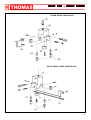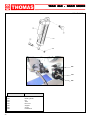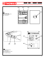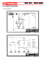
1
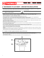
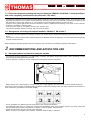
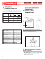
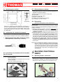
USE AND MAINTENANCE MANUAL
TRAD 260
THOMAS
MULTI - MODE
10/2003
THOMAS S.p.A. - Via Pasubio, 32 - 36033 Isola Vicentina (VI) - Telephone 0444 / 97.61.05 - Fax 0444 / 97.69.34
TRAD 260 - MUL
TI MODE
MULTI
Contents
Contents ........................................................................ "
2
Ordering spare parts .................................................... "
2
Guarantee ...................................................................... "
2
Machine certification and identification marking .... "
3
CHAPTER 1
Reference to accident-prevention regulations .......... "
1.1 - Advice for the operator ........................................... "
1.2 - Location of shields against accidental contact with
the tool .................................................................... "
1.3 - Electrical equipment according to European
Standard "CENELEC EN 60 204-1" ....................... "
1.4 - Emergencies according to European Standard
"CENELEC EN 60 204-1" ....................................... "
5
CHAPTER 2
Recommendations and advice for use ....................... "
2.1 - Recommendations and advice for using the machine . "
5
5
CHAPTER 3
Technical characteristics ............................................. "
3.1 - Table of cutting capacity and technical details ....... "
6
6
CHAPTER 4
Machine dimensions - Transport - Installation
Dismantling ................................................................... "
4.1 - Machine dimensions ............................................... "
4.2 - Transport and handling of the machine .................. "
4.3 - Minimum requirements for the premises
housing the machine .............................................. "
4.4 - Anchoring the machine ........................................... "
4.5 - Instructions for electrical connection ...................... "
4.6 - Instructions for assembly of the loose parts and
accessories ............................................................. "
4.7 - Disactivating the machine ....................................... "
4.8 - Dismantling ............................................................. "
4
4
4
5
6
6
6
6
7
7
7
7
7
CHAPTER 5
Machine functional parts ............................................. "
5.1 - Operating head or saw frame ................................. "
5.2 - Vice ......................................................................... "
5.3 - Bed .......................................................................... "
7
7
8
8
CHAPTER 6
Description of the operating cycle ............................. "
6.1 - Starting up and cutting cycle .................................. "
8
8
CHAPTER 7
Regulating the machine ............................................... "
9
7.1 - Blade tension assembly .......................................... "
7.2 - Blade guide blocks .................................................. "
7.3 - Vice .......................................................................... "
7.4 - Spring adjustment ................................................... "
7.5 - Cutting angle adjustment ........................................ "
7.6 - Saw frame lowering control device ......................... "
7.7 - Changing the blade ................................................. "
7.8 - Replacing saw frame return spring ........................ "
9
9
10
10
10
11
12
12
CHAPTER 8
Routine and special maintenance .............................. "
8.1 - Daily maintenance .................................................. "
8.2 - Weekly maintenance .............................................. "
8.3 - Monthly maintenance ............................................. "
8.4 - Six-monthly maintenance ....................................... "
8.5 - Maintenance of machine operating members ........ "
8.6 - Oils for lubricating coolant ...................................... "
8.7 - Oil disposal ............................................................. "
8.8 - Special maintenance .............................................. "
12
12
12
12
12
12
12
12
12
CHAPTER 9
Material classification and choice of tool .................. "
9.1 - Definition of materials ............................................. "
9.2 - Selecting blade ....................................................... "
9.3 - Teeth pitch .............................................................. "
9.4 - Cutting and advance speed .................................... "
9.5 - Blade running-in ...................................................... "
9.6 - Blade structure ....................................................... "
9.7 - Blade type ............................................................... "
Teeth shape and angle ........................................... "
Set ........................................................................... "
13
13
13
13
14
14
14
14
14
15
9.7.1 - Table of recommended cutting parameters .................. "
15
CHAPTER 10
Machine components ................................................... " 16
10.1- List of spare parts .................................................. " 16
CHAPTER 11
Wiring diagrams ........................................................... " 22
CHAPTER 12
Troubleshooting ............................................................ " 25
12.1- Blade and cutting diagnosis .................................... " 25
12.2- Electrical components diagnosis ............................ " 28
CHAPTER 13
Noise tests ..................................................................... " 28
Ordering spare part
- When ordering spare parts you must state:
MACHINE MODEL
SERIAL NUMBER
PART REFERENCE NUMBER
Without these references WE WILL NOT SUPPLY the spares. See point 10.1 - list of spare parts -
Guarantee
- The Company guarantees that the machine to which this manual refers has been designed and built to comply with safety regulations and that it has been tested for functionality in the factory.
- The machine is guaranteed for 12 months: the guarantee does not cover the electric motors, electric components, pneumatic
components or any damage due to dropping or to bad machine management, the failure to observe maintenance standards or bad
handling by the operator.
- The buyer has only the right to replacement of the faulty parts, while transport and packing costs are at his expense.
- The serial number on the machine is a primary reference for the guarantee, for after-sales assistance and for identifying the
machine for any necessity.
2
TRAD 260 - MUL
TI MODE
MULTI
Machine certification and identification marking
MACHINE LABEL
via Pasubio, 32
36033 ISOLA VIC. - ITALIA
MODEL
TYPE
TRAD 260
MULTI - MODE
SERIAL NUMBER
YEAR OF MANUFACTURE
(Space reserved for the NAME and STAMP of the DEALER and/or IMPORTER)
3
TRAD 260 - MUL
TI MODE
MULTI
1 REFERENCE TO ACCIDENT - PREVENTION REGULATIONS
This machine has been built to comply with the national and community accident-prevention regulations in force. Improper use
and/or tampering with the safety devices will relieve the manufacturer of all responsibility.
1.1 - Advice for the operator
- Check that the voltage indicated on the plate, normally fixed to the machine motor, is the same as the line voltage.
- Check the efficiency of your electric supply and earthing system; connect the power cable of the machine to the socket and the
earth lead (yellow-green in colour) to the earthing system.
- When the saw frame is in suspend mode (up) the toothed blade must not move.
- Only the blade section used for cutting must be kept unprotected. Remove guarding by operating on the adjustable head.
- It is forbidden to work on the machine without its shields (these are all blue or grey in colour).
- Always disconnect the machine from the power socket before blade change or carrying out any maintenance job, even in the case
of abnormal machine operation.
- It is forbidden to disconnect the "man present" device, known more correctly in the EEC as the " safety switch with hold-down action"
- Always wear suitable eye protection.
- Never put your hands or arms into the cutting area while the machine is operating.
- Do not shift the machine while it is cutting.
- Do not use any artful system or device (for ex. shim) to prevent the vice from locking the workpiece. Do not hold the workpiece with
your hand during the cutting process.
- Do not charge the workpiece from the right to the left-hand side with respect of the machine front.
- Do not wear loose clothing with sleeves that are too long, gloves that are too big, bracelets, chains or any other object that could get
caught in the machine during operation; tie back long hair.
- Keep the area free of equipment, tools or any other object.
- Perform only one operation at a time and never have several objects in your hands at the same time. Keep your hands as clean as
possible.
- All internal and/or internal operations, maintenance or repairs, must be performed in a well-lit area or where there is sufficient light
from extra sources so as to avoid the risk of even slight accidents.
1.2 - Location of shields against accidental contact with the tool
- Blue, grey right and left hand metal shields, fastened with screws onto the guide blade stationary head ( RIF. A ).
- Blue or grey metal shield fastened with screws onto the blade guide adjustable head, ensures covering of blade section not used in
cutting operation ( RIF. B ).
- Grey metal guard, fastened with knobs onto the saw frame, to protect from flywheels ( RIF. C ).
A
C
B
4
TRAD 260 - MUL
TI MODE
MULTI
1.3 - Electrical equipment according to Euro-pean Standard"CENELEC EN 60 204-1" which assimilates,
with some integrating modifications, the publication "IEC 204-1"
- The electrical equipment ensures protection against electric shock as a result of direct or indirect contact. The active parts of this
equipment are housed in a box to which access is limited by screws that can only be removed with a special tool; the parts are fed
with alternating current at low voltage (24 V). The equipment is protected against splashes of water and dust.
- Protection of the system against short circuits is ensured by means of rapid fuses and earthing; in the event of motor overload,
protection is provided by a thermal probe.
- In the event of a power cut, the specific start-up button must be reset.
- The machine has been tested in conformity with point 20 of EN 60204.
1.4 - Emergencies according to European Standard "CENELEC EN 60 204-1"
- In the event of incorrect operation or of danger conditions, the machine may be stopped immediately by pressing the red mushroom
button.
- The casual or voluntary removal of the protection shield of the flywheels causes the stepping-in of a microswitch that automatically
stops all machine functions.
NOTE: Resetting of machine operation after each emergency stop is achieved by reactivating the specific restart button.
2
RECOMMENDATIONS AND ADVICE FOR USE
2.1 - Recommendations and advice for using the machine
- The machine has been designed to cut metal building materials, with different shapes and profiles, used in workshops, turner’s
shops and general mechanical structural work.
- Only one operator is needed to use the machine, that must stand as shown in the picture.
- Before starting each cutting operation, ensure that the part is firmly gripped in the vice and that the end is suitably supported.
These figures show examples of suitable clamping of different section bars, bearing in mind the cutting capacities of the machine in
order to achieve a good efficiency and blade durability.
- Do not use blades of a different size from those stated in the machine specifications.
- If the blade gets stuck in the cut, release the running button immediately, switch off the machine, open the vice slowly, remove the
part and check that the blade or its teeth are not broken. If they are broken, change the tool.
- Check saw frame return spring to ensure proper balancing.
- Before carrying out any repairs on the machine, consult the dealer or apply to THOMAS.
5
TRAD 260 - MUL
TI MODE
MULTI
3.1 - Table of cutting capacity and technical details
CAPACITA` DI
TAGLIO
4
MACHINE DIMENSIONS
TRANSPORT
INSTALLATION
DISMANTLING
4.1 - Machine dimensions
0°
225
200
245 x 150
250 x 80
45° DX
140
140
140
60° DX
90
90
90 x 90
1800
3
TECHNICAL
CHARACTERISTICS
1750
4.2 - Transport and handling of the machine
Blade rotation three-phase electric
motor
2-speed
KW
1 ÷ 1.4
Coolant pump electric motor
KW
0.07
I
40 : 1
Flywheel diameter
mm
295
Blade dimensions
mm
2450x27x0.9
Blade cutting speed
m/1'
32 ÷ 64
Vice opening ( linear vice )
mm
270
°
40
Working table height
mm
940
750
Machine weight
Kg
300
Reduction gear in oil bath
Saw frame tilting
1000
If the machine has to be shifted in its own packing, use a forklift truck or sling it with straps as illustrated.
4.3 - Minimum requirements for the premises
housing the machine
- Mains voltage and frequency complying with the machine
motor characteristics.
- Environment temperature from -10 °C to +50 °C.
- Relative humidity not over 90%.
6
TRAD 260 - MUL
TI MODE
MULTI
4.4 - Anchoring the machine
760
1000
684
375
750
- If the sawing machine is to be out of use for a long period, it is
advisable to proceed as follows:
38
WALL
38
4.7 - Disactivating the machine
A
A
375
12
1) detach the plug from the electric supply panel
2) loosen blade
3) release the arch return spring
4) empty the coolant tank
5) carefully clean and grease the machine
6) if necessary, cover the machine.
SEZ. A - A
4.8 - Dismantling
MACHINE FRONT
STAND CONTOUR
- Position the machine on a firm cement floor, maintaining, at
the rear, a minimum distance of 1000 mm from the wall; anchor it to the ground as shown in the diagram, using screws
and expansion plugs or tie rods sunk in cement, ensuring that
it is sitting level.
4.5 - Instructions for electrical connection
- The machine is not provided with an electric plug, so the customer must fit a suitable one for his own working conditions:
1 - WIRING DIAGRAM FOR 4-WIRE SYSTEM FOR THREEPHASE MACHINE - SOCKET FOR A 16A PLUG
R = L1
S = L2
T = L3
PE = GND
4.6 - Instructions for assembly of the loose parts
and accessories
(because of deterioration and/or obsolescence)
General rules
If the machine is to be permanently demolished and/or scrapped,
divide the material to be disposed of according to type and composition, as follows:
1) Cast iron or ferrous materials, composed of metal alone, are
secondary raw materials, so they may be taken to an iron
foundry for re-smelting after having removed the contents
(classified in point 3);
2) electrical components, including the cable and electronic material (magnetic cards, etc.), fall within the category of material classified as being assimilable to urban waste according to the laws of the European community, so they may be
set aside for collection by the public waste disposal service;
3) old mineral and synthetic and/or mixed oils, emulsified oils
and greases are special refuse, so they must be collected,
transported and subsequently disposed of by the old oil disposal service.
NOTE:since standards and legislation concerning refuse in general is in a state of continuous evolution and therefore
subject to changes and variations, the user must keep
informed of the regulations in force at the time of disposing of the machine tool, as these may differ from those
described above, which are to be considered as a general guide line.
FUNCTIONAL
5 MACHINE
PARTS
5.1 - Operating head or saw frame
Fit the components supplied:
Mount bar-stop rod
Mount and align the roll supporting arm as per the
counter-vice table.
Mount the coolant liquido holder ( 1 ).
- Machine part consisting of the members that transfer the motion (gearmotor, flywheels), and tension/guide (blade-guides,
blade tension slide) and lowering control (optional) of tool.
1
7
TRAD 260 - MUL
TI MODE
MULTI
5.2 - Vice
- System fro clamping the material during the cutting operation, operated with approach handwheel and locking lever or
by a pneumatic device (optional).
- Select the cutting speed on switch ( 2 ):
position 1 = 32 m/min
position 2 = 64 m/min
- Strike the start/reset push-button ( 3 ).
- Turn the selector ( 4 ) to the desired function mode:
3
2
5.3 - Bed
4
- Support structure for the OPERATING HEAD OR SAW FRAME
(rotating arm for gradual cutting, with respective blocking system), the ELECTRIC BOX, the VICE, the BAR STOP, the material support ROLLER and the housing for the cutting coolant TANK and pump.
1
6
DESCRIPTION OF THE
OPERATING CYCLE
Before operating, all the main organs of the machine must
be set in optimum conditions (see the chapter on “Regulating the machine”).
6.1 - Starting up and cutting cycle
- Make sure the machine is not in emergency stop; if so, release the red mushroom push-button ( 1 ).
- Turn the blade tension Handwheel clockwise untill it stops
against the microswitch .
8
5
Cutting cycle selection
MANUAL MODE WITH DOWNFEED DAMPER
- As you turn the selector ( 4 ) to the left ( see figure A ), you
can pull down the sawframe manually at the feed rate set on
the regulator ( 5 ).
- If you want to approach the sawframe to the workpiece quickly
( blade not started ), press the button located on top of the
trigger switch ( 6 - figure D ); as you release the button, the
sawframe stops.
- Press the trigger switch ( 7 - figure D ) to start the blade and
pull down the sawframe manually to cut the workpiece. The
motor will stop automatically as soon as you release the trigger
switch..
Note: the sawframe return spring ( 8 - figure E ) must be
tensioned as much as to counterbalance the weight of the
sawframe.
TRAD 260 - MUL
TI MODE
MULTI
FIGURE C
FIGURE A
MANUAL MODE
- Turn the selector ( 4 ) to the center ( see figure B ) to pull
down the sawframe with no damping.
- Start the blade by pressing the trigger switch ( 7 - figure D )
and pull down the sawframe to cut your workpiece. The motor
will stop at the end of the cut as soon as you release the
trigger switch..
Note: the sawframe return spring ( 8 - figure E ) must be
tensioned as much as to counterbalance the weight of the
sawframe.
FIGURE B
FIGURE D
Trigger switch
6
7
FIGURE E
SELF DOWNFEED MODE
8
- As you turn the selector ( 4 ) to the right ( see figure C ), you
allow the automatic sawframe downfeed.
- Release the tension of the spring ( 8 - figure E ) by means of
the relevant handwheel.
- You can approach the sawframe to the workpiece quickly by
pressing the button ( 6 - figure D ); we advise to approach the
blade up to 10mm from the workpiece.
- Press the trigger switch ( 7 - figure D ) to start the blade. The
sawframe will feed down automatically to cut the workpiece.
The motor will stop automatically at the end of the cut by a
special endstroke microswitch.
- Adjust the sawframe downfeed rate on the regulator ( 5 ) according to the specifications of your workpiece.
9
TRAD 260 - MUL
TI MODE
MULTI
- Once you selected the function mode ( see paragraph 6.1 ),
place the piece to be cut inside the vice ( 9 ) by moving jaw to
about 3 - 4 mm and lock with lever ( 10 ).
- Reach for handgrip ( 7 ) of the SAW FRAME control lever,
strike the push-button and check that the blade is turning in
the direction indicated ( if not, invert the two phase leads);
- Make sure that the cooling liquid flows regularly.
10
7
REGULATING
THE MACHINE
7.1 - Blade tension assembly
The ideal tension of the blade is achieved rotating the handwheel
until it the microswitch, that actuates the operation of the machine
, is actuated.
WARNING: the position of this switch is factory set during inspection, after having tightened the blade on the lengthening
values indicated by its manufacturer as per specific dimensions
set with the help of a special instrument. If, when replacing the
blade, the thickness and the width differ, it will be necessary to
correct the projection of the switch. For this purpose we suggest
to strictly select blades having the same features as mounted
originally.
9
Note: In case the saw is not used for a period of time, release
the blade tension to avoid useless stress.
The band saw is now ready to start work, bearing in mind that
the CUTTING SPEED and the TYPE of BLADE - combined
with a suitable descent of the head - are of decisive importance
for cutting quality and for machine performance (for further details on this topic, see below in the chapter on “Material classification and blade selection”).
- When starting to cut with a new blade, in order to safeguard its life and efficiency, the first two or three cuts
must be made while exerting a slight pressure on the
part, so that the time taken to cut is about double the
normal time (see below in the chapter on “Material
classification and blade selection” in the section on Blade
running-in).
- Press the red emergency button when there are conditions
of danger or malfunctions in general, so as to stop machine
operation immediately.
10
7.2 - Blade guide blocks
The blade is guided by means of adjustable pads set in place
during inspection as per the thickness of the blade with minimum play as shown in the figure.
In case the blade needs to be replaced, make sure to always
install 0.9 mm thick blades for which the blade guide pads have
been adjusted. In the case of toothed blades with different thicknesses adjustment should be carried out as follows:
- Loosen nut ( C ), screw ( B ) and loosen dowel ( D ) widening
the passage between the pads.
- Loosen the nuts ( H ) and the dowels ( I ) and rotate the pins
( E - G ) to widen the passage between the bearings ( F ).
- Mount the new blade, place the pad ( A ) on the blade and,
loosening the dowel, allow a play of 0.04 mm for the sliding of
the toothed blade; lock the relative nut and screw ( B ):
- Rotate the pins ( E - G ) until the bearings rest against the
blade as indicated in the figure and then secure the dowels ( I
) and nut ( H ).
- Make sure that between the blade and the upper teeth of the
pad ( L ) this is at least 0.2 - 0.3 mm of play; if necessary,
loosen the screws that fasten the blocks and adjust accordingly.
TRAD 260 - MUL
TI MODE
MULTI
7.5 - Cutting angle adjustment
- Unlock lever (8) and rotate the saw frame arm until you reach
mechanical stop and check if the index corresponds to 45°; if
not operate on the set screws to make measures meet.
8
7.3 - Vice
- The device does not require any particular adjustment; in case
of excess play of the sliding guide, tighten slide screw more.
7.6 - Saw frame lowering control device
7.4 - Spring adjustment
The sawframe balance can be adjusted through the handwheel
( A ):
- Put the spring under tension when you operate the machine
manually so that the sawframe can easily raise up to the start
position.
- Reduce the spring tension before you switch to the self downfeed function so that the sawframe can descend according
to the downfeed speed adjusted on the regulator ( 5 ).
It is an optional accessory, ideal for the cutting of thin or STAINLESS STEEL section bars, that determines a constant lowering
and consequently a good efficiency of the blade throughout the
work phase. This device can be accommodated to the different
situations and applications. Defectiveness in the control of the
lowering may be caused by the drop in braking power of the
device due to the long-term blow-by of the braking fluid.
Push rod (2) back into its seat and loosen plug (3). Use recommended oil to top up oil tank (4) with the help of a syringe-type
pump. Bleed air, after having tightened plug ( 3 ) and loosen
screw (5) lightly until a little oil drip out; when this has been
completed, secure the screw.
Use SHELL HYDRAULIC OIL 32 or similar.
3
4
5
A
2
11
TRAD 260 - MUL
TI MODE
MULTI
BEFORE PERFORMING THE FOLLOWING OPERATIONS,
THE ELECTRIC POWER SUPPLY AND THE POWER CABLE
MUST BE COMPLETELY DISCONNECTED.
7.7 - Changing the blade
To change the blade:
- Lift the saw frame.
- Loosen the blade with the handwheel, remove the mobile
blade-guard cover, open the flywheel guards and remove the
old blade from the flywheels and the blade guide blocks.
- Assemble the new blade by placing it first between the pads
and then on the race of the flywheels, paying particular attention to the cutting direction of the teeth.
- Tension the blade and make sure it perfectly fits inside the
seat of the flywheels.
- Assemble the mobile blade-guide enf the flywheel guard and
fasten it with the relative knobs. Check that the safety
microswitch is activated otherwise when electric connection
will be restored the machine will not start.
WARNING: always assemble blades having dimensions specified in this manual and for which the blade guide
heads have be set: otherwise, see chapter on “Description of the operating cycle” in the section Starting-up.
8.1 - Daily maintenance
- General cleaning of the machine to remove accumulated shavings.
- Clean the lubricating coolant drain hole to avoid excess fluid.
- Top up the level of lubricating coolant.
- Check blade for wear.
- Rise of saw frame to top position and partial slackening of the
blade to avoid useless yield stress.
- Check functionality of the shields and emergency stops.
8.2 - Weekly maintenance
- More accurate general cleaning of the machine to remove
shavings, especially from the lubricant fluid tank.
- Removal of pump from its housing, cleaning of the suction
filter and suction zone.
- Clean the filter of the pump suction head and the suction
area.
- Cleaning with compressed air the blade guide heads (guide
bearings and drain hole of the lubricating cooling).
- Cleaning flywheel housings and blade sliding surfaces on flywheels.
8.3 - Monthly maintenance
- Check the tightening of the motor flywheel screws.
- Check that the blade guide bearings on the heads are perfect
running condition.
- Check the tightening of the screws of the gearmotor, pump
and accident protection guarding.
7.8 - Replacing saw frame return spring
8.4 - Six-monthly maintenance
- When performing this operation it is necessary to keep saw
frame up using the lifting device.
- Replace the spring by loosening the upper coupling rod and
releasing it from the lower tie-rod.
- Continuity test of the equipotential protection circuit.
8.5 - Maintenance of the operating machine
members
The worm drive gear box mounted on the machine is maintenance-free guaranteed by its manufacture.
8.6 - Oils for lubricating coolant
Considering the vast range of products on the market, the user
can choose the one most suited to his own requirements, using
as reference the type SHELL LUTEM OIL ECO.
THE MINIMUM PERCENTAGE OF OIL DILUTED IN WATER
IS 8 - 10 %.
8.7 - Oil disposal
8
ROUTINE
AND SPECIAL
MAINTENANCE
THE MAINTENANCE JOBS ARE LISTED BELOW, DIVIDED
INTO DAILY, WEEKLY, MONTHLY AND SIX-MONTHLY INTERVALS. IF THE FOLLOWING OPERATIONS ARE NEGLECTED, THE RESULT WILL BE PREMATURE WEAR
OF THE MACHINE AND POOR PERFORMANCE.
12
The disposal of these products is controlled by strict regulations. Please see the Chapter on “Machine dimensions Transport - Installation” in the section on Dismantling.
8.8 - Special maintenance
Special maintenance operations must be carried out by skilled
personnel. However, we advise contacting THOMAS or their
dealer and/or importer. Also the reset of protective and safety
equipment and devices, of the reducer, the motor, the motor
pump and electric components is to be considered extraordinary maintenance.
TRAD 260 - MUL
TI MODE
MULTI
9
MATERIAL
CLASSIFICATION AND
CHOICE OF TOOL
Since the aim is to obtain excellent cutting quality, the various parameters such as hardness of the material, shape
and thickness, transverse cutting section of the part to
be cut, selection of the type of cutting blade, cutting
speed and control of saw frame lowering.These specifications must therefore be harmoniously combined in a single operating condition according to practical considerations
and common sense, so as to achieve an optimum condition
that does not require countless operations to prepare the
machine when there are many variations in the job to be
performed.The various problems that crop up from time to
time will be solved more easily if the operator has a good
knoledge of these specifications.
WE THEREFORE RECOMMEND YOU TO ALWAYS USE
GENUINE SPARE BLADES THAT GUARANTEE SUPERIOR
QUALITY AND PERFORMANCE.
9.1 - Definition of materials
The table at the foot of the page lists the characteristics of the
materials to be cut, so as to choose the right tool to use.
words, the number of teeth per inch (25,4 mm) suitable for
thematerial to be cut, according to these criteria:
- parts with a thin and/or variable section such as profiles, pipes
and plate, need close toothing, so that the number of teeth
used simultaneously in cutting is from 3 to 6;
- parts with large transverse sections and solid sections need
widely spaced toothing to allow for the greater volume of the
shavings and better tooth penetration;
- parts made of soft material or plastic (light alloys, mild bronze,
teflon, wood, etc.) also require widely spaced toothing;
- pieces cut in bundles require combo tooth design.
9.3 - Teeth pitch
As already stated, this depends on the following factors:
- hardness of the material
- dimensions of the section
- thickness of the wall.
BLADE TEETH SELECTION TABLE
THICKNESS MM
Z CONTINUOUS
TOOTH DESIGN
Z COMBO
TOOTH DESIGN
TILL 1.5
14
10/14
FROM 1 TO 2
8
8/12
FROM 2 TO 3
6
6/10
FROM 3 TO 5
6
5/8
FROM 4 TO 6
6
4/6
MORE THAN 6
4
4/6
9.2 - Selecting blade
S = THICKNESS
First of all the pitch of the teeth must be chosen, in the other
TYPES OF STEEL
CHARACTERISTICS
Hardness Hardness
GB
USA
BRINELL ROCKWELL
SB
AISI-SAE
HB
HRB
------116
67
43
---148
80
50
---180
88
060 A 20
1020
198
93
060 A 40
1040
198
93
---1050
202
94
060 A 62
1060
202
94
735 A 50
6150
207
95
---9262
224
98
360÷480
430÷560
510÷660
540÷690
700÷840
760÷900
830÷980
1140÷1330
1220÷1400
35CD4
39NCD4
40CADG12
708 A 37
---905 M 39
4135
9840
----
220
228
232
98
99
100
780÷930
880÷1080
930÷1130
----
20NCD7
En 325
4320
232
100
760÷1030
20NiCrMo2
21NiCrMo2
20NCD2
805 H 20
4315
224
98
690÷980
100Cr6
100Cr6
100C6
534 A 99
52100
207
95
690÷980
52NiCrMoKU 56NiCrMoV7C100K
------C100KU
C100W1
---BS 1
X210Cr13KU
X210Cr12
Z200C12
BD2-BD3
58SiMo8KU
---Y60SC7
---X12Cr13
4001
------Stainless
X5CrNi1810
4301
Z5CN18.09 304 C 12
X8CrNi1910
---------steels
X8CrNiMo1713
4401
Z6CDN17.12 316 S 16
Copper alloys Aluminium copper alloy G-CuAl11Fe4Ni4 UNI 5275
Special manganese/silicon brass G-CuZn36Si1Pb1 UNI5038
Special brass
Manganese bronze SAE43 - SAE430
Bronze
Phosphor bronze G-CuSn12 UNI 7013/2a
Gray pig iron
G25
Spheroidal graphite cast iron GS600
Cast iron
Malleable cast iron
W40-05
---S-1
D6-D3
S5
410
304
---316
244
212
252
244
202
202
202
202
220
140
120
100
212
232
222
102
96
103
102
94
94
94
94
98
77
69
56,5
96
100
98
800÷1030
710÷980
820÷1060
800÷1030
670÷885
590÷685
540÷685
490÷685
620÷685
375÷440
320÷410
265÷314
245
600
420
Spring
steels
I
UNI
Fe360
Fe430
Fe510
C20
C40
C50
C60
50CrV4
60SiCr8
D
DIN
St37
St44
St52
CK20
CK40
CK50
CK60
50CrV4
60SiCr7
F
AF NOR
E24
E28
E36
XC20
XC42H1
---XC55
50CV4
----
Alloyed steels for
hardening and
tempering and for
nitriding
35CrMo4
39NiCrMo4
41CrAlMo7
34CrMo4
36CrNiMo4
41CrAlMo7
Alloyed
casehardening
steels
18NiCrMo7
USE
Construction
steels
Carbon
steels
Alloyed for
bearings
Tool steel
R=N/mm²
13
TRAD 260 - MUL
TI MODE
MULTI
SOLID Ø OR L MM
Z CONTINUOUS
TOOTH DESIGN
Z COMBO
TOOTH DESIGN
TILL 30
8
5/8
FROM 30 TO 60
6
4/6
FROM 40 TO 80
4
4/6
MORE THAN 90
3
3/4
Ø = DIAMETER
L = WIDTH
9.7 - Blade type
They differ essentially in their constructive characteristics, such
as:
- shape and cutting angle of tooth
- pitch
- set
Shape and angle of tooth
REGULAR TOOTH: 0° rake and constant pitch.
9.4 - Cutting and advance speed
The cutting speed (m/min) and the advance speed (cm2/min =
area travelled by the disk teeth when removing shavings) are
limited by the development of heat close to the tips of the teeth.
- The cutting speed is subordinate to the resistance of the material (R = N/mm2), to its hardness (HRC) and to the dimensions of the widest section.
- Too high an advance speed (= lowering of the saw frame)
tends to cause the disk to deviate from the ideal cutting path,
producing non rectilinear cuts on both the vertical and the
horizontal plane.
Most common form for transversal or inclined cutting of solid
small and average cross-sections or pipes, in laminated mild
steel and grey iron or general metal.
POSITIVE RAKE TOOTH: 9° - 10° positive rake and constant
pitch.
positive
The best combination of these two parameters can be seen
directly examining the chips.
Long spiral-shaped chips indicate ideal
cutting.
Very fine or pulverized chips indicate lack
of feed and/or cutting pressure.
Thick and/or blue chips indicate overload
of the blade.
9.5 - Blade running-in
When cutting for the first time, it is good practice to run in
the tool making a series of cuts at a low advance speed
(= 30-35 cm2/min on material of average dimensions with respect to the cutting capacity and solid section of normal steel
with R = 410-510 N/mm2), generously spraying the cutting
area with lubricating coolant.
Particular use for crosswise or inclined cuts in solid sections or
large pipes, but above all harder materials (highly alloyed and
stainless steels, special bronze and forge pig).
COMBO TOOTH: pitch varies between teeth and consequently
varying teeth size and varying gullet depths. Pitch varies between teeth which ensures a smoother, quieter cut and longer
blade life owing to the lack of vibration.
distance between teeth
Another advantage offered in the use of this type of blade in the
fact that with an only blade it is possible to cut a wide range of
different materials in size and type.
COMBO TOOTH: 9° - 10° positive rake.
positive
9.6 - Blade structure
Bi-metal blades are the most commonly used. They consist in a
silicon-steel blade backing with electron beam or laser welded
high speed steel (HHS) cutting edge. The type of stocks are
classified in M2, M42, M51 and differ from each other because
of their major hardness due to the increasing percentage of
Cobalt (Co) and molybdenum (Mo) contained in the metal alloy.
14
This type of blade is the most suitable for the cutting of section
bars and large and thick pipes as well as for the cutting of solid
bars at maximum machine capacity. Available pitches: 3-4/4-6.
TRAD 260 - MUL
TI MODE
MULTI
Set
Saw teeth bent out of the plane of the saw body, resulting in a
wide cut in the workpiece.
This set is associated with very fine teeth and it is mainly used
for the cutting of pipes and thin section bars (from 1 to 3 mm).
ALTERNATE SET (IN GROUPS): Groups of cutting teeth right
and left, alternated by a straight tooth.
REGULAR OR RAKER SET: Cutting teeth right and left, alternated by a straight tooth.
This set is associated with very fine teeth and it is used for
extremely thin materials (less than 1 mm).
Of general use for materials with dimensions superior to 5 mm.
Used for the cutting of steel, castings and hard nonferrous materials.
ALTERNATE SET (INDIVIDUAL TEETH): Cutting teeth right
and left.
WAVY SET: Set in smooth waves.
This set is used for the cutting of nonferrous soft materials,
plastics and wood.
9.7.1 - RECOMMENDED CUTTING PARAMETERS
STEEL
CUTTING SPEED
LUBRICATION
CONSTRUCTION
60/80
EMULSIFIABLE OIL
CEMENTATION
40/50
EMULSIFIABLE OIL
CARBON STEEL
40/60
EMULSIFIABLE OIL
HARDENING AND TEMPERING
40/50
EMULSIFIABLE OIL
BEARINGS
40/60
EMULSIFIABLE OIL
SPRINGS
40/60
EMULSIFIABLE OIL
FOR TOOLS
30/40
EMULSIFIABLE OIL
FOR VALVES
35/50
EMULSIFIABLE OIL
STAINLESS STEEL
30/40
EMULSIFIABLE OIL
SPHEROIDAL GRAPHITE
20/40
EMULSIFIABLE OIL
CAST IRON
40/60
EMULSIFIABLE OIL
ALUMINIUM
80/600
KEROSENE
BRONZE
70/120
EMULSIFIABLE OIL
HARD BRONZE
30/60
EMULSIFIABLE OIL
BRASS
70/350
EMULSIFIABLE OIL
COPPER
50/720
EMULSIFIABLE OIL
15
TRAD 260 - MUL
TI MODE
MULTI
10
MACHINE COMPONENTS
10.1 - List of spare parts
MACHINE BED
20
19
23
24
16
REFERENCE N°
DESCRIPTION
REFERENCE N°
DESCRIPTION
001
002
003
004
005
006
007
008
009
010
012
Pedestal
Swivel arm locking lever
Swivel arm locking bush
Bedplate
Spring coupling tie-rod
Filter
Nilos ring 32006 XAV
Bearing 32006 X
Hinge cam bushing
Swivel arm
Coolant pump
013
014
015
016
017
018
019
020
021
023
024
Cooling liquid tap
Rubber ring coupling
Roller
Roller holding arm
Carter
Liquid holder
Electric box
Electric box cover
Microswitch support
Microswitch
TRAD 260 - MUL
TI MODE
MULTI
LINEAR VICE ASSEMBLY
REFERENCE N°
DESCRIPTION
REFERENCE N°
DESCRIPTION
101
102
103
104
105
106
107
108
109
110
Linear countervice
Linear vice
Rapid locking spring
Straight vice screw
Saw frame arm rotation pin
O-Ring 3081
Bar-stop rod
Bar-stop
Bar-stop push rod
Millimetre ruller
111
112
113
114
115
116
117
118
119
120
No-burr jaw
Counter vice jaw
Vice jaw
Vice lever bushing
Rapid locking vice lever
Fifth wheel AX 3047
CP 3047 bearing
Rapid locking lever washer
Vice handwheel
Handwheel washer
17
TRAD 260 - MUL
TI MODE
MULTI
SAW FRAME UNIT
REFERENCE N°
DESCRIPTION
REFERENCE N°
DESCRIPTION
201
202
204
205
206
207
208
209
210
212
Saw frame
Brake cylinder spring coupling rod
Hinge pin
Ring nut GUK 35
Motor cover
Motor fan
Washer
Motor M90 kW 0,75 - 1,1
Reduction unit R = 1 : 20
Motor/reduction unit flywheel
shaft
Key 8 x 7 x 50
Key 8 x 7 x 25
Radial bearing 6208-2RS
Two-way distributor
Mobile rod locking dowel
228
229
230
231
232
233
234
235
236
237
238
239
240
241
242
243
244
245
246
247
248
249
250
251
252
Saw frame movement lever
Blade guide rod guard
Transmission flywheel
Nilos ring 32006 XAV
Bearing 32006 X
Ring nut GUK 30
Flywheel guard fastening knob
Blade left-hand guard
Flywheel guard
Motor flywheel washer
Motor flywheel
Guard airtight microswitch
Motor flywheel guard
Blade right-hand guard
Blade guide head fixed rod
Blade additional protection
Blade guide fixed block
1/8" rubber holder coupling
Blade guide fixed pad
Blade guide adjustable pad
Short eccentric pin
Long eccentric pin
Bearing 608 2RS
Microswitch
Adjustment blade guide block
213
214
215
216
217
218
219
220
221
222
223
224
225
226
227
18
Band tightening slide gib
Transmission flywheel pin
Blade tightening slide
Blade tightening slide threaded
rod
Belleville washer
Ø 16,3/31,5x1,75
Blade tightening handwheel
Blade guide head movable rod
Handgrip
TRAD 260 - MUL
TI MODE
MULTI
BLADE GUIDE FIXED BLOCK
ADJUSTMENT BLADE GUIDE BLOCK
19
TRAD 260 - MUL
TI MODE
MULTI
BRAKE UNIT
306
307
308
20
NR. RIFERIMENTO
DENOMINAZIONE
301
302
303
304
305
306
307
308
Cylinder articulation
Brake cylinder
Pin
Tank
Nut M 10
Support
Screw
Handwheel
TRAD 260 - MUL
TI MODE
MULTI
412
410
413
KEY
410
411
412
413
411
Auxiliary relay
Remote-control switch
Fuse cartridge
Transformer
419
420
422
418
421
KEY
418
419
420
421
422
Reset push-button
Main switch
Emergency push-button
Cycle selector
Hydraulic regulator
21
TRAD 260 - MUL
TI MODE
MULTI
11 WIRING DIAGRAMS
11.1 Electric diagram
THOMAS
THOMAS
22
THOMAS
THOMAS
CODE
DESCRIPTION
M1
M2
Band motor
Pump
SA
FU1
FU2
FU3
TC1
SQ1
SQ2
Speed switch
Fuse cartridge
Fuse cartridge
Fuse cartridge
Transformer
Microswitch
Microswitch
CODE
DESCRIPTION
SB1
SB2
HL
KM
ST1
Mushroom button
Luminous button
Pilot lamp
Remote-control switch
Band motor temperature probe
TRAD 260 - MUL
TI MODE
MULTI
Hydraulic diagram
23
TRAD 260 - MUL
TI MODE
MULTI
12 TROUBLESHOOTING
This chapter lists the probable faults and malfunctions that could occur while the machine is being used and suggests possible
remedies for solving them.
The first paragraph provides diagnosis for TOOLS and CUTS, the second for ELECTRICAL COMPONENTS.
12.1 - Blade and cut diagnosis
FAULT
PROBABLE CAUSE
REMEDY
TOOTH BREAKAGE
Too fast advance
Decrease advance, exerting less cutting
pressure. Adjust the braking device.
Wrong cutting speed
Change speed and/or type of blade.
See chapter on “Material classification
and blade selection”, in the section
Blade selection table according to cutting
and feed speed.
Choose a suitable blade. See Chapter
“Material classification and blade selection”.
Wrong tooth pitch
Chips sticking onto teeth and in the
gullets or material that gums
Check for clogging of cooling liquid drain
holes on the blade-guide blocks and that
flow is plentiful in order to facilitate the
removal of chips from the blade.
Defects on the material or material too
hard
Material surfaces can be oxidised or covered with impurities making them, at the
beginning of the cut, harder that the blade
itself, or have hardened areas or inclusions inside the section due to productive agents used such as casting sand,
welding wastes, etc. Avoid cutting these
materials or in any case perform cutting
with extreme care, cleaning and removing such impurities as quickly as possible.
Ineffective gripping of the part in the
vice
Check the gripping of the part.
The blade gets stuck in the material
Reduce feed and exert less cutting pressure.
Starting cut on sharp or irregular section bars
Pay more attention when you start cutting.
Poor quality blade
Previously broken tooth left in the cut
Use a superior quality blade.
Accurately remove all the parts left in.
Cutting resumed on a groove made
previously
Make the cut elsewhere, turning the part.
Vibrations
Wrong tooth pitch or shape
Check gripping of the part.
Replace blade with a more suitable one.
See “Material classification and blade
selection” in the Blade Types section.
Adjust blade guide pads.
Check level of liquid in the tank. Increase
the flow of lubricating refrigerant, checking that the hole and the liquid outlet pipe
are not blocked.
Check the emulsion percentage.
Insufficient lubricating refrigerant or
wrong emulsion
Teeth positioned in the direction opposite the cutting direction
24
Turn teeth in correct direction.
TRAD 260 - MUL
TI MODE
MULTI
FAULT
PROBABLE CAUSE
REMEDY
PREMATURE BLADE WEAR
Faulty running-in of blade
See “Material classification and blade
selection” in the Blade running-in section.
Turn teeth in correct direction.
Teeth positioned in the direction opposite the cutting direction
Poor quality blade
Too fast advance
Wrong cutting speed
Defects on the material or material too
hard
Insufficient lubricating refrigerant or
wrong emulsion
BLADE BREAKAGE
Faulty welding of blade
Too fast advance
Wrong cutting speed
Wrong tooth pitch
Ineffective gripping of the part in the
vice
Blade touching material at beginning
of cut
Use a superior quality blade.
Decrease advance, exerting less cutting
pressure. Adjust the braking device.
Change speed and/or type of blade.
See chapter on “Material classification
and blade selection”, in the section
Blade selection table according to cutting
and feed speed.
Material surfaces can be oxidised or covered with impurities making them, at the
beginning of the cut, harder that the blade
itself, or have hardened areas or inclusions inside the section due to productive agents used such as casting sand,
welding wastes, etc. Avoid cutting these
materials or in any case perform cutting
with extreme care, cleaning and removing such impurities as quickly as possible.
Check level of liquid in the tank. Increase
the flow of lubricating refrigerant, checking that the hole and the liquid outlet pipe
are not blocked.
Check the emulsion percentage.
The welding of the blade is of utmost importance. The meeting surfaces must
perfectly match and once they are welded
they must have no inclusions or bubbles;
the welded part must be perfectly smooth
and even. They must be evenly thick and
have no bulges that can cause dents or
instant breakage when sliding between
the blade guide pads.
Decrease advance, exerting less cutting
pressure. Adjust the braking device.
Change speed and/or type of blade.
See chapter on “Material classification
and blade selection”, in the section
Blade selection table according to cutting
and feed speed.
Choose a suitable blade. See Chapter
“Material classification and blade selection”.
Check the gripping of the part.
At the beginning of the cutting process,
never lower the saw frame before starting the blade motor.
25
TRAD 260 - MUL
TI MODE
MULTI
FAULT
PROBABLE CAUSE
REMEDY
Blade guide pads not regulated or dirty
because of lack of maintenance
Check distance between pads (see “Machine adjustments” in the Blade Guide
Blocks section): extremely accurate guiding may cause cracks and breakage of
the tooth. Clean carefully.
Check that the tightening handwheel is
against the microswitch that ensures ideal
tightening.
Approach bloc as near as possible to
material to be cut so that only the blade
section employed in the cut is free, this
will prevent deflections that would excessively stress the blade.
The back of blade rubs against the support due to deformed or poorly welded
bands (tapered), causing cracks and
swelling of the back contour.
Check level of liquid in the tank. Increase
the flow of lubricating refrigerant, checking that the hole and the liquid outlet pipe
are not blocked. Check the emulsion percentage.
Blade too slack
Blade guide block too far from material to be cut
Improper position of blade on flywheels
Insufficient lubricating refrigerant or
wrong emulsion
STREAKED OR ETCHED BANDS
CUTS OFF THE STRAIGHT
Damaged or chipped blade guide
pads
Tight or slackened blade guide bearings
Replace them.
Blade not parallel as to the countervice
Check fastenings of the blade guide
blocks as to the counter-vice so that they
are not too loose and adjust blocks vertically; bring into line the position of the
degrees and if necessary adjust the stop
screws of the degree cuts.
Check and vertically re-adjust the blade
guide blocks; reset proper side guide play
(see Chapter “Machine adjustments” in
Blade guide section).
Decrease advance, exerting less cutting
pressure. Adjust the braking device.
Approach it as near as possible to material to be cut so that only the blade section employed in the cut is free, this will
prevent deflections that would excessively
stress the blade.
Check that the tightening handwheel is
against the microswitch that ensures ideal
tightening.
Replace it.
Blade with major density of teeth is being
used, try using one with less teeth (see
Chapter “Material classification and
blade selection” in the Blade Types section).
Blade not perpendicular due to the
excessive play between the guide
pads and maladjustment of the blocks
Too fast advance
Blade guide block too far from material to be cut
Blade too slack
Worn out blade
Wrong tooth pitch
26
Adjust them (see Chapter “Machine adjustments” in Blade guide section).
TRAD 260 - MUL
TI MODE
MULTI
FAULT
PROBABLE CAUSE
REMEDY
Broken teeth
Irregular work of the blade due to the lack
of teeth can cause deflection in the cut;
check blade and if necessary replace it.
Check level of liquid in the tank. Increase
the flow of lubricating refrigerant, checking that the hole and the liquid outlet pipe
are not blocked.
Check the emulsion percentage.
Insufficient lubricating refrigerant or
wrong emulsion
FAULTY CUT
Worn out flywheels
Flywheel housing full of chips
Blade too slack
STREAKED CUTTING SURFACE
Too fast advance
Poor quality blade
Worn out blade or with chipped and/
or broken teeth
Wrong tooth pitch
Blade guide block too far from material to be cut
Blade too slack
Insufficient lubricating refrigerant or
wrong emulsion
NOISE ON GUIDE BLOCKS
Chipped bearings
Worn out or damaged pads
The support and guide flange of the band
are so worn out that they cannot ensure
the alignment of the blade, causing faulty
cutting; blade rolling and drawing tracks
can have become tapered. Replace them.
Clean with compressed air.
Check that the tightening handwheel is
against the microswitch that ensures ideal
tightening.
Decrease advance, exerting less cutting
pressure. Adjust the braking device.
Use a superior quality blade.
Replace it.
Blade used probably has too large teeth;
use one with more teeth (see “Material
classification and blade selection” in
the Blade Types section).
Approach it as near as possible to material to be cut so that only the blade section employed in the cut is free, this will
prevent deflections that would excessively
stress the blade.
Check that the tightening handwheel is
against the microswitch that ensures ideal
tightening.
Check level of liquid in the tank. Increase
the flow of lubricating refrigerant, checking that the hole and the liquid outlet pipe
are not blocked.
Check the emulsion percentage.
Dirt and/or chips between blade and
guide bearings. Replace them.
Replace them.
27
TRAD 260 - MUL
TI MODE
MULTI
12.2 - Electrical components diagnosis
FAULT
PROBABLE CAUSE
REMEDY
MACHINE DOES NOT WORK
Power supply
Check:
Fuses “FU 1”
Check electrical efficiency and check for
shorts that trigger such protections.
Check closing of the flywheel guard.
Check the efficiency of the device; replace
it if damaged.
Make sure to have tightened the blade
with the relevant handwheel and to have
actuated the microswitch.
It must be turned to position 1 or 2.
Ensure that it is off and that its contacts
are unbroken.
Check mechanical efficiency; replace if
damaged.
Check current continuity on the two wires
in the prone after letting the motor cool
for about 10-15 minutes. If after this time
there is no current continuity in the two
wires, the motor must be changed or rewound.
Check that the supply voltage is the same
as the line voltage and that it gives a value
of 24 V at output.
Check fuse efficiency and ensure there
are no short circuits causing the protection to trip.
"SQ 1" safety microswitch
Blade tightening microswitch
Speed switch “SA” in position “0”
Emergency button “SB 1” on
Cycle reset or line button “SB 2”
Thermal probe built into the stator
winding has tripped due to motor overheating
Transformer “TC 1”
Fuse “FU 2 - FU 3”
MOTOR STOPPED WITH PILOT
LIGHT “HL” LIT
Microswitch “SQ 2” in the handle
Remote-control switch “KM”
Motor “M 1”
13
- phases
- cables
- socket
- plug
Voltage must arrive upstream from the
fuses (terminal board).
Check operation and/or efficiency;
replace if broken
.
Check that phases are present at both
input and output; ensure that it is not
blocked, that it closes when fed, that it
does not cause short circuits; otherwise
change it.
Check that it is not burnt and that it turns
freely.
It may be rewound or changed.
NOISE TESTS
In accordance with point 1.7.4.f of the Machines Directive EEC 89/392
2 measurements with the machine operating unloaded.
- The microphone was been located close to the operator's head, at medium height.
- The weighted equivalent continuous acoustic pressure level was 65,6 dB (A).
- The maximum level of the WEIGHTED instantaneous acoustic pressure C was always less than 130 dB.
NOTE: with the machine operating, the noise level will vary according to the different materials being processed. The user must
there-fore assess the intensity and if necessary provide the operators with the necessary personal protection, as required by Law
277/1991.
28