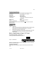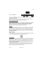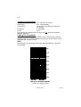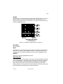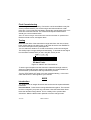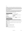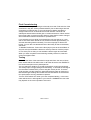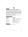
1
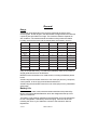
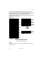
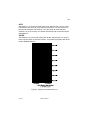
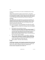
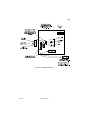
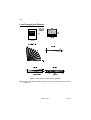
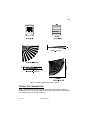
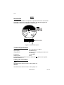
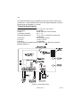
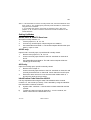
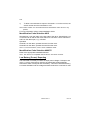
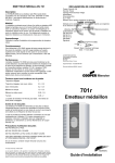
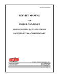
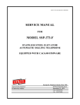
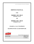
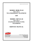
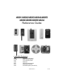
4601/4602/4603/4604/4605/
4606/4608/4609/4624
Reference Guide
Compatible Equipment
4600
4618/9
4612
4660
4611
4613
4675
Wirefree control panel
Eight channel receiver
Two channel receiver
Multiscan
Single channel receiver
Mains light controller
Nursecall system (old version)
496372 Issue 1
1 of 34
General
Range
Transmitter range depends on the receiver aerial and the nature of the
receiving path. These ranges in the table below are approximate and assume
a perfectly flat open field line of sight. The maximum distance depends on
site conditions. The measurements were taken on days when the relative
humidity was less than 50% and the temperature was between 18-25°C.
4600
4660 WITH 4598
4660 WITH 4597
4613, 4611, 4612,
4618 WITH 4598
4613, 4611, 4612,
4618 WITH 4597
4601-50
80
250
600
300
900
4601-60
50
100
250
150
300
4602-55
80
250
600
300
900
4603-60
WITH 4598
80
250
600
300
900
4604-55
50
100
250
150
300
4605-55
50
100
250
150
300
4606-55
80
250
600
300
900
4608-00
50
100
250
150
300
4609-00
50
100
250
150
300
-
500
1000
600
1400
4597 & 10mW MODE
Before installing any radio system Scantronic strongly recommend that you
carry out a radio site survey. To reduce the problems, there are a number of
simple guide-lines that can be followed:
NEVER use the transmitter on a metal surface, including foil-backed plaster
board.
AVOID using the transmitter closer than one metre (3ft) from any computers,
control panels, or other high-powered electrical devices.
AVOID using the transmitter closer than one metre (3ft) from any substantial
water pipes.
Battery Life
The 4601, 4602, 4603, 4604, 4605 and 4606 transmitters are powered by
lithium-manganese-dioxide batteries, which are designed to last up to five
years in normal use.
The battery is permanently soldered to the transmitter and is not designed to
be user-changeable. If the battery needs changing, return the whole unit,
including the case, to your distributor or direct to the Scantronic Service
Department.
2 of 34
496372 Issue 1
4601
BATTERY CARE
DO NOT DESTROY THE BATTERY IN A FIRE.
DO NOT ATTEMPT TO OPEN THE BATTERY.
DO NOT ATTEMPT TO RECHARGE THE BATTERY.
DO NOT HIT THE BATTERY WITH A HEAVY OBJECT.
PAY ATTENTION TO THE METHOD OF DISPOSAL.
If in any doubt contact Scantronic for further disposal information.
4601
Introduction
The 4601-50/60 are narrow band, FM pendant radio transmitters compatible
with any Scantronic 4600 radio receivers, and are designed to be used as an
alarm trigger in dispersed alarm units, nursecall systems and as a panic
button in security and call systems. The 4601-60 can be used as a remote
setting device with the 4600 radio intruder alarm panel.
The units are supplied in an ABS, fire-retardant, plastic housing with a
flexible, tactile, trigger button moulded in neoprene rubber. The non-allergenic, silicon rubber aerial cord of the 4601-50 version enables the user to
wear the unit round his or her neck. The unit has a degree of splash resistance but it is not designed to be immersed in water.
An optional clip (part no. 04630EUR) is available. This clip enables the
transmitter to be clipped to clothing and so avoid the possibility of falling into
liquids or food. The clip uses a longer screw than the normal case screw but
uses the same fixing holes.
To trigger the 4601-50/60 press the orange button on the front of the unit. A
top-facing red LED stays lit for about 4 seconds to confirm transmission.
Technical Specification
Dimensions
h x w x d 58 x 40 x 16mm.
Input supply
3.7V Lithium battery.
Operating temperature
-10° to +55° C.
Frequency
173.225 MHz.
Output power
1mW.
Fully DTI approved to MPT1344. No licence required. For use in
BS6799:1986 systems classes 1-3.
Coding the Transmitter
Open the case, by removing the two cross headed screws at the rear. Turn the
unit over so that the screw holes are underneath. Gently remove the cover,
taking care not to damage the sealant, and place the cover on one side.
496372 Issue 1
3 of 34
4601
The pendants must be coded to match the appropriate receiver. This is
carried out via two sets of small DIL switches.These have only two positions:
UP (or ON), DOWN (or OFF). You can select ANY combination you like
except all switches up (or ON) or all switches down (or OFF).
Ensure that the switches on your receiver match exactly the switch code you
have selected on the transmitter.
4600 Panel
Figure 1. Coding for 4600 Panel
4611/13
Make sure the switches 1-8 and 1-4 on the transmitter, match those on the
receiver exactly.
4 of 34
496372 Issue 1
4601
4612
Set switches 1-8 and 1-2, to the site code of the 4612. Set switches 3-4 on
the first transmitter, to the same as the mode selection switches 3-4 on the
receiver. On the second transmitter, set switches 3-4 to the same as the
mode selection switches 1-2 on the receiver. For further information, refer to
the ‘4612 Installation Manual’.
4618/9
Figure 2. Coding for 4618/9
4660/75
Refer to the appropriate Installation Manual.
496372 Issue 1
5 of 34
4602
Re-assembly
Refit the lid of the case, ensuring that the aerial cord is firmly gripped in the
guides provided and that the sealing “O” ring is correctly seated. Replace the
cross-headed screws into the holes and firmly screw the case together. It is
essential that the screws are tightly secured as the water-resistance is
dependant on this. If necessary, re-seal the aerial Entry/Exit point, with
DOW-CORNING sealant REF: RTV 3145.
ON NO ACCOUNT USE AN ACETIC-ACID BASED SEALANT. (Acetic acid
sealants have a vinegar-like smell).
CAUTION: After accidental immersion in any liquids, the unit should be
opened (as described above), the transmitter board removed
and the whole unit allowed to dry. When completely dry the
unit should be re-assembled, the case re-sealed (as described
in the previous paragraph) and the whole unit tested for correct
operation and range.
If the unit accidentally drops into non-liquid food substances, it
can be carefully wiped clean with a damp cloth. Under no
circumstances should it be washed under running water or
immersed in water or a cleaning fluid.
4602
Introduction
The 4602-55 can be used as a personal attack transmitter to provide remote
protection.
To operate, press the two orange side buttons together. The transmitter does
not signal if you press only one button. Note the black button fitted below the
left-hand orange button. This is a safety lock to prevent false activations.
Slide the black button upwards to lock the orange button.
Technical Specification
Dimensions (body)
Input supply
Frequency
Output power
Operating temperature
h x w x d 102 x 44 x 20mm.
3.7V Lithium battery.
173.225 MHz.
1mW.
-10° to +55°C. Humidity up to 80% (non
condensing).
Fully DTI approved to MPT1344. No licence required. For use in
BS6799:1986 systems classes 1-3.
6 of 34
496372 Issue 1
4602
Coding The Transmitter
Remove the self-tapping screws and carefully ease the top of the case
upwards.
Set the site code on the large 10-way DIL switch as follows: Note that UP is
ON and DOWN is OFF. Do not set all switches to ON or all switches to OFF
or the transmitter will not work correctly.
4600
Set switches 1 to 6 to the site-code of the 4600. Set switches 7-10 and the 2way DIL switch to the zone number.
Figure 3. Coding for 4600
4611/13
Make sure the switches 1-10 and 1-2 on the transmitter match those on the
receiver exactly.
496372 Issue 1
7 of 34
4602
4612
Set switches 1-10 to the site code of the 4612. Set switches 1-2 on the first
transmitter to the same as mode selection switches 3-4 on the receiver. On
the second transmitter set switches 1-2 to the same as mode selection
switches 1-2 on the receiver. For further information refer to the 4612 Installation Manual.
4618/9
Set switches 1 to 8 to the site code of the 4618/9. Set switches 9 to 10 and
the 2-way DIL switch to the zone number. For further information refer to the
4618 Installation Manual.
Figure 4. Coding for 4618/9 modes 1-8
8 of 34
496372 Issue 1
4603
4660/75
Refer to the appropriate installation manual.
Final Commissioning
After coding, switch on the battery. Find switch 2 of the small black 2-way DIL
switch (marked ON/OFF). Set to ON using a terminal screwdriver or ball
point pen. If your unit shows low battery operate the orange buttons five or six
times at five second intervals. The sixth and subsequent transmissions
should give a normal transmission.
Note: DIL switch changes will not take effect until the transmitter is operated twice.
Refit the lid and screws, and tighten them.
Testing
Determine the limits of the transmitter’s range and inform the user of these
limits. Check that the unit will function in all areas where the user EXPECTS
it to function and point out any discrepancies.
You can switch the 4602-55 on so that it transmits a continuous test signal.
This facility helps in range-testing and fault-finding. To activate the test signal
turn the switch marked TEST (on the 2-way DIL switch) to ON.
Figure 5. ON/OFF and Test Switches
To ensure good reception use the Scantronic 4690 field strength meter to
obtain accurate field strength readings and audible and visual indication of
the transmitter’s performance and any interference present.
Turn the TEST switch OFF when you have completed testing, or the transmitter will block ALL radio signals to your receiver!
4603
Introduction
The 4603-60 is a programmable, self contained, multi-function transmitter.
The 4603-60 has a built in battery with up to five years life time and can be
fitted with a range of aerials.
496372 Issue 1
9 of 34
4603
The 4603-60 operates on the DTI-specified frequency for alarm systems, and
can be used as a one or two channel alarm transmitter, Personal Attack
button, door contact, or a Boat/Caravan single zone alarm panel.
Physical Layout
Figure 6. 4603 PCB Layout
Three sets of input terminals occupy the bottom of the circuit card. Immediately above a group of 12 DIL switches provide a means for setting the radio
site code. Above again and to the right a set of six DIL switches control the
general operation of the transmitter. The left side of the circuit card holds a
soldered-in Lithium battery, and the BNC aerial connector.
The 4603-6x series provide three sets of input connectors: A, B, and I/P Con.
Each set of three connectors comprises positive (+Ve), input, and Ground
(Gnd).
The lower left corner of the circuit card holds the lid Tamper switch. The
switch is connected to screw terminals to left of the main inputs which are
isolated from any other circuits on the card. You can connect this output to
your own equipment. The switch contact opens when the lid opens, and
closes when the lid closes.
If you wish to use a keyswitch, Scantronic recommend the Lowe & Fletcher
mini keyswitch, part number 5021052. You can obtain the switch from Lowe
& Fletcher Ltd. (01179 721381).
10 of 34
496372 Issue 1
4603
The BNC connector at the top of the card is a standard Scantronic aerial
connection.
4603-6x series transmitters contain an internal sounder. In all reporting
modes the sounder gives a small click every time one of the inputs A, B or I/P
Con changes state. In addition, in mode 3 the sounder gives a warning tone.
You can silence the sounder using switch 3 (Beep) on the function switches.
Just above the Battery a red LED shows when the unit is transmitting.
Controls
The 12 radio site/unit code switches let you provide each transmitter in an
installation with an unique identity. The transmitter always sends 12 bits of
data at each transmission. Depending on the reporting you select, the last
few bits show the state of the inputs, while the remaining bits shows the
position of the site/unit code switches.
The six function switches control the following functions (from left to right):
1 & 2 Mode 1 and Mode 0. Combined with various connector wiring options
these switches let you select one of 3 reporting modes. See “Programming”.
3
Beep ON/OFF lets you disable the sounder.
4
Fast/Slow scan. When this switch is OFF the unit scans its inputs once
every 100ms. This is fast enough for most types of input except for
very fast push buttons. When this switch is ON the unit scans its inputs
once every 20ms. Note that this can reduce the battery life from a
typical five years to approximately three years. If you change the
speed, push function switch 6 to OFF, wait two or three seconds, and
then turn function switch 6 ON again.
5
Test. This switch overrides switches 1 and 2 (Mode 1 and Mode 0).
When this switch is ON the unit continuously sends the status of the
12 radio site/unit code switches. It is illegal to operate the transmitter
continuously except for occasional tests. Note that leaving function
switch 5 (Test) ON greatly shortens battery life.
6
Battery ON/OFF. This switch isolates the battery.
Power
A permanently connected 3.7V Lithium battery powers the 4603-6x series. With
function switch 4 (Fast/Slow) OFF the battery should last up to five years. With
function switch 4 ON the battery should last up to three years. Note that if you
leave function switch 5 (Test) ON the battery life is greatly reduced.
Do not connect a 12V power source to this unit.
496372 Issue 1
11 of 34
4603
Technical Specification
This section summarises the overall capacities of the 4603-6x series.
Dimensions
h x w x d 152 x 104 x 30mm.
Input supply
Lithium battery.
Battery life
Up to 5 years.
Lid tamper switch
24VDC @ 100mA.
Temperature
-10°C to 55°C. Humidity up to 80% (non
condensing).
Power output
1mW.
Aerial
BNC 50 Ohm impedance.
Frequency 4603UK-60
173.225 MHz.
Fully DTI approved to MPT1344 for alarm use only. No licence required.
BS6799 Class 2.
Programming
General
Mode
1
3
4
Application
Single channel transmitter using Normally Open non-latching input.
This mode can be used for personal attack or call buttons.
Boat/Caravan single zone alarm panel.
Two channel transmitter using Normally Closed inputs. This mode
provides conventional alarm and tamper channels, both with
restore signal.
Mode 1 - Single Channel ‘A Trigger’ (PA Trigger)
Place Mode 0 and Mode 1 switches ON.
Connect a normally open switch from A to Gnd.
Leave inputs B and I/P Con disconnected.
Figure 7. 4603 Mode 1
When A is connected to Gnd, the unit transmits. The unit does not transmit
when the connection opens.
Coding the Transmitter
Set the radio site code (bank of 8 plus 4 DIP switches) as shown for the
4601.
12 of 34
496372 Issue 1
4603
Mode 3 - Boat/caravan Single Zone Alarm Panel
In this mode the 4603-60 can be used as a boat or caravan single zone
alarm panel, which transmits alarm conditions to a remote on-site monitoring
centre.
Place Mode 1 switch ON, Mode 0 switch OFF.
Connect normally closed sensing device between A and Gnd (for example a
movement sensor).
Connect normally closed tamper loop between B and +Ve.
Connect arming switch (key switch or similar) between I/P Con and +Ve.
Figure 8. 4603 Boat Caravan Mode
The 4603-60 is disarmed with the keyswitch ON. While disarmed the unit
monitors input B continuously (24 hour tamper zone) and ignores input A. If
contact B opens the 4603-60 sends a transmission channel B.
The 4603-60 is armed when the keyswitch is OFF. When the switch opens
the 4603-60 sounds the beeper for a fixed 25 second exit period. At the end
of this period the 4603-60 monitors both inputs A and B. If input A opens the
4603-60 sounds the beeper for the 25 second entry period. Unless the unit is
disarmed by closing the keyswitch during the entry period the 4603-60 then
sends a transmission channel A. At the end of the transmission the 4603-60
re-arms input A.
The 4603-60 can be disarmed at any time by closing the keyswitch.
Coding the Transmitter
Set the radio site code (bank of 8 plus 4 DIP switches) as shown for the
4604. Do not use the las two switches in the bank of 4.
Mode 4 - Alarm/Tamper Transmission, With Restore On
Both Channels (Door Contact)
Place Mode 1 switch ON, Mode 0 switch OFF.
Connect a normally closed sensing loop between A and Gnd.
Connect a normally closed tamper loop between B and +Ve.
Link I/P Con to Gnd.
496372 Issue 1
13 of 34
4604
Figure 9. 4603 Mode 4
The unit transmits whenever inputs A or B are either broken or reconnected.
Coding the Transmitter
Set the radio site code (bank of 8 plus 4 DIP switches) as shown for the
4604. Do not use the last two switches in the bank of 4.
Final Commissioning
Push the ON/OFF switch to ON. The unit lights the transmit LED. If the Beep
switch is on then the unit gives a beep while the transmit LED is glowing.
Note that when switching ON the unit you should allow 15 seconds for
internal functional tests before operating the transmitter.
Testing
After completing the initial installation, use the Test switch to check that the
transmitter is within range of the receiver. Turn the Test switch to ON, and
the unit transmits its site/unit code continuously. (The transmit LED lights
during the transmission.) Remember to turn the Test switch OFF when you
have completed testing.
Other Checks
Check that the tamper switch on the case is wired and operates as intended.
If you have installed a keyswitch then check that it works.
4604
Introduction
The 4604-55 is a universal transmitter fitted with an internal reed switch and
supplied with an external magnet. You can use the internal reed contact to
detect doors or windows opening. Four additional terminations let you connect remote magnetic contacts, normally closed (NC) pressure pads, or any
other normally closed switches.
AVOID fitting the transmitter to the outward opening section of a door or
window, the signal can be impaired. Always fit the magnet to such door or
window and the transmitter to the static section.
14 of 34
496372 Issue 1
4604
Technical Specification
Dimensions
Input supply
Temperature
h x w x d 130 x 32 x 23mm.
3.7V Lithium battery.
-10°C to 55°C. Humidity up to 80% (non
condensing).
Frequency
173.225 MHz
Power
1mW
Fully DTI approved to MPT1344 for alarm use only. No licence required.
BS6799 Classes 1-3.
Coding The Transmitter
Set the site code on the large 10-way DIL switch. Note that UP is ON and
DOWN is OFF. Do not set all switches to ON (up) or all OFF (down) or the
transmitter will not work correctly.
4600
Set switches 1 to 6 to the site-code of the 4600. Set switches 7-10 to the
zone number.
Figure 10. Coding for 4600
496372 Issue 1
15 of 34
4604
4618/9
Set switches 1 to 8 to the site code of the 4618/9. Set switches 9 to 10 to the
device number. The alarm channel triggers odd numbered zones. The
tamper channel triggers even number zones. For further information refer to
the 4618 Installation Guide.
Figure 11. Coding for 4618/9 modes 9-13 and 19
4611/4613
Not compatible.
4612
Set switches 1-10 to the site code of the 4612. The tamper channel triggers
channel B. The alarm channel triggers channel A.The 4612 must be in 2channel mode. For further information refer to the 4612 Installation Guide.
4660/75
Refer to the appropriate installation manual.
Switching On
After coding switch on the battery. Find switch 2 of the small black 2-way DIL
switch (marked BATT). Set to ON using a terminal screwdriver or ball point
pen. The transmission LED lights and the unit transmits an open tamper
alarm as the case is open. If your unit shows low battery operate back
tamper switch five or six times at five second intervals. The sixth and subsequent transmissions should give a normal transmission.
16 of 34
496372 Issue 1
4605
Testing
You can switch the 4604-55 on so that it transmits a continuous test signal.
This facility helps in range-testing and fault-finding. To activate the test signal
turn the switch marked TEST (on the 2-way DIL switch) to ON.
Figure 12. ON/OFF and Test Switches
To ensure good reception use the Scantronic 4690 field strength meter to
obtain accurate field strength readings and audible and visual indication of
the transmitter’s performance and any interference present.
Turn the TEST switch OFF when you have completed testing, or the transmitter will block ALL radio signals to your receiver!
Final Commissioning
When you are satisfied with the position and channel transmission characteristics replace the lid. Insert the lid into the bottom of the base. Slowly push
the lid in until it locks into the retaining clip. CAUTION Take care not to bend
or disturb the wire aerial.
Refit the screw and tighten firmly into the base. The red LED lights and the
transmitter sends a closed tamper signal.
Note: DIL switch changes will not take effect until the transmitter is operated twice.
4605
Introduction
The 4605-55 dual function transmitter can be used as a personal attack
transmitter/remote setting device for a 4600 alarm panel, or as a 2-channel
transmitter with the 4612 or 4618/9 receivers and 4660/75 consoles.
To use the 4605 as personal attack button press the two orange side buttons
together. The transmitter does not signal if you press only one button. Note:
the black button fitted below the left-hand orange button. This is a safety lock
to prevent false activations. Slide the black button upwards to lock the orange
button.
496372 Issue 1
17 of 34
4605
Technical Specification
Dimensions
Input supply:
Temperature
h x w x d 102 x 44 x 20mm.
3.7V Lithium battery.
-10°C to 55°C. Humidity up to 80% (non
condensing).
Frequency
173.225 MHz.
Output power
1mW
Fully DTI approved to MPT1344 for alarm use only. No licence required.
BS6799 Classes 1-3.
Coding The Transmitter
Remove the self-tapping screws and carefully ease the top of the case
upwards.
Set the site code on the large 10-way DIL switch. Note that UP is ON and
DOWN is OFF. Do not set all switches to ON or the transmitter will not work
correctly.
4600
Set switches 1 to 6 to the site-code of the 4600. Set switches 7-10 as shown
below. The top button will set or unset the panel. The personal attack buttons
will trip zone 10 (as Personal Attack).
Figure 13. Coding for 4600
4618/9
Set switches 1 to 7 to the site code of the 4618/9. Set switches 8 to 10 to the
zone number. The top button triggers channel A. The side buttons trigger
channel B. For further information refer to the 4618 Installation Guide.
18 of 34
496372 Issue 1
4605
Figure 14. Coding 4618/9 modes 1-8
4611/4613
Not compatible.
4612
Set switches 1-10 to the site code of the 4612. The side buttons trigger
channel B. The top button triggers channel A. The 4612 must be in 2-channel
mode. For further information refer to the 4612 Installation Guide.
4660/75
Refer to the appropriate installation manual.
496372 Issue 1
19 of 34
4606
Final Commissioning
After coding switch on the battery. Find switch 2 of the small black 2-way DIL
switch (marked ON/OFF). Set to ON using a terminal screwdriver or ball
point pen. If your unit shows low battery operate the orange buttons five or six
times at five second intervals. The sixth and subsequent transmissions
should give a normal transmission.
Note: DIL switch changes will not take effect until the transmitter is operated twice.
Refit the lid and screws, and tighten them.
Testing
Determine the limits of the transmitter’s range and inform the user of these
limits. Check that the unit will function in all areas where the user EXPECTS
it to function and point out any discrepancies.
You can switch the 4605-55 on so that it transmits a continuous test signal.
This facility helps in range-testing and fault-finding. To activate the test signal
turn the switch marked TEST (on the 2-way DIL switch) to ON.
Figure 15. ON/OFF and Test Switches
To ensure good reception use the Scantronic 4690 field strength meter to
obtain accurate field strength readings and audible and visual indication of
the transmitter’s performance and any interference present.
Turn the TEST switch OFF when you have completed testing, or the transmitter will block ALL radio signals to your receiver!
4606
Introduction
The 4606-55 has an integral tilt switch and can be used as a personal attack
transmitter.
Personal Attack - Press the two orange side buttons together. The transmitter does not signal if you press only one button. Note the black button fitted
below the left-hand orange button. This is a safety lock to prevent false
activations. Slide the black button upwards to lock the orange button.
20 of 34
496372 Issue 1
4606
Tilt Switch - The buzzer starts a warning tone approximately 12 seconds
after the unit tilts more than 45 degrees from vertical. The warning tone lasts
for 12 seconds while the unit is tilted. At the end of the warning tone the unit
sends an alarm signal to the receiver if it is still tilted. Restore the unit upright
to silence the warning tone.
Manual Over-Ride - Press the grey button on top of the unit to temporarily
disable the tilt switch. After you press the button the unit ignores the tilt switch
for 7 minutes. At the end of that time the unit will sound the buzzer as it
comes back into use. Press the grey button again for another delay. This
facility lets you work without causing false alarms.
Technical Specification
Dimensions
Input supply
Temperature
h x w x d 102 x 44 x 20mm.
3.7V Lithium battery.
-10°C to +55°C. Humidity up to 80% (non
condensing).
Frequency
173.225 MHz.
Power output
1mW.
Fully DTI approved to MPT1344 for alarm use only. No licence required.
BS6799:1986 Classes 1-3.
Coding The Transmitter
Remove the self-tapping screws and carefully ease the top of the case
upwards. Set the site code on the large 10-way DIL switch. Note that UP is
ON and DOWN is OFF. Do not set all switches to ON or the transmitter will
not work correctly.
NOTE: The 4606-55 is not compatible with the 4611/4613 single channel receivers.
4600
Use the same switch settings given for 4604. Tilt is Tamper, the two side
buttons are Alarm.
4612
Set switches as described for the 4605.
4618/9
Set switches as described for the 4605.
4660/75
Refer to the appropriate installation manual.
496372 Issue 1
21 of 34
4606
Final Commissioning
Switch on the battery after setting the site and zone code. Find switch 2 of the
small black 2-way DIL switch (marked ON/OFF). Set to ON using a terminal
screwdriver or ball point pen. If your unit shows low battery operate the
orange buttons five or six times at five second intervals. The sixth and
subsequent transmissions should give a normal transmission. When vertical
the unit may take up to 20 seconds to start up. Note that DIL switch changes
will not take effect until the transmitter is operated twice.
If you switch the unit on while it is horizontal the unit may take up to 7 minutes to arm itself. When armed the unit sounds its buzzer approximately 12
seconds after being tilted horizontally. Turn the unit upright to silence the
buzzer. You can also use the Manual Over-ride facility to silence the buzzer,
see below.
To Disable The Buzzer - Remove the blue jumper (next to the small black 2way DIL switch) to disable the buzzer for security reasons. Park the jumper
on one of the pins so that you can enable the buzzer again at a later date.
When you have completed commissioning carefully refit the lid, insert the
screws and tighten them.
Testing
Determine the limits of the transmitter’s range and inform the user of these
limits. Check that the unit will function in all areas where the user EXPECTS
it to function and point out any discrepancies.
You can switch the 4606-55 on so that it transmits a continuous test signal.
This facility helps in range-testing and fault-finding. To activate the test signal
turn the switch marked TEST (on the 2-way DIL switch) to ON. To ensure
good reception use the Scantronic 4690 field strength meter to obtain accurate field strength readings and audible and visual indication of the transmitter’s performance and any interference present.
Turn the TEST switch OFF when you have completed testing, or the transmitter will block ALL radio signals to your receiver. WARNING the user’s life
may depend on the correct operation of this unit.
22 of 34
496372 Issue 1
4608
4608
Introduction
The 4608 Passive Infra-Red Detector is an indoor only dual element movement detector designed for use with the 4600 control-panel, 4660/75
Multiscan, 4612-2 Channel-or 4618/9-8 Channel-Receiver.
It incorporates a dual element Infra-Red sensor with adjustable interchangeable fresnel lenses which will give 90º wide angle vertical curtain, horizontal
curtain (pet alley) and narrow beam long range detection. The detector has
been designed to have a high signal to noise ratio and RFI immunity. The
PCB is fully ground planed to assist in reducing false alarms. A double edge
signal processing circuit is incorporated for added immunity. The 4608 is
supplied as standard with the wide angle lens.
IMPORTANT: Do not mount the unit closer than 6 inches to the ceiling, otherwise
you will not be able to remove the lid of the unit.
Technical Specification
Curtain lens
Long range lens
Wide angle lens
Voltage
Current
Temperature range
Detection speed
Alarm period
Warm up time
01037 UK-00.
01036 UK-00.
01035 UK-00.
9 Volt Alkaline. MN 1604, 6F22, PP3.
15 Microamps Quiescent (includes PIR and
Radio).
-10º to 50º C. Humidity up to 80% (non
condensing).
0.2 to 3 metres per second.
2s open in Alarm then locked out for 2.5
minutes.
5 minutes from battery insertion.
PIR PCB Layout
Note: To place the “OZW” link, see “Testing”.
496372 Issue 1
23 of 34
4608
Figure 16. 4608 PB Layout
24 of 34
496372 Issue 1
4608
Lens Changing and Patterns
Figure 17. Horizontal Curtain and Long Range
Note 1: Remove PCB and Rotate PCB 90º to the left (anti-clockwise) to use vertical
curtain lens.
496372 Issue 1
25 of 34
4608
Figure 18. Wide Angle and Curtain Lenses.
CODING THE TRANSMITTER
Set the site code on the large 10-way DIL switch. Note that UP is ON and
DOWN is OFF. Do not set all switches to ON (up) or all switches OFF (down)
or the transmitter will not work correctly.
26 of 34
496372 Issue 1
4608
4600
Set switches 1 to 6 to the site-code of the 4600. Set switches 7-10 to the
zone number as shown for the 4604.
4611/4613
Not compatible.
4612
Set switches 1-10 to the site code of the 4612. The tamper channel triggers
channel B. The alarm channel triggers channel A.The 4612 must be in 2channel mode. For further information refer to the 4612 Installation Guide.
4618/9
Set switches 1 to 8 to the site code of the 4618/9. Set switches 9 to 10 to the
device number as shown for the 4605.
4660/75
Refer to the appropriate installation manual.
4608 Transmitter Board
With the Passive Infra-Red Detector sited and set up you can now power
down the unit and install the transmitter board via the 5 molex pins. Take
care to align the pins correctly. Locate the PCB on the small peg on the PIR
Pyro Detector housing and the top plastic clip.
With the transmitter in place set up the site (identification) code and unit
(channel) code on the 10 way DIL switch located to the left of the transmitter
PCB.
Figure 19. 4608 Transmitter PCB
496372 Issue 1
27 of 34
4608
Testing
Figure 20. 4608 Jumpers
Zone Locator Test
To perform a zone locator test, fit the 'OZW' link in the 'Z' position. This will
illuminate the red LED.
With the transmitter board removed, loosen the centre retaining screw and
locate the rear pcb in the uppermost position, then refit the battery and front
lens cover. Move around within the protected area and observe the PIR lens.
Where you can see a bright red light within a lens segment, the PIR is detecting that area. Confirm the coverage as required for other areas. When
complete, ensure the main pcb is in the bottom position.
Walk Test
To perform an engineer walk test of the PIR, fit the 'OZW' link in the 'W'
position.
Replace the transmitter board, refit the battery and front lens cover. Continue
to move around the protected area until the PIR LED illuminates. Following a
short delay, the transmitter will transmit to the receiver/control panel. Confirm
walk testing for the protected area as required.
Normal Operation
To finally set the PIR for normal operation, fit the 'OZW' in the 'O' position.
Replace the transmitter board, refit the battery and the front cover. The PIR
will then take approximately two minutes to stabilise. During normal operation, the PIR will detect an intrusion, transmit a signal, then shut down for 2.5
minutes. If no subsequent movement is detected within the 2.5 minutes, the
PIR will reset ready to activate again. If movement occurs before the two
minute time window, a further two minutes will be added.
Note: The 'OZW' positions may differ on some PIRs. Always follow the positions
shown on the main pcb.
In normal use, the link must be in the 0 position otherwise the battery life will
be reduced by over 90%.
28 of 34
496372 Issue 1
4609
4609
Introduction
The 4609 smoke detector comprises an optical smoke sensor and a radio
transmitter. When the smoke sensor activates, the detector triggers the
transmitter, which in turn signals the control panel.
Figure 21. 4609 PCB Layout
Technical Specification
Dimensions
Input supply:
Temperature
h x w x d 102 x 44 x 20mm.
9V Alkaline PP3.
-10°C to +55°C. Humidity up to 80% (non
condensing).
Frequency
173.225 MHz.
Output power
1mW
Fully DTI approved to MPT1344 for alarm use only. No licence required.
BS6799 Classes 1-3.
Coding the Transmitter
4600
Set switches as shown for 4601. Leave jumper off.
4618/9
Set switches as shown for 4601. Leave jumper off.
496372 Issue 1
29 of 34
4624
4612
Switches 1 to 10 on the receiver match switches 1 to 8 and 1 to 2 on the
4609. Switch 3 on the 4609 matches switch 3 or 1 on the receiver depending
on if it is channel A or B. Jumper J2 matches switch 4 or 2 on the receiver
depending on if it is channel A or B. If J2 is linked then make sure switch is
on. If J2 is unlinked then make sure switch is off.
Figure 22. Coding 4609 for 4612
4611/3
Switches 1 to 8 and 1 to 3 on the receiver match switches 1 to 8 and 1 to 3
on the 4609. Switch 12 on the receiver corresponds to jumper J2 on the
4609. If switch 12 on the receiver is ON then place jumper J2 on the 4609
ON.
4660/75
Refer to installation manual.
Testing
To test if the smoke detector is working press the test button on the unit for
10 seconds. After 10 seconds the unit gives a tone and a transmission.
4624
Introduction
The 4624, 4-Channel Static Transmitter is a long-range telemetry transmitter
which can be used with two normally open and two normally closed inputs or
four normally closed inputs. The transmitter is powered from a 12VDC power
source and incorporates a constant input power monitoring circuit and low
battery indication, and is housed in an aluminium case.
30 of 34
496372 Issue 1
4624
The 4624 transmitter is fully compatible with 4618 and 4619 receivers and
provides two - channel indication with 4612 and 4660/75 Multiscan receivers.
Output power is switchable 1 or 10mW.
Technical Specifications
Dimensions
Power supply
Current
Low battery threshold
Operating temperature
h x w x d 135 x 142 x 33mm.
10-15 VDC.
20 MA quiescent. 60 mA in alarm.
9.5 +/- 1 V
-10° to +55° C. Humidity up to 80% (non
condensing).
Transit time
2.5 seconds (1 event).
R.F. level
1 mW to 10 mW.
Frequency
173.225 MHz.
Fully DTI approved to MPT1344 for alarm use only. No licence required.
BS6799 Classes 1-3.
Figure 23. 4624 PCB Layout
496372 Issue 1
31 of 34
4624
Note 1. If the transmitter is used for normally closed units, the 4618/9 Receiver must
be in mode 14. Any unused inputs (channels) must be linked out, unless when
using the 4612 or 4660/75.
2. If a normally open input is to be used on channels A and C, then minijumpers J7, J8, J9 and J10 must be removed and mode 15 selected on the
4618/9 Receiver.
Setting Up Modes
4618/9, 4612 & 4660/75 Receivers.
All Inputs normally closed A - D.
1.
Fit mini-jumpers J7, J8, J9, J10.
2.
Link out any unused inputs, unless using 4612 or 4660/75.
3.
Use 4618/9 Receiver Mode 14. The 4618/9 outputs will follow the input
state i.e. open or close.
4618/9 only.
Inputs A and C normally open, Inputs B and D normally closed.
1.
Remove mini-jumpers J7, J8, J9, J10.
2.
Connect normally open devices to the N.O. terminals on channels A
and C.
3.
Use 4618/9 Receiver Mode15. The odd number outputs will be momentary (5 seconds hold).
4612 only.
Input A is normally open, input B is normally closed.
1.
Remove mini-Jumper J7.
2.
Connect normally open devices to the N.O. terminals on channel A and
normally closed devices to channel B. Leave channels C and D open.
3.
Ensure the 4612 receiver is in two channel mode. Mode switch 6, 7
and 8 on the 4612 are as you select.
Identification Code Selection 4618/9
It is very important when using the 4624 Transmitters that the channel
numbers 1-4, 5-8 are set up correctly. This is decided by using the identification code switch number 8 as follows:
a)
System Code - switches 1-7 set the same on both transmitter and the
receiver.
b)
To allow one 4624 to output to channels 1 - 4 on the receiver, set
switch number 8 on the transmitter to ‘On’.
32 of 34
496372 Issue 1
4624
c)
To allow a second 4624 to output to channels 5 - 8 on the receiver, set
switch number 8 on the transmitter to ‘Off’.
Note: Switch number 8 on the 4618/9 Receiver Identification switch can be in any
position.
For more information refer to 4618 Installation Guide.
Identification Code Selection 4612
Set switches 1-8 on the 4624, to the site code of the 4612. Set switches 9-10
on the 4612 to off and set the mode switch for 2-Channel. Leave channels C
and D on the 4624 open, e.g., unlinked.
Operation
Channel A on the 4624, operates channel A on the 4612.
Channel B on the 4624, operates channel B on the 4612.
Note : For more information, refer to ‘4612 Installation Guide’.
Identification Code Selection 4660/75
Refer to the appropriate Installation Manual.
Note : The 4624 is not compatible with the 4600 or 4611/4613 receivers.
Low Battery (Power) Reporting
The transmitter constantly monitors the input power voltage. If it drops to 9.5
volts +/-1 volt for more than 2 minutes, the transmitter will automatically
transmit the state of all inputs and ‘low battery’. This will be transmitted every
2 minutes thereafter until the voltage has been restored to a nominal 12 volts.
496372 Issue 1
33 of 34
34 of 34
496372 Issue 1