1
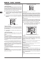
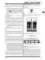
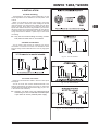
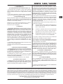
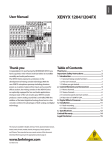
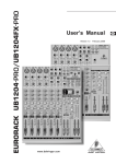
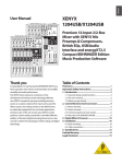
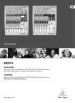
1204/1204FX XENYX Users Manual Version 1.0 January 2006 XENYX 1204/1204FX IMPORTANT SAFETY INSTRUCTIONS DETAILED SAFETY INSTRUCTIONS: 1) Read these instructions. 2) Keep these instructions. 3) Heed all warnings. 4) Follow all instructions. CAUTION: To reduce the risk of electric shock, do not remove the top cover (or the rear section). No user serviceable parts inside; refer servicing to qualified personnel. 5) Do not use this apparatus near water. 6) Clean only with dry cloth. 7) Do not block any ventilation openings. Install in accordance with the manufacturers instructions. WARNING: To reduce the risk of fire or electric shock, do not expose this appliance to rain and moisture. The apparatus shall not be exposed to dripping or splashing and no objects filled with liquids, such as vases, shall be placed on the apparatus. This symbol, wherever it appears, alerts you to the presence of uninsulated dangerous voltage inside the enclosurevoltage that may be sufficient to constitute a risk of shock. This symbol, wherever it appears, alerts you to important operating and maintenance instructions in the accompanying literature. Please read the manual. 8) Do not install near any heat sources such as radiators, heat registers, stoves, or other apparatus (including amplifiers) that produce heat. 9) Do not defeat the safety purpose of the polarized or grounding-type plug. A polarized plug has two blades with one wider than the other. A grounding type plug has two blades and a third grounding prong. The wide blade or the third prong are provided for your safety. If the provided plug does not fit into your outlet, consult an electrician for replacement of the obsolete outlet. 10) Protect the power cord from being walked on or pinched particularly at plugs, convenience receptacles, and the point where they exit from the apparatus. 11) Only use attachments/accessories specified by the manufacturer. 12) Use only with the cart, stand, tripod, bracket, or table specified by the manufacturer, or sold with the apparatus. When a cart is used, use caution when moving the cart/apparatus combination to avoid injury from tip-over. 13) Unplug this apparatus during lightning storms or when unused for long periods of time. 14) Refer all servicing to qualified service personnel. Servicing is required when the apparatus has been damaged in any way, such as power supply cord or plug is damaged, liquid has been spilled or objects have fallen into the apparatus, the apparatus has been exposed to rain or moisture, does not operate normally, or has been dropped. 15) CAUTION - These service instructions are for use by qualified service personnel only. To reduce the risk of electric shock do not perform any servicing other than that contained in the operation instructions unless you are qualified to do so. 2 TABLE OF CONTENTS XENYX 1204/1204FX 1. INTRODUCTION ........................................................................................................ 4 1.1 General mixing console functions .................................................................................................................... 5 1.2 The users manual ........................................................................................................................................... 5 1.3 Before you get started ....................................................................................................................................... 5 1.3.1 Shipment ................................................................................................................................................ 5 1.3.2 Initial operation ....................................................................................................................................... 5 1.3.3 Online registration .................................................................................................................................. 5 2. CONTROL ELEMENTS AND CONNECTORS .......................................................... 5 2.1 Mono channels ................................................................................................................................................. 5 2.1.1 Microphone and line inputs ................................................................................................................... 5 2.1.2 Equalizer ................................................................................................................................................. 6 2.1.3 Aux sends ............................................................................................................................................... 6 2.1.4 Routing switch, solo and channel fader ................................................................................................ 6 2.2 Stereo channels ................................................................................................................................................ 7 2.2.1 Channel inputs ....................................................................................................................................... 7 2.2.2 Equalizer stereo channels ..................................................................................................................... 7 2.2.3 Aux sends stereo channels ................................................................................................................... 7 2.2.4 Routing switch, solo and channel fader ................................................................................................ 7 2.3 Connector panel and main section .................................................................................................................. 7 2.3.1 Aux sends 1 and 2 .................................................................................................................................. 7 2.3.2 Aux send connectors 1 and 2 ................................................................................................................ 7 2.3.3 Stereo aux return connectors ................................................................................................................. 7 2.3.4 Stereo aux return .................................................................................................................................... 8 2.3.5 Tape input / tape output .......................................................................................................................... 8 2.3.6 Level meter and monitoring ................................................................................................................... 8 2.3.7 Alt 3-4 and main mix fader ..................................................................................................................... 9 2.4 Rear view of 1204FX/1204 ................................................................................................................................ 9 2.4.1 Main mix outputs, Alt 3-4 outputs and control room outputs ................................................................. 9 2.4.2 Voltage supply, phantom power and fuse ............................................................................................ 10 3. DIGITAL EFFECTS PROCESSOR .......................................................................... 10 4. INSTALLATION ........................................................................................................ 11 4.1 Rack mounting ................................................................................................................................................ 11 4.2 Cable connections .......................................................................................................................................... 11 4.2.1 Audio connections ................................................................................................................................ 11 5. SPECIFICATIONS .................................................................................................... 12 6. WARRANTY ............................................................................................................. 13 3 XENYX 1204/1204FX 1. INTRODUCTION FOREWORD Dear Customer, Im sure youre one of those people who have devoted themselves body and soul to your chosen area and no doubt this has made you an expert in your field. Well, for over 30 years, my passion has been music and electronics. This not only led me to establish BEHRINGER, but also enabled me to share my enthusiasm with our employees. During all the years Ive been involved with studio technology and end users, I have developed a feel for the things that really count, such as sound quality, reliability and ease of use. What is more, I have always had the desire to test the boundaries of what is technically feasible. It was precisely this motivation that prompted me to start work on a new series of mixing consoles. Since our XENYXs had already set new standards world-wide, I knew the development objectives behind the next generation of mixing consoles had to be especially ambitious. Thus, the concept and design of the new XENYX mixing consoles bear my signature. The design work, the entire circuit diagram and PCB development, and even the mechanical concepts are my own work. I carefully selected each individual component with the aim of pushing the mixing consoles combining analog and digital technologies to their limits. My vision was to enable you, the user, to give free rein to your true potential and creativity. The result is mixing consoles that combine incredible performance with intuitive operability. They cannot fail to impress with their extremely flexible routing possibilities plus a fantastic wealth of functions. Innovative technologies, such as the completely new XENYX Mic Preamps and the British EQs, guarantee optimum sound quality. And extraordinarily high-quality components provide unrivalled reliability, even under extreme loads. Thanks to the quality and ease of use of your new XENYX mixing console youll soon come to appreciate that I, both personally and in my capacity as musician and sound engineer, put you, the end user, first and that these products were only possible because of the passion and the attention to detail that went into them. Thank you for the confidence you have placed in us by purchasing the XENYX mixing console. I should also like to thank all those who, with their personal commitment and passion, have helped me create this impressive series of mixing consoles. Kindest regards, Congratulations! In purchasing the BEHRINGER XENYX you have acquired a mixer whose small size belies its incredible versatility and audio performance. The XENYX Series represents a milestone in the development of mixing console technology. With the new XENYX microphone preamps including phantom power as an option, balanced line inputs and a powerful effects section, the mixing consoles in the XENYX Series are optimally equipped for live and studio applications. Owing to state-of-the-art circuitry your XENYX console produces a warm analog sound that is unrivalled. With the addition of the latest digital technology these best-in-class consoles combine the advantages of both analog and digital technology. The microphone channels feature high-end XENYX Mic Preamps that compare well with costly outboard preamps in terms of sound quality and dynamics and boast the following features: s 130 dB dynamic range for an incredible amount of headroom s A bandwidth ranging from below 10 Hz to over 200 kHz for crystal-clear reproduction of even the finest nuances s The extremely low-noise and distortion-free circuitry guarantees absolutely natural and transparent signal reproduction s They are perfectly matched to every conceivable microphone with up to 60 dB gain and +48 volt phantom power supply s They enable you to use the greatly extended dynamic range of your 24-bit/192 kHz HD recorder to the full, thereby maintaining optimal audio quality British EQ The equalizers used for the XENYX Series are based on the legendary circuitry of top-notch consoles made in Britain, which are renowned throughout the world for their incredibly warm and musical sound character. Even with extreme gain settings these equalizers ensure outstanding audio properties. Multi-effects processor Additionally, your XENYX mixing console has an effects processor with 24-bit A/D and D/A converters included, which gives you 100 presets producing first-class reverb, delay and modulation effects plus numerous multi-effects in excellent audio quality. The XENYX mixing consoles are equipped with a state-of-theart switched-mode power supply (SMPS). Unlike conventional circuitry an SMPS provides an optimum supply current regardless of the input voltage. And thanks to its considerably higher efficiency a switched-mode power supply uses less energy than conventional power supplies. USB/Audio interface The USB interface supplied with the unit is a perfect match for the XENYX Series and serves as a powerful recording interface to your PC or MAC®. It supports the digital transmission of signals on up to four channels with max. 48 kHz and extremely low latency. When wired to the CD/TAPE INPUT and OUTPUT connectors, the interface transfers the stereo mix from the console directly to a computer. Both the recording signal and the playback signal from the computer can be monitored at the same time. In this way, you can use several recording runs to produce complete multi-track recordings. CAUTION! + Uli Behringer 4 We should like to draw your attention to the fact that extreme volumes may damage your hearing and/or your headphones or loudspeakers. Turn the MAIN MIX faders and phones control in the main section fully down before you switch on the unit. Always be careful to set the appropriate volume. 1. INTRODUCTION 1.1 General mixing console functions + A mixing console fulfils three main functions: s Signal processing: Preamplification, level adjustment, mixing of effects, frequency equalization. s Signal distribution: Summing of signals to the aux sends for effects processing and monitor mix, distribution to one or several recording tracks, power amp(s), control room and 2-track outputs. s Mix: Setting the volume level, frequency distribution and positioning of the individual signals in the stereo field, level control of the total mix to match the recording devices/ crossover/power amplifier(s). All other mixer functions can be included in this main function. The interface of BEHRINGER mixing consoles is optimized for these tasks enabling you to easily keep track of the signal path. 1.2 The users manual The users manual is designed to give you both an overview of the controls, as well as detailed information on how to use them. In order to help you understand the links between the controls, we have arranged them in groups according to their function. If you need to know more about specific issues, please visit our website at http://www.behringer.com, where youll find explanations of e.g. effects and dynamics applications. + The block diagram supplied with the mixing console gives you an overview of the connections between the inputs and outputs, as well as the associated switches and controls. For the moment, just try and trace the signal path from the microphone input to the aux send 1 connector. Dont be put off by the huge range of possibilities; its easier than you think! If you look at the overview of the controls at the same time, youll be able to quickly familiarize yourself with your mixing console and youll soon be making the most of all its many possibilities. XENYX 1204/1204FX Please ensure that only qualified people install and operate the mixing console. During installation and operation, the user must have sufficient electrical contact to earth, otherwise electrostatic discharges might affect the operation of the unit. 1.3.3 Online registration Please do remember to register your new BEHRINGER equipment right after your purchase by visiting www.behringer.com (alternatively www.behringer.de) and kindly read the terms and conditions of our warranty carefully. Should your BEHRINGER product malfunction, our goal is to have it repaired as quickly as possible. To arrange for warranty service, please contact the retailer from whom the equipment was purchased. Should your BEHRINGER dealer not be located in your vicinity, you may directly contact one of our subsidiaries. Corresponding contact information is included in the original equipment packaging (Global Contact Information/European Contact Information). Should your country not be listed, please contact the distributor nearest you. A list of distributors can be found in the support area of our website (www.behringer.com). Registering your purchase and equipment with us helps us process your repair claims quicker and more efficiently. Thank you for your cooperation! 2. CONTROL ELEMENTS AND CONNECTORS This chapter describes the various control elements of your mixing console. All controls, switches and connectors will be discussed in detail. 2.1 Mono channels 2.1.1 Microphone and line inputs 1.3 Before you get started 1.3.1 Shipment Your mixing console was carefully packed in the factory to guarantee safe transport. Nevertheless, we recommend that you carefully examine the packaging and its contents for any signs of physical damage, which may have occurred during transit. + If the unit is damaged, please do NOT return it to us, but notify your dealer and the shipping company immediately, otherwise claims for damage or replacement may not be granted. 1.3.2 Initial operation Be sure that there is enough space around the unit for cooling purposes and to avoid over-heating please do not place your mixing console on high-temperature devices such as radiators or power amps. The console is connected to the mains via the supplied cable. The console meets the required safety standards. Blown fuses must only be replaced by fuses of the same type and rating. + Please note that all units must be properly grounded. For your own safety, you should never remove any ground connectors from electrical devices or power cables, or render them inoperative. Fig. 2.1: Connectors and controls of mic/line inputs MIC Each mono input channel offers a balanced microphone input via the XLR connector and also features switchable +48 V phantom power supply for condenser microphones. The XENYX preamps provide undistorted and noise-free gain as is typically known only from costly outboard preamps. + Please mute your playback system before you activate the phantom power supply to prevent switch-on thumps being directed to your loudspeakers. Please also note the instructions in chapter 2.4.2 Voltage supply, phantom power and fuse. LINE IN Each mono input also features a balanced line input on a 1/4" connector. Unbalanced devices (mono jacks) can also be connected to these inputs. 2. CONTROL ELEMENTS AND CONNECTORS 5 XENYX 1204/1204FX + Please remember that you can only use either the microphone or the line input of a channel at any one time. You can never use both simultaneously! LOW CUT The mono channels of the mixing consoles have a high-slope LOW CUT filter for eliminating unwanted, low-frequency signal components (75 Hz, 18 dB/octave). TRIM Use the TRIM control to adjust the input gain. This control should always be turned fully counterclockwise whenever you connect or disconnect a signal source to one of the inputs. 2.1.2 Equalizer All mono input channels include a 3-band equalizer. All bands provide boost or cut of up to 15 dB. In the central position, the equalizer is inactive. The circuitry of the British EQs is based on the technology used in the best-known top-of-the-line consoles and providing a warm sound without any unwanted side effects. The result are extremely musical equalizers which, unlike simple equalizers, cause no side effects such as phase shifting or bandwidth limitation, even with extreme gain settings of ±15 dB. + If you press the MUTE/ALT 3-4 switch, aux send 1 is muted, provided that it is switched postfader. However, this does not affect the aux send 2 of the 1204FX. AUX 1 (MON) In the 1204FX, aux send 1 can be switched pre-fader and is thus particularly suitable for setting up monitor mixes. In the 1204, the first aux send is labeled MON and is permanently switched pre-fader. PRE When the PRE switch is pressed, aux send 1 is sourced prefader. AUX 2 (FX) The aux send labeled FX is for sending to effects devices and is thus set up to be post-fader. In the 1204FX, the FX send is routed directly to the built-in effects processor. + + If you wish to use the internal effects processor, the STEREO AUX RETURN 2 connectors should not be in use. 1204FX: you can also connect an external effects processor to aux send 2, however the internal effects module will be muted. 2.1.4 Routing switch, solo and channel fader Fig. 2.2: The equalizer of the input channels The upper (HI) and the lower band (LO) are shelving filters that increase or decrease all frequencies above or below their cut-off frequency. The cut-off frequencies of the upper and lower band are 12 kHz and 80 Hz respectively. The mid band is configured as a peak filter with a center frequency of 2.5 kHz. 2.1.3 Aux sends Fig. 2.3: The AUX SEND controls in the channel strips Aux sends take signals via a control from one or more channels and sum these signals to a so-called bus. This bus signal is sent to an aux send connector and then routed, for example, to an active monitor speaker or an external effects device. The return from an external effect can then be brought back into the console via the aux return connectors. For situations which require effects processing, the aux sends are usually switched post-fader so that the effects volume in a channel corresponds to the position of the channel fader. If this were not the case, the effects signal of the channel would remain audible even when the fader is turned to zero. When setting up a monitor mix, the aux sends are generally switched to pre-fader; i.e. they operate independently of the position of the channel fader. Both aux sends are mono, are sourced after the equalizer and offer up to +15 dB gain. 6 Fig. 2.4: Panorama and routing controls PAN The PAN control determines the position of the channel signal within the stereo image. This control features a constant-power characteristic, which means the signal is always maintained at a constant level, irrespective of position in the stereo panorama. MUTE/ALT 3-4 You can use the MUTE/ALT 3-4 switch to divert the channel from the main mix bus to the Alt 3-4 bus. This mutes the channel from the main mix. MUTE-LED The MUTE LED indicates that the relevant channel is diverted to the submix (Alt 3-4 bus). CLIP-LED The CLIP LED lights up when the input signal is driven too high. In this case, turn down the TRIM control and, if necessary, check the setting of the channel EQ. 2. CONTROL ELEMENTS AND CONNECTORS XENYX 1204/1204FX SOLO The SOLO switch (1204FX only) is used to route the channel signal to the solo bus (Solo In Place) or to the PFL bus (Pre Fader Listen). This enables you to monitor a channel signal without affecting the main output signal. The signal you hear is sourced either before (PFL, mono) or after (solo, stereo) both the pan control and the channel fader (see chapter 2.3.6 Level meters and monitoring). 2.3.1 Aux sends 1 and 2 The channel fader determines the level of the channel signal in the main mix (or submix). Fig. 2.6: AUX SEND controls of the main section 2.2 Stereo channels A channel signal is routed to aux send bus 1 if the AUX 1 control is turned up on the corresponding channel. 2.2.1 Channel inputs AUX SEND 1 (MON) The AUX SEND control MON acts as master control for aux send 1 and determines the level of the summed signal. In the 1204FX, the MON control is called AUX SEND 1. AUX SEND 2 (FX) Similarly, the FX control (AUX SEND 2) determines the level for aux send 2. Fig. 2.5: Stereo channel inputs and LEVEL switch Each stereo channel has two balanced line level inputs on 1/4" connectors for left and right channels. If only the connector marked L is used, the channel operates in mono. Stereo channels are designed to handle typical line level signals. Both inputs can also be used with unbalanced jacks. LEVEL For level matching, the stereo inputs feature a LEVEL switch which selects between +4 dBu and -10 dBV. At -10 dBV (home-recording level), the input is more sensitive than at +4 dBu (studio level). SOLO You can use the SOLO switch (1204FX only) to separately monitor the aux sends via the CONTROL ROOM/PHONES outputs and check these with the level meters. + If you want to monitor the signal of just one AUX bus, none of the other SOLO SWITCHES should be pressed and the MODE switch must be in the SOLO position (not pressed down). 2.3.2 Aux send connectors 1 and 2 2.2.2 Equalizer stereo channels The equalizer of the stereo channels is, of course, stereo. The filter characteristics and crossover frequencies are the same as those of the mono channels. A stereo equalizer is always preferable to two mono equalizers if frequency correction of a stereo signal is needed. There is often a discrepancy between the settings of the left and the right channels when using separate equalizers. 2.2.3 Aux sends stereo channels In principle, the aux sends of the stereo channels function in just the same way as those of the mono channels. As aux send paths are always mono, the signal on a stereo channel is first summed to mono before it reaches the aux bus. 2.2.4 Routing switch, solo and channel fader BAL The function of the BAL(ANCE) control corresponds to the PAN control in the mono channels. Fig. 2.7: Aux send connectors AUX SEND 1 If you use aux send 1 pre-fader, you would usually connect the AUX SEND 1 connector to monitors via a power amp (or an active monitor system). If you use aux send 1 post-fader, proceed as described under aux send 2. AUX SEND 2 The AUX SEND 2 connector outputs the signal you picked up from the individual channels using the FX control. You can connect this to the input of an effects device in order to process the FX bus signal. Once an effects mix is created, the processed signal can then be routed from the effects device output back into the STEREO AUX RETURN connectors. 2.3.3 Stereo aux return connectors The balance control determines the relative proportion between the left and right input signals before both signals are routed to the main stereo mix bus. The MUTE/ALT 3-4 switch, the MUTE-LED, the CLIP-LED, the SOLO switch and the channel fader function in the same way as the mono channels. 2.3 Connector panel and main section Whereas it was useful to trace the signal flow from top to bottom in order to gain an understanding of the channel strips, we now look at the mixing console from left to right. The signals are, so to speak, collected from the same point on each of the channel strips and then routed to the main section all together. Fig. 2.8: Stereo aux return connectors STEREO AUX RETURN 1 The STEREO AUX RETURN 1 connectors generally serve as the return path for the effects mix generated using the postfader aux send. This is where you connect the output signal of the external effects device. If only the left connector is used, the AUX RETURN automatically operates in mono. 2. CONTROL ELEMENTS AND CONNECTORS 7 XENYX 1204/1204FX + You can also use these connectors as additional line inputs. 2.3.5 Tape input / tape output STEREO AUX RETURN 2 The STEREO AUX RETURN 2 connectors serve as the return path for the effects mix generated using the FX control. If these connectors already function as additional inputs, you can route the effects signal back into the console via a different channel, with the added benefit that the channel EQ can be used to adjust the frequency response of the effects return signal. + + In this instance, the FX control of the channel being used as an effects return should be turned fully counterclockwise, otherwise feedback problems could occur! If you wish to use the internal effects processor, no connectors should be plugged into STEREO AUX RETURN 2. 2.3.4 Stereo aux return Fig. 2.10: 2-track connectors CD/TAPE INPUT The CD/TAPE INPUT RCA connectors are provided for connecting a 2 track machine (e.g. DAT recorder). They can also be used as stereo line input. Alternatively, the output signal of a second XENYX or BEHRINGER ULTRALINK PRO MX882 can also be connected. If you connect a hi-fi amplifier with a source selection switch to the CD/TAPE INPUT, you can easily switch between additional sources (e.g. cassette recorder, CD player, etc.). CD/TAPE OUTPUT These connectors are wired in parallel with the MAIN OUT and carry the main mix signal (unbalanced). Connect the CD/TAPE OUTPUT to the inputs of your recording device. The final output level can be adjusted via the high-precision MAIN MIX fader. + Fig. 2.9: Stereo aux return controls STEREO AUX RETURN 1 STEREO AUX RETURN 1 is a stereo control which determines the level of the signal in the main mix. If STEREO AUX RETURN 1 is used as effects return, you can add the effects signal to any dry channel signal. + If you connect a compressor or a noise gate after the 2-track output, the faders will probably not be able to create a satisfactory fade-out effect. 2.3.6 Level meter and monitoring In this instance, the effects device should be set at 100% effect. STEREO AUX RETURN MON The STEREO AUX RETURN MON control has a special function: it can be used to add an effect to a monitor mix. For example: Monitor mix with effect In this instance, the effects device should be set up as follows: AUX SEND 2 is connected to the L/Mono input of your effects device, while its outputs are connected to STEREO AUX RETURN 1. Connect the amplifier of your monitor system to AUX SEND 1. The AUX SEND 1 master control determines the volume of the monitor mix. You can now use the STEREO AUX RETURN MON control to adjust the level of the effects signal routed to the monitor mix. You can easily use the headphones distribution amplifier BEHRINGER POWERPLAY PRO HA4600/HA4700/HA8000 to provide you with four (or eight with the HA8000) stereo headphone mixes for your studio. STEREO AUX RETURN 2 (FX) The STEREO AUX RETURN 2 control determines the level of signals fed into the AUX RETURN 2 connectors which are routed to the main mix. MAIN MIX/ALT 3-4 The MAIN MIX/ALT 3-4 switch routes the signal connected to STEREO AUX RETURN 2 to either main mix (not pressed) or submix (Alt 3-4, pressed). Fig. 2.11: Control room/phones section, level meter CD/TAPE The TAPE switch routes the signal from the TAPE IN connectors to the level meter, the CONTROL ROOM OUT outputs and the PHONES connectorthis is a simple way to check recorded signals via monitor speakers or headphones. ALT 3-4 Similarly, the ALT 3-4 switch routes the signal from the Alt 3-4 bus to the same path for monitoring purposes. MAIN MIX The MAIN MIX switch sends the main mix signal to the abovementioned outputs and to the level meter. PHONES/CTRL R(oom) Use this control to set control room output level and headphones volume respectively. CD/TAPE TO MAIN When the CD/TAPE TO MAIN switch is depressed, the 2track input is routed to the main mix and thus serves as an additional input for tape machines. You can also connect MIDI instruments or other signal sources here that do not require any further processing. At the same time, this switch disables the main mix to tape output link. POWER The blue POWER LED indicates that the device is switched on. 8 2. CONTROL ELEMENTS AND CONNECTORS XENYX 1204/1204FX +48 V The red +48 V LED lights up when the phantom power supply is switched on. The phantom power supply is necessary for condenser microphones and is activated using the switch on the rear of the device. + Please do not connect microphones to the mixer (or the stagebox/wallbox) while the phantom power supply is switched on. Connect microphones before you switch on the power supply. In addition, the monitor/PA loudspeakers should be muted before you activate the phantom power supply. After switching on, wait approx. one minute to allow for system stabilization. MAIN SOLO (1204FX only) The MAIN SOLO LED lights up as soon as a channel or aux send solo switch is pressed. The MODE switch also has to be set at Solo. PFL (1204FX only) The PFL LED indicates that the peak meter is set to PFL mode. Fig. 2.12: PHONES connector LEVEL METER The high-precision level meter accurately displays the appropriate signal level. PHONES You can connect headphones to this 1/4" TRS connector. The signal on the PHONES connection is sourced from the control room output. LEVEL SETTING: When recording to a digital device, the recorders peak meter should not exceed 0 dB. This is because, unlike analog recordings, slightly excessive levels can create unpleasant digital distortion. 2.3.7 Alt 3-4 and main mix fader When recording to an analog device, the VU meters of the recording machine should reach approx. +3 dB with lowfrequency signals (e.g. kick drum). Due to their inertia VU meters tend to display too low a signal level at frequencies above 1 kHz. This is why, for example, a Hi-Hat should only be driven as far as -10 dB. Snare drums should be driven to approx. 0 dB. + The peak meters of your XENYX display the level virtually independent of frequency. A recording level of 0 dB is recommended for all signal types. MODE (1204FX only) The MODE switch determines whether the channels SOLO switch operates as PFL (Pre Fader Listen) or as solo (Solo In Place). PFL To activate the PFL function, depress the MODE switch. The PFL function should, as a rule, be used for gain setting purposes. The signal is sourced pre-fader and assigned to the mono PFL bus. In the PFL setting, only the left side of the peak meter operates. Drive the individual channels to the 0 dB mark of the VU meter. Solo When the MODE switch is not depressed, the stereo solo bus is active. Solo is short for Solo In Place. This is the customary method for listening to an individual signal or to a group of signals. As soon as a solo switch is pressed, all channels in the control room (and headphones) that have not been selected are muted thereby retaining stereo panning. The solo bus can carry the output signals of the channel pan controls, the aux sends and the stereo line inputs. The solo bus is, as a rule, switched postfader. + The PAN control in the channel strip offers a constant power characteristic. This means that the signal is always at a constant level, irrespective of its position in the stereo panorama. If the PAN control is moved fully left or right from center, the level increases by 4 dB in that channel. This ensures that, when set in the center, the audio signal is not louder. For this reason, with the solo function activated (Solo in Place), audio signals from the channels with PAN controls that have not been moved fully to the left or right are displayed at a lower volume than in the PFL function. As a rule, solo signals are monitored via the control room outputs and headphones connector and are displayed by the level meters. If a solo switch is pressed, the signals from the tape input, Alt 3-4 and main mix are blocked from the control room outputs, the headphone connector and the level meter. Fig. 2.13: Alt 3-4 and main mix fader Use the high-precision quality faders to control the output level of the Alt 3-4 subgroup and main mix. 2.4 Rear view of 1204FX/ 1204 2.4.1 Main mix outputs, Alt 3-4 outputs and control room outputs Fig. 2.14: Main mix outputs, Alt 3-4 outputs and control room outputs MAIN OUTPUTS The MAIN outputs carry the MAIN MIX signal and are on balanced XLR connectors with a nominal level of +4 dBu. ALT 3-4 OUTPUTS The ALT 3-4 outputs are unbalanced and carry the signals of the channels that you have assigned to this group using the MUTE switch. This can be used to route a subgroup to a further mixing console for example, or or it could be used as a recording output working in tandem with the main output. This means you could record to four tracks simultaneously. The icing on the cake, so to speak, is that you could connect Y-cables to these four outputs and then connect your 8-track recorder in such a way that you have 2 x 4 tracks (e.g. channel 1 feeds track 1 and track 2, etc.). In the first recording pass, you record on tracks 1, 2. CONTROL ELEMENTS AND CONNECTORS 9 XENYX 1204/1204FX 3, 5 and 7 and in the second pass, on tracks 2, 4, 6 and 8. CONTROL ROOM OUTPUTS The control room output is normally connected to the monitor system in the control room and provides the stereo mix or, when required, the solo signal. 3. DIGITAL EFFECTS PROCESSOR 2.4.2 Voltage supply, phantom power and fuse Fig. 2.15: Voltage supply and fuse FUSE HOLDER The console is connected to the mains via the cable supplied which meets the required safety standards. Blown fuses must only be replaced by fuses of the same type and rating. IEC MAINS RECEPTACLE The mains connection is via a cable with IEC mains connector. An appropriate mains cable is supplied with the equipment. POWER Use the POWER switch to power up the mixing console. PHANTOM The PHANTOM switch activates the phantom power supply for the XLR connectors of the mono channels which is required to operate condenser microphones. The red +48 V LED lights up when phantom power is on. As a rule, dynamic microphones can still be used with phantom power switched on, provided that they are wired in a balanced configuration. In case of doubt, contact the microphone manufacturer! + + After the phantom power supply has been switched on, do not connect microphones to the mixer (or the stagebox/wallbox). Connect the microphones before you switch phantom power on. In addition, the monitor/PA loudspeakers should be muted before activating the phantom power supply. After switching on, wait approx. one minute to allow the system to stabilize. Caution! You must never use unbalanced XLR connectors (PIN 1 and 3 connected) on the MIC input connectors if you want to use the phantom power supply. SERIAL NUMBER Please note the important information on the serial number given in chapter 1.3.3. 10 Fig. 3.1: Digital effects module (only 1204FX) 24-BIT MULTI-EFFECTS PROCESSOR Here you can find a list of all presets stored in the multi-effects processor. This built-in effects module produces high-grade standard effects such as reverb, chorus, flanger, delay and various combination effects. The integrated effects module has the advantage of requiring no wiring. This way, the danger of creating ground loops or uneven signal levels is eliminated at the outset, completely simplifying the handling. These effect presets are designed to be added to dry signals. If you move the FX TO MAIN control, you mix the channel signal (dry) and the effect signal. This also goes for mixing effects signals with the monitor mix. The main difference is that the mix ratio is adjusted using the FX TO MON control. Of course, a signal has to be fed into the effects processor via the FX control in the channel strip for both applications. + On the following page, you will find an illustration showing how to connect your foot switch correctly. LEVEL The LED level meter on the effects module should display a sufficiently high level. Take care to ensure that the clip LED only lights up at peak levels. If it is lit constantly, you are overloading the effects processor and this could cause unpleasant distortion. The FX control (AUX SEND 2) determines the level that reaches the effects module. PROGRAM You can select the effect preset by turning the PROGRAM control. The display flashes the number of the current preset. To recall the selected preset, press the button; the flashing stops. You can also recall the selected preset with the foot switch. 3. DIGITAL EFFECTS PROCESSOR XENYX 1204/1204FX 4. INSTALLATION 4.1 Rack mounting The packaging of your mixing console contains two 19" rack mount wings which can be installed on the side panels of the console. Before you can attach the rack mount wings to the mixing console, you need to remove the screws holding the left and right side panels. Use these screws to fasten the two wings onto the console, being careful to note that each wing fits a specific side. With the rack mount wings installed, you can mount the mixing console in a commercially available 19" rack. Be sure to allow for proper air flow around the unit, and do not place the mixing console close to radiators or power amps, so as to avoid overheating. + Fig. 4.2: XLR connections Only use the screws holding the mixing console side panels to fasten the 19" rack mounts. 4.2 Cable connections You will need a large number of cables for the various connections to and from the console. The illustrations below show the wiring of these cables. Be sure to use only high-grade cables. Fig. 4.3: 1/4" TS connector Fig. 4.1: 1/4" TS connector for foot switch 4.2.1 Audio connections Please use commercial RCA cables to wire the 2-track inputs and outputs. Fig. 4.4: 1/4" TRS connector You can, of course, also connect unbalanced devices to the balanced input/outputs. Use either mono plugs, or ensure that ring and sleeve are bridged inside the stereo plug (or pins 1 & 3 in the case of XLR connectors). + Caution! You must never use unbalanced XLR connectors (pin 1 and 3 connected) on the MIC inputs if you intend to use the phantom power supply. Fig. 4.5: 1/4" TRS connector for headphones 4. INSTALLATION 11 XENYX 1204/1204FX 5. SPECIFICATIONS Mono inputs Microphone inputs (XENYX Mic Preamp) Type XLR, electronically balanced, discrete input circuit Mic E.I.N. (20 Hz - 20 kHz) @ 0 W source resistance -134 dB / 135.7 dB A-weighted @ 50 W source resistance -131 dB / 133.3 dB A-weighted @ 150 W source resistance -129 dB / 130.5 dB A-weighted Frequency response <10 Hz - 150 kHz (-1 dB), <10 Hz - 200 kHz (-3 dB) Gain range Max. input level Impedance Signal-to-noise ratio +10 to +60 dB +12 dBu @ +10 dB gain approx. 2.6 kW balanced 110 dB / 112 dB A-weighted (0 dBu In @ +22 dB gain) Distortion (THD+N) 0.005% / 0.004% A-weighted Line input Type Impedance Gain range Max. input level Fade-out attenuation1 (Crosstalk attenuation) Main fader closed Channel muted Channel fader closed Frequency response Microphone input to main out <10 Hz - 90 kHz <10 Hz - 160 kHz Stereo inputs Type 1/4" TS connector, unbal. approx. 120 W +22 dBu Headphones output Type Max. output level 1/4" TRS connector, unbalanced +19 dBu / 150 W (+25 dBm) DSP Converter Sampling rate 90 dB 89.5 dB 89 dB Power supply Mains voltage Power consumption Fuse Mains connection Physical 1204FX Dimensions (H x W x D) +0 dB / -1 dB +0 dB / -3 dB Weight (net) EQ mono channels Low Mid High 80 Hz / ±15 dB 2.5 kHz / ±15 dB 12 kHz / ±15 dB EQ stereo channels Low Mid High 80 Hz / ±15 dB 2.5 kHz / ±15 dB 12 kHz / ±15 dB Aux sends Type Impedance Max. output level 1/4" TS connector, unbalanced approx. 120 W +22 dBu 12 Control room outputs Type Impedance Max. output level 1/4" TRS connector electronically balanced approx. 20 kW balanced 10 kW unbalanced -10 to +40 dB 30 dBu Impedance Max. input level Impedance Max. input level XLR, electronically balanced approx. 240 W bal. / 120 W unbal. +28 dBu Main mix system data 2 Noise Main mix @ -oo, Channel fader -oo Main mix @ 0 dB, Channel fader -oo Main Mix @ 0 dB, Channel fader @ 0 dB 1/4" TRS connector, electronically balanced approx. 20 kW +22 dBu Stereo aux returns Type Main outputs Type Impedance Max. output level 1/4" TRS connector, electronically balanced approx. 20 kW bal. / 10 kW unbal. +22 dBu 1204 Dimensions (H x W x D) Weight (net) 24-bit Texas Instruments TM 24-bit Sigma-Delta, 64/128-times oversampling 40 kHz -105 dB / -108 dB A-weighted -95 dB / -97 dB A-weighted -82,5 dB / -85 dB A-weighted 100 - 240 V~, 50/60 Hz 40 W 100 - 240 V~: T 1.6 A H 250 V Standard IEC receptacle approx. 97 mm (3 7/8") x 247 mm (9 11/16") x 334 mm (13 5/32") approx. 2.60 kg (5 3/4 lbs) approx. 97 mm (3 7/8") x 247 mm (9 11/16") x 328 mm (13") approx. 2.56 kg (5 5/8 lbs) Measuring conditions: 1: 1 kHz rel. to 0 dBu; 20 Hz - 20 kHz; line input; main output; unity gain. 2: 20 Hz - 20kHz; measured at main output. Channels 1 - 4 unity gain; EQ flat; all channels on main mix; channels 1/3 as far left as possible, channels 2/4 as far right as possible. Reference = +6 dBu. BEHRINGER is constantly striving to manintain the highest professional standards. As a result of these efforts, modifications may be made from time to time to existing products without prior notice. Specifications and appearance may differ from those listed or illustrated. 5. SPECIFICATIONS XENYX 1204/1204FX 6. WARRANTY § 1 OTHER WARRANTY RIGHTS AND NATIONAL LAW 1. This warranty does not exclude or limit the buyers statutory rights provided by national law, in particular, any such rights against the seller that arise from a legally effective purchase contract. 2. The warranty regulations mentioned herein are applicable unless they constitute an infringement of national warranty law. 2. If the product needs to be modified or adapted in order to comply with applicable technical or safety standards on a national or local level, in any country which is not the country for which the product was originally developed and manufactured, this modification/adaptation shall not be considered a defect in materials or workmanship. The warranty does not cover any such modification/adaptation, irrespective of whether it was carried out properly or not. Under the terms of this warranty, BEHRINGER shall not be held responsible for any cost resulting from such a modification/adaptation. Please do remember to register your new BEHRINGER equipment right after your purchase by visiting www.behringer.com (alternatively www.behringer.de) and kindly read the terms and conditions of our warranty carefully. 3. Free inspections and maintenance/repair work are expressly excluded from this warranty, in particular, if caused by improper handling of the product by the user. This also applies to defects caused by normal wear and tear, in particular, of faders, crossfaders, potentiometers, keys/buttons, tubes, guitar strings, illuminants and similar parts. Registering your purchase and equipment with us helps us process your repair claims quicker and more efficiently. 4. Damages/defects caused by the following conditions are not covered by this warranty: Thank you for your cooperation! s improper handling, neglect or failure to operate the unit in compliance with the instructions given in BEHRINGER user or service manuals. s connection or operation of the unit in any way that does not comply with the technical or safety regulations applicable in the country where the product is used. s damages/defects caused by force majeure or any other condition that is beyond the control of BEHRINGER. § 2 ONLINE REGISTRATION § 3 WARRANTY 1. BEHRINGER (BEHRINGER International GmbH including all BEHRINGER subsidiaries listed on the enclosed page, except BEHRINGER Japan) warrants the mechanical and electronic components of this product to be free of defects in material and workmanship for a period of one (1) year* from the original date of purchase, in accordance with the warranty regulations described below. If the product shows any defects within the specified warranty period that are not excluded from this warranty as described under § 5, BEHRINGER shall, at its discretion, either replace or repair the product using suitable new or reconditioned parts. In the case that other parts are used which constitute an improvement, BEHRINGER may, at its discretion, charge the customer for the additional cost of these parts. 2. If the warranty claim proves to be justified, the product will be returned to the user freight prepaid. 3. Warranty claims other than those indicated above are expressly excluded. § 4 RETURN AUTHORIZATION NUMBER 1. To obtain warranty service, the buyer (or his authorized dealer) must call BEHRINGER (see enclosed list) during normal business hours BEFORE returning the product. All inquiries must be accompanied by a description of the problem. BEHRINGER will then issue a return authorization number. 2. Subsequently, the product must be returned in its original shipping carton, together with the return authorization number to the address indicated by BEHRINGER. 5. Any repair or opening of the unit carried out by unauthorized personnel (user included) will void the warranty. 6. If an inspection of the product by BEHRINGER shows that the defect in question is not covered by the warranty, the inspection costs are payable by the customer. 7. Products which do not meet the terms of this warranty will be repaired exclusively at the buyers expense. BEHRINGER will inform the buyer of any such circumstance. If the buyer fails to submit a written repair order within 6 weeks after notification, BEHRINGER will return the unit C.O.D. with a separate invoice for freight and packing. Such costs will also be invoiced separately when the buyer has sent in a written repair order. § 6 WARRANTY TRANSFERABILITY This warranty is extended exclusively to the original buyer (customer of retail dealer) and is not transferable to anyone who may subsequently purchase this product. No other person (retail dealer, etc.) shall be entitled to give any warranty promise on behalf of BEHRINGER. § 7 CLAIM FOR DAMAGES 3. Shipments without freight prepaid will not be accepted. § 5 WARRANTY REGULATIONS 1. Warranty services will be furnished only if the product is accompanied by a copy of the original retail dealers invoice. Any product deemed eligible for repair or replacement under the terms of this warranty will be repaired or replaced. Failure of BEHRINGER to provide proper warranty service shall not entitle the buyer to claim (consequential) damages. In no event shall the liability of BEHRINGER exceed the invoiced value of the product. * Customers in the European Union please contact BEHRINGER Germany Support for further details. Technical specifications and appearance subject to change without notice. The information contained herein is correct at the time of printing. The names of companies, institutions or publications pictured or mentioned and their respective logos are registered trademarks of their respective owners. Their use neither constitutes a claim of the trademarks by BEHRINGER® nor affiliation of the trademark owners with BEHRINGER®. BEHRINGER® accepts no liability for any loss which may be suffered by any person who relies either wholly or in part upon any description, photograph or statement contained herein. Colours and specification may vary slightly from product. Products are sold through our authorised dealers only. Distributors and dealers are not agents of BEHRINGER® and have absolutely no authority to bind BEHRINGER® by any express or implied undertaking or representation. No part of this manual may be reproduced or transmitted in any form or by any means, electronic or mechanical, including photocopying and recording of any kind, for any purpose, without the express written permission of BEHRINGER Spezielle Studiotechnik GmbH. BEHRINGER® is a registered trademark. ALL RIGHTS RESERVED. © 2006 BEHRINGER Spezielle Studiotechnik GmbH, Hanns-Martin-Schleyer-Str. 36-38, 47877 Willich-Münchheide II, Germany. Tel. +49 2154 9206 0, Fax +49 2154 9206 4903 6. WARRANTY 13