1
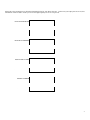
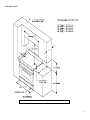
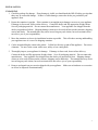
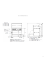
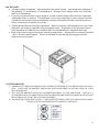
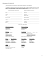
INSTALLATION MANUAL Free Standing Ranges RCS RNB RPB Heritage Classic Platinum™ Series 1 BLUESTAR® INSTALLATION INSTRUCTIONS FOR THE FREE STANDING RANGE FOR THE HOME MODELS RCS, RPB, RNB, Heritage, Platinum THIS APPLIANCE WAS DESIGNED FOR EASE OF INSTALLATION AND OPERATION. HOWEVER, WE RECOMMEND THAT YOU READ ALL SECTIONS OF THIS MANUAL BEFORE YOU BEGIN INSTALLATION. INSTALLATION MUST BE PERFORMED BY AN APPROVED GAS INSTALLER OR GAS SERVICE TECHNICIAN OR THE WARRANTY IS VOID. IN THE COMMONWEALTH OF MASSACHUSETTS A LICENSED PLUMBER OR GAS FITTER CAPABLE OF REVIEWING AND PERFORMING THE MANUFACTURER’S INSTALLATION CHECKLIST SHOULD INSTALL THIS APPLIANCE. THE INSTALLATION CHECKLIST IS INCLUDED AT THE REAR OF THIS BOOKLET. DO NOT REMOVE PERMANENTLY AFFIXED LABELS, WARNINGS OR DATA PLATES FROM YOUR APPLIANCE. THIS MAY VOID THE MANUFACTURER’S WARRANTY AND/OR HINDER EFFECTIVE SERVICING AND MAINTENANCE. THESE INSTRUCTIONS ARE TO REMAIN WITH THE APPLIANCE AND THE CONSUMER IS TO RETAIN THEM FOR FUTURE REFERENCE. WARNING: If the information in this manual is not followed exactly, a fire or explosion may result causing property damage, personal injury or death. - Do not store or use gasoline or other flammable vapors and liquids in the vicinity of this or any other appliance. WHAT TO DO IF YOU SMELL GAS Do not try to light any appliance Do not touch or activate any electrical switch Do not use any phone in your building Immediately call your gas supplier from a neighbor’s phone. Follow the gas supplier’s instructions. If you cannot reach your gas supplier, call the fire department Installation and service must be performed by a qualified installer, service agency or the gas supplier. - NOTE: WARRANTY SERVICE MUST BE PERFORMED BY AN AUTHORIZED SERVICE AGENT. YOU MAY REQUEST WARRANTY SERVICE BY CALLING 800-449-8691. YOU MAY ALSO REQUEST SERVICE VIA THE INTERNET BY SUBMITTING THE SERVICE REQUEST FORM AT WWW.BLUESTARCOOKING.COM In the Commonwealth of Massachusetts, gas connections must be performed by a licensed plumber or licensed gas fitter. © Copyright 2014 Prizer –Painter Stove Works, Inc. All specifications are subject to change without prior notification 2 Please take a few moments now to fill in the information below for your future reference. In the event you require parts or service, this information will be needed to ensure you receive the highest quality service we can provide. DATE OF PURCHASE DEALER’S NAME DEALER’S ADDRESS DATE OF INSTALLATION INSTALLER’S NAME INSTALLER’S ADDRESS MODEL NUMBER SERIAL NUMBER 3 SAFETY INSTRUCTIONS To avoid personal injury or property damage, please read and follow these important safety precautions. 1. Before any maintenance or repairs are performed, disconnect the appliance from the electric supply. 2. Your appliance should be installed by a qualified gas installation technician. Have the technician show you the exact location of the gas shutoff valve on the incoming gas line so you know how to turn off the gas if necessary. 3. In the event of a power failure, do not attempt to operate the appliance or light any of the burners. This is a gas fired appliance that employs electrical components such as the ignition and safety devices. 4. Do not attempt to repair or replace any part of this appliance unless specifically instructed to do so by this manual. In-warranty service must be performed by an authorized service agency. 5. Do not store flammable materials on or near the appliance. Keep the appliance area clean and free of combustible materials, gasoline and other flammable vapors and liquids. A check before each use to determine that no hazardous materials are in the area is recommended. 6. The push-to-turn control knobs on this appliance are designed to be child-safe, however, not a guarantee of safe operation. Children should not be left alone or unattended in the kitchen while the appliance is in use. 7. This appliance should not be operated without a properly sized and operational ventilation hood. 8. The ventilation and flue ways of this appliance must remain unobstructed at all times. 9. Additional care should be exercised if your appliance is equipped with a high-shelf. During heavy or continued use this shelf may become hot. Do not place combustible materials or plastics on this shelf. 10. Do not store items of interest to children above the appliance. Children, as well as adults, should never be allowed to sit, stand, or climb on any part of the appliance. Serious injury may occur. 11. Never leave the appliance unattended during use. Boil-overs may occur, causing spills which may ignite. 12. Do not use water on grease fires. Never pick up a flaming pan. It is recommended you purchase a multi-purpose dry chemical or foam-type fire extinguisher for your home. Store it in close proximity to your appliance. 13. If you are flaming liquor or other spirits, and you're appliance is installed under a vent hood, TURN THE FAN OFF. The draft created could cause the flames to spread out of control. 14. For your safety, never use your appliance or any other cooking appliance as a space heater to warm or heat the room. 15. Use only dry potholders. Moist or damp potholders on hot surfaces may result in steam burns. Do not allow potholders to touch hot burner areas. Do not use a towel or other bulky material as a potholder. 16. To reduce the risk of burns, ignition of flammable materials, and spillage, the handle of any pot or pan should be positioned so that it does not extend over adjacent burners or the front of the appliance. Proposition 65 Warning WARNING AND IMPORTANT SAFETY NOTICE RELATING TO CARBON MONOXIDE: The California Safe Drinking Water and Toxic Enforcement Act requires the Governor of California to publish a list of substances known to the state to cause cancer, birth defects or other reproductive harm, and requires businesses to warn customers of potential exposure to such substances. Carbon Monoxide is one such substance known to the state to cause birth defects or other reproductive harm. Operation of this product could expose you to carbon monoxide if the air shutter are not adjusted properly. Directions on how to adjust the air shutters properly can be found in more detail in the MAINTENANCE section of the Use & Care Manual. 4 SITE PREPARATION This appliance has been designed to be installed directly against rear walls and side base cabinets. It cannot be installed directly against tall side cabinets, side walls, tall appliances or base cabinets extending beyond 24 inches [610 mm]. Side trims must be at least 11/16 inch [17.5 mm] above the adjoining counter top surfaces. Any openings in the back wall or the floor of the installation site must be sealed. Each gas appliance shall be located with respect to building construction and other equipment to permit access to the appliance. Such access and clearance is necessary for cleaning and servicing. Due to its size and weight, a rolling lift jack, air sled or pallet jack should be used to move the appliance into position. Do not push against the edges or sides of any appliance in an attempt to slide it into position. Although all sharp metal parts are de-burred during the manufacturing process, serious injury could occur if the appliance were to move suddenly while being positioned. We recommend you use gloves during the installation process. Do not use the kick panel or oven door handle to push or pull the appliance into position. For optimum performance the appliance should be leveled during installation. A carpenter-type level should be placed on the unit three ways: side to side, front to back, and diagonally. Appliances on bullet legs may be leveled by screwing the various leg assemblies in or out. If the appliance is installed in an island or cabinet cut-out, the edges should be shimmed with small metal coupons. Any opening in the wall behind the range and in the floor under the range should be sealed. 5 CLEARANCES The maximum depth of cabinets installed above cooling tops be 13” 6 INSTALLATION UNPACKING 1. Check the package for damage. If any damage is visible you should mark the Bill of Lading you sign that there may be concealed damage. If there is visible damage, contact the dealer you purchased your appliance from. 2. Ensure the container is upright. If the container is not upright major damage can occur to your appliance. If damage is discovered, do not refuse delivery. Contact the dealer and file appropriate freight claims. Save all packaging material. Do not contact the manufacturer. Your appliance was shipped from the dealer you purchased it from. Shipping damage claims are to be resolved between the customer, shipping carrier and dealer. The manufacturer may assist in resolving any such claims, but such assistance does not relieve you of your responsibility. 3. Move the container as close to its installation location as possible. This will reduce moving and handling your appliance once it is out of its shipping container. 4. Cut the straps holding the carton to the palette. Lift the box directly up and off the appliance. Do not use a hammer. Do not cut the carton with a razor, utility or box cutting knife. 5. Thoroughly inspect your appliance for damage. If damage is discovered, do not refuse delivery. Contact the dealer and file appropriate freight claims. Save all packaging material. Do not contact the manufacturer. Your appliance was shipped from the dealer you purchased it from. Shipping damage claims are to be resolved between the customer, shipping carrier and dealer. The manufacturer may assist in resolving any such claims, but such assistance does not relieve you of your responsibility. 6. Remove and unpack any accessories shipped with your appliance. Make sure no hardware or accessories are left to be disposed of unintentionally. 7 RANGE DIMENSIONS 8 CASTERS Appliance is for use only with the specific legs or casters specified by the manufacturer When casters are employed on two or more legs, installation must be on 1/8” (2mm) thick commercial grade vinyl composition floor finishing materials or equivalent. The load rating of each swivel caster is 250 lbs. 24”, 30”, 36” units have 4 casters (1,000lbs). 48” and 60” units come with 6 casters (1,500lbs). Total weight of appliances 24”: 275, 30”: 300, 36”: 375, 48”: 550, 60”: 700 When using casters: (1) the installation shall be made with a connector that complies with the Standard for Connectors for Movable Gas Appliances, ANSI Z21.69, CSA6.16, and a quick disconnect device that complies with the Standard for quick-disconnect devices for use with gas fuel, ANSI Z21.41, CSA 6.9, (2) that adequate means shall be provided to limit the movement of the appliance without depending on the connector and the quick-disconnect device or its associated piping to limit the appliance movement; (3) where the restraining means shall be attached to the appliance; and (4) that if disconnection of the restraint is necessary, ensure the restraint is reconnected after the appliance has been returned to its original installed position. 9 BACKGUARD All ranges require a backguard. Most models have the option of using: grate height trim; island trim; 6” inch standard; 17” inch hi-back; 24” inch high shelf. Heritage Classic models require a 24” inch high shelf for all installations. If you are using an island trim or grate height, a six inch clearance between the back of the range and a combustible surface is required. If an island trim is to be used without this six inch clearance, the back wall must be constructed using non-combustible and heat resistant materials that extend below the top surface of the range a minimum of six inches. All backguards follow the same basic installation. Remove rear grates, slide backguard over rear of unit, align holes, use hardware supplied to fasten backguard to unit. A minimum of six sheet metal screws (more depending on width) are to be installed, three on each end and more along the bottom edge. Remove the two rear ring grate/top grates from the cooktop surface. Sheet metal screws must be installed - down - into the cooktop support. Screws are installed on each end ring grate/top grate position. Replace the removed grates. ANTI-TIP BRACKET UNDER NO CICUMSTANCES SHOULD YOU STAND ON THE DOOR OF YOUR RANGE OR USE IT AS A STEP. YOUR ANTI-TIP BRACKET SHOULD BE INSTALLED PRIOR TO INSTALLATION OF YOUR BLUESTAR RANGE. THE ANTI-TIP BRACKET MUST BE ANCHORED SECURELY TO THE SUB-FLOOR. CONTACT A QUALIFIED FLOOR COVERING INSTALLER FOR THE BEST PROCEDURE OF DRILLING MOUNTING HOLES THROUGH YOUR TYPE OF FLOOR COVERING. BRACKET SHOULD BE INSTALLED 1 ½” FROM THE LEFT SIDE OF THE UNIT AND FLUSH AGAINST THE WALL WITH FASTENER HOLES CLOSEST TO THE WALL. 10 GAS CONNECTIONS This appliance must be installed by an approved installer or a gas technician 1. The installation of this appliance must conform with all applicable local codes. In the absence of local codes, the installation must conform to the latest level of the National Fuel Gas Code, ANSI Z223.1/NFPA 54. In Canada, the installation must be in accordance with the current CAN/CGA B149.1 and B149.2. 2. Maximum gas must not exceed 14 inches water column (wc) or 1/2 psi. 3. This appliance can be configured to work with either natural gas or LP gas. Verify that the appliance and the incoming gas supply match. Check the rating plate. 4. Leak testing of the appliance shall be conducted according to the manufacturer’s instructions. 5. Incoming gas pressure should be 1 in wc above appliance rating of 5 inches wc and 10 inches wc. 6. The gas supply line must be the same size or larger than the gas inlet of the appliance. Your appliance has either a ½” NPT or ¾” NPT gas inlet connection. It is recommended that the supply line be ¼” NPT larger than the gas inlet of the appliance. If the gas supply line is not sufficiently sized, the operation of the appliance may be affected. 7. Sealant used on pipe joints must be resistant to LP gas. 8. An installer provided manual shut-off valve must be installed in the gas supply line ahead of the appliance. This shut-off must be easily accessible in case of emergency. 9. All gas cooking equipment must have a pressure regulator on the incoming service line for safe and efficient operation. This appliance is equipped with such a gas pressure regulator. Incoming gas pressure should be checked with a manometer. The correct manifold pressure for natural gas is 5.0” wc. For LP gas the correct manifold pressure is 10” wc. 10. Incoming line pressure upstream of the appliance should be 1.0” wc greater than the operating manifold pressure. Service pressure may fluctuate for a variety of reasons. Under no circumstances should the factory installed regulator be removed or by-passed. 11. The factory installed pressure regulator will withstand an input pressure of ½ PSI (12” wc). If the incoming pressure exceeds the maximum rating, a step-down regulator is required. 12. The appliance and its individual shut-off valve must be disconnected from the gas supply line during any pressure testing in excess of ½ PSI [3.5 kPa]. 13. The appliance must be disconnected from the gas supply by closing its individual shut-off during any pressure testing less than ½ PSI [3.5 kPa]. 14. Check to see that all installer supplied pipes and fittings are clear of debris, threading chips or other foreign particles before connecting the appliance to the supply line. Such particles will clog orifices and/or valves when pressure is applied. Service to clean such clogs is not covered by your warranty. 15. The incoming gas supply is brought from the inlet pipe. This is the only connection required via the installer-supplied shut-off valve. 16. If the appliance is to be installed with flexible couplings and/or a “quick disconnect” the installer must use a commercially approved AGA Design Certified flexible connector at least ½” NPT that complies with ANSI Z21.41. In Canada, the connector must comply with CAN 16.10-88 and the “quick disconnect” device must comply with CAN 16.19M-79 and installed with a strain relief device. 17. Before putting the appliance into service test all gas connections for leaks. When pressure testing systems do not exceed ½ psi or else damage will occur to the regulator. To test, use a soapy water solution. DO NOT USE AN OPEN FLAME TO CHECK FOR LEAKS. Such a procedure is dangerous, and it may not detect all the small leaks that a soapy solution will. 18. Air shutter adjustments are preset at the factory. These adjustments may need to be redone and/or fine tuned by the installer. These adjustments are normal. They are the responsibility of the qualified installer and are not covered by your warranty. 19. A gas type conversion performed in the field may void your warranty. Contact your dealer for information regarding the conversion from one type of gas supply to another. 11 20. Burner head locations are specific to the valves on the front of the unit. If burner heads are removed for cleaning or other purposes, they must be re-installed in the same location they were removed from. Failure to do so may result in a burner that will not light or possibly have a high flame. 12 ELECTRICAL CONNECTIONS 1. The installation of this appliance must conform with all applicable local codes. In the absence of local codes, the installation must conform to the latest level of the National Electric Code, and ANSI/NFPA 70. 2. This appliance is equipped with a standard three prong polarized, NEMA 5-15P line cord to be plugged into a 120 Volt 15 AMP outlet. 3. Removing the grounding prong from the plug will void the manufacturer’s warranty. 4. The cord exits the appliance at the lower rear toward the right (viewed from front) side. 5. If the electrical supply is not turned on or is interrupted, the appliance will not operate. 6. The applicable wiring diagram for this appliance is affixed to the appliance. 7. The circuit where you plug your appliance must be grounded and polarized. 8. We recommend the circuit for your appliance be a non-GCFI dedicated line. 9. It is recommended that your circuit never include a microwave oven. SERVICE If the appliance requires service, to gain access to control valves or switches behind front control panel please follow the below steps: Remove knobs. Remove screws attaching control panel to base structure located under the top grates. Remove screw from each bottom end of control panel. Pull control panel forward to remove. REPLACEMENT PARTS Replacement Parts can be acquired by calling Customer Service at 1-800-449-8691 or Fax (610) 376-2596. WARNING This appliance is equipped with a three-pronged grounding plug for your protection against shock hazard and should be plugged directly into a properly grounded receptacle. Do NOT cut or remove the grounding prong from this plug. If the appliance is not grounded or its polarity is reversed, severe shock hazards can exist. VENTILATION Proper ventilation is highly important for good operation. This appliance must be installed under a ventilation hood. We recommend that the hood should be six inches [150 mm] wider than the appliance, however, it is not a requirement. A strong exhaust fan can create a vacuum in the room. For proper air balance, work with your dealer and/or contactor to properly size your hood and its exhaust fan. It is recommended that your exhaust hood be powerful enough to move a minimum of 300 cfm. IMPORTANT ALL GAS BURNERS NEED SUFFICIENT AIR TO OPERATE AND LARGE OBJECTS SHOULD NOT BE PLACED IN FRONT OF THIS APPLIANCE WHICH WOULD OBSTRUCT THE AIR FLOW THROUGH THE FRONT. OBJECTS SHOULD NOT BE PLACED ON THE REAR BACKGUARD WHILE IN USE. THIS COULD OBSTRUCT THE VENTING SYSTEM OF THE OVEN’S FLUE PRODUCTS. 13 PERFORMANCE CHECKLIST This checklist has been developed to assure proper installation of your appliance. To validate your warranty you must mail or fax this form within 15 days of installation and a copy of your receipt to: Warranty Department, Prizer-Painter Stove Works Inc., 600 Arlington Street, Reading, PA 19611, or Fax (610) 376-2596. Failure to do so will void the warranty. Customer Information (Please Print) Product Information (Please Print) Name:________________________________________ Model No: ________________________________ Address: ______________________________________ Serial No: _________________________________ City: _________________________________________ Purchase Date: _____________________________ State, Zip Code: ________________________________ Installation Date: ___________________________ e-mail: _______________________________________ Installer’s Name: ___________________________ Telephone: ____________________________________ Company: _________________________________ Dealer: _______________________________________ Telephone: ________________________________ CHECK ALL THAT APPLY Appearance and Aesthetics Exterior Top section Oven interior Broiler pan set Electrical Connection Correct voltage Grounded outlet Polarized outlet No GFCI Installation Proximity to cabinets Level Backguard in place Ventilation system Read User Manual Review safety instructions Gas Connection Ignition Flame Adjustment Top Burners Top Burners Griddle Griddle Char Broiler Char Broiler Oven Burner Oven Burner Infrared Broiler Infrared Broiler Air/Gas Mixture Top Burners Griddle Char Broiler Oven Burner Infrared Broiler Controls Burner knobs Thermostats Convection oven fan & switch Oven light switch Oven Door Alignment Door seal Hinges Verify fuel—_____Nat _____LP Gas shut-off present and accessible Supply line properly sized Supply pressure checked Operating pressure checked All connections checked for leaks Valve Operation Top Burners Griddle Char Broiler Oven Burner Infrared Broiler 14