1
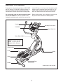
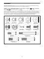
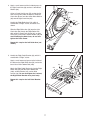
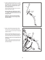
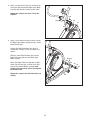
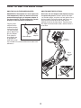
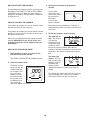
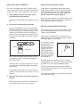
Model No. PFEVEL96010.1
Serial No.
Write the serial number in the
space above for reference.
USERʼS MANUAL
Serial Number Decal
(on underside of frame)
QUESTIONS?
If you have questions, or if there are
missing parts, please contact us:
UK
Call: 08457 089 009
From Ireland: 053 92 36102
Website: www.iconsupport.eu
E-mail: [email protected]
Write:
ICON Health & Fitness, Ltd.
c/o HI Group PLC
Express Way
Whitwood, West Yorkshire
WF10 5QJ
UK
AUSTRALIA
Call: 1-800-237-173
E-mail:
[email protected]
CAUTION
Read all precautions and instructions in this manual before using
this equipment. Keep this manual
for future reference.
www.iconeurope.com
TABLE OF CONTENTS
WARNING DECAL PLACEMENT . . . . . . . . . . . . . . . . . . . . . . . . . . . . . . . . . . . . . . . . . . . . . . . . . . . . . . . . . . . . . .2
IMPORTANT PRECAUTIONS . . . . . . . . . . . . . . . . . . . . . . . . . . . . . . . . . . . . . . . . . . . . . . . . . . . . . . . . . . . . . . . .3
BEFORE YOU BEGIN . . . . . . . . . . . . . . . . . . . . . . . . . . . . . . . . . . . . . . . . . . . . . . . . . . . . . . . . . . . . . . . . . . . . . .4
ASSEMBLY . . . . . . . . . . . . . . . . . . . . . . . . . . . . . . . . . . . . . . . . . . . . . . . . . . . . . . . . . . . . . . . . . . . . . . . . . . . . . . .5
HOW TO USE THE CHEST PULSE SENSOR . . . . . . . . . . . . . . . . . . . . . . . . . . . . . . . . . . . . . . . . . . . . . . . . . .12
HOW TO USE THE ELLIPTICAL . . . . . . . . . . . . . . . . . . . . . . . . . . . . . . . . . . . . . . . . . . . . . . . . . . . . . . . . . . . . .13
MAINTENANCE AND TROUBLESHOOTING . . . . . . . . . . . . . . . . . . . . . . . . . . . . . . . . . . . . . . . . . . . . . . . . . . .20
EXERCISE GUIDELINES . . . . . . . . . . . . . . . . . . . . . . . . . . . . . . . . . . . . . . . . . . . . . . . . . . . . . . . . . . . . . . . . . . .22
PART LIST . . . . . . . . . . . . . . . . . . . . . . . . . . . . . . . . . . . . . . . . . . . . . . . . . . . . . . . . . . . . . . . . . . . . . . . . . . . . . .23
EXPLODED DRAWING . . . . . . . . . . . . . . . . . . . . . . . . . . . . . . . . . . . . . . . . . . . . . . . . . . . . . . . . . . . . . . . . . . . .25
ORDERING REPLACEMENT PARTS . . . . . . . . . . . . . . . . . . . . . . . . . . . . . . . . . . . . . . . . . . . . . . . . . .Back Cover
RECYCLING INFORMATION . . . . . . . . . . . . . . . . . . . . . . . . . . . . . . . . . . . . . . . . . . . . . . . . . . . . . . . . .Back Cover
WARNING DECAL PLACEMENT
This drawing shows the location(s) of
the warning decal(s). If a decal is
missing or illegible, see the front
cover of this manual and request a
free replacement decal. Apply the
decal in the location shown. Note:
The decal(s) may not be shown at
actual size.
PROFORM is a registered trademark of ICON IP, Inc.
2
IMPORTANT PRECAUTIONS
WARNING:
To reduce the risk of serious injury, read all important precautions and
instructions in this manual and all warnings on your elliptical before using your elliptical. ICON
assumes no responsibility for personal injury or property damage sustained by or through the use of
this product.
1. Before beginning any exercise program,
consult your physician. This is especially
important for persons over age 35 or
persons with pre-existing health problems.
9. The elliptical should not be used by persons
weighing more than 300 lbs. (136 kg).
3. It is the responsibility of the owner to ensure
that all users of the elliptical are adequately
informed of all precautions.
11. Hold the handlebars or the upper body arms
when mounting, dismounting, or using the
elliptical.
10. Wear appropriate clothes while exercising;
do not wear loose clothes that could become
caught on the elliptical. Always wear athletic
shoes for foot protection while exercising.
2. Use the elliptical only as described in this
manual.
12. The pulse sensor is not a medical device.
Various factors may affect the accuracy of
heart rate readings. The pulse sensor is
intended only as an exercise aid in
determining heart rate trends in general.
4. The elliptical is intended for home use only.
Do not use the elliptical in a commercial,
rental, or institutional setting.
5. Keep the elliptical indoors, away from
moisture and dust. Do not put the elliptical in
a garage or covered patio, or near water.
13. The elliptical does not have a freewheel; the
pedals will continue to move until the
flywheel stops. Reduce your pedaling speed
in a controlled way.
6. Place the elliptical on a level surface, with at
least 3 ft. (0.9 m) of clearance in the front
and rear of the elliptical and 2 ft. (0.6 m) on
each side. To protect the floor or carpet from
damage, place a mat under the elliptical.
14. Keep your back straight while using the
elliptical; do not arch your back.
15. Over exercising may result in serious injury
or death. If you feel faint or if you experience
pain while exercising, stop immediately and
cool down.
7. Inspect and properly tighten all parts
regularly. Replace any worn parts
immediately.
8. Keep children under age 12 and pets away
from the elliptical at all times.
3
BEFORE YOU BEGIN
manual. To help us assist you, note the product model
number and serial number before contacting us. The
model number and the location of the serial number
decal are shown on the front cover of this manual.
Thank you for selecting the revolutionary PROFORM®
505 ZLE elliptical. The 505 ZLE elliptical provides an
impressive selection of features designed to make
your workouts at home more effective and enjoyable.
For your benefit, read this manual carefully before
you use the elliptical. If you have questions after
reading this manual, please see the front cover of this
Before reading further, please familiarize yourself with
the parts that are labeled in the drawing below.
Console
Handgrip Pulse Sensor
Handlebar
Upper Body Arm
Water Bottle Holder*
Length: 5 ft. 2 in. (157 cm)
Width: 2 ft. 3 in. (69 cm)
Weight: 176 lbs. (80 kg)
Ramp Handle
Pedal
Wheel
Ramp
Roller
Handle
*Water bottle is not included
4
ASSEMBLY
Assembly requires two persons. Place all parts of the elliptical in a cleared area and remove the packing
materials. Do not dispose of the packing materials until assembly is completed.
In addition to the included tool(s), assembly requires a Phillips screwdriver
wrench
, and a rubber mallet
.
, an adjustable
See the drawings below to identify the small parts needed for assembly. The number in parentheses below each
drawing is the key number of the part, from the PART LIST near the end of this manual. The number following
the key number is the quantity needed for assembly. Note: If a part is not in the hardware kit, check to see if
it has been preassembled. To avoid damaging parts, do not use power tools for assembly.
M8 Split
Washer (83)–13
M8 Locknut
(102)–4
16mm Wave
Washer (54)–2
M10 Locknut
(92)–2
19mm Wave
Washer (66)–4
M4 x 16mm
Screw (104)–10
M8 x 38mm
Bolt (96)–4
M10 Washer
(95)–2
M8 x 16mm Patch
Screw (110)–4
M8 x 80mm Patch
Screw (84)–2
M10 x 60mm
Bolt (100)–2
M10 x 45mm Patch
Screw (99)–4
5
M8 x 25mm
Washer (98)–6
M8 x 19mm Patch
Screw (82)–15
1.
1
To make assembly easier, read the
information on page 5 before you begin.
Attach the Front Stabilizer (6) to the Frame (1)
with two M8 x 80mm Patch Screws (84).
6
84
1
2. Orient the Ramp (3) as shown. Then, insert the
Ramp into the Frame (1).
2
Attach the Ramp (3) with five M8 x 19mm Patch
Screws (82) and five M8 Split Washers (83).
3
3. Have a second person hold the Upright (4) near
the Frame (1).
83
82
1
83
83
82
82
3
See the inset drawing. Locate the wire tie in
the lower end of the Upright (4). Tie the wire tie
to the Wire Harness (111). Pull the upper end of
the wire tie until the Wire Harness is routed
completely through the Upright.
Avoid pinching the
Wire Harness (111)
Tip: To prevent the Wire Harness (111) from
falling into the Upright (4), secure the Wire
Harness with the wire tie.
4
Tip: Avoid pinching the Wire Harness (111).
Slide the Upright (4) onto the Frame (1). Attach
the Upright with four M8 x 19mm Patch Screws
(82) and four M8 Split Washers (83). Do not
tighten the Patch Screws yet.
111
6
Wire
Tie
4
82
83
83
82
1
82
4. Apply a small amount of the included grease to
the right Crank Arm (20) and to a 19mm Wave
Washer (66).
4
Orient a Crank Arm Spacer (55) so that the flat
end is facing away from the elliptical. Slide the
Crank Arm Spacer and the 19mm Wave Washer
(66) onto the right Crank Arm (20).
20
55
Flat
End
Identify the Right Roller Arm (59), which is
marked with a “Right” sticker, and orient it as
shown.
Slide the Right Roller Arm (59) onto the right
Crank Arm (20). Attach the Right Roller Arm
with an M8 x 19mm Patch Screw (82), an Axle
Cover (53), and an M8 x 25mm Washer (98); to
avoid breaking the Axle Cover, do not overtighten the Patch Screw.
Grease
66
98
59
53
82
Repeat this step for the Left Roller Arm (not
shown).
5. Identify the Right Pedal Bracket (64), which is
marked with a “Right” sticker.
5
Apply a small amount of grease to the inside of
the tube on the Right Roller Arm (59) and to the
barrel of an M10 x 60mm Bolt (100).
48
Attach the Right Pedal Bracket (64) to the Right
Roller Arm (59) with the M10 x 60mm Bolt
(100), an M10 Washer (95), and an M10
Locknut (92). Do not overtighten the Locknut;
the Right Pedal Bracket must pivot freely.
92
95
64
100
Repeat this step for the Left Pedal Bracket
(48).
59
7
Grease
6. Identify the Right Upper Body Arm (61) and the
Right Upper Body Leg (60), which are marked
with “Right” stickers, and orient them as shown.
Make sure that the hexagonal holes are in
the indicated location.
6
61
Slide the Right Upper Body Arm (61) onto the
Right Upper Body Leg (60).
102
Attach the Right Upper Body Arm (61) with two
M8 x 38mm Bolts (96) and two M8 Locknuts
(102). Make sure that the Locknuts are in the
hexagonal holes.
96
Repeat this step for the Left Upper Body
Arm (not shown) and the Left Upper Body
Leg (not shown).
7. Apply a small amount of grease to the Pivot
Axle (35) and to a 16mm Wave Washer (54).
Hexagonal
Holes
60
7
Insert the Pivot Axle (35) through the Upright (4)
and then center it.
4
Slide the 16mm Wave Washer (54), an Inner
Arm Cover (68), and the Right Upper Body Leg
(60) onto the right side of the Pivot Axle (35).
35
Repeat this step for the Left Upper Body Leg
(not shown).
Tighten an M8 x 19mm Patch Screw (82) and
an M8 x 25mm Washer (98) into each end of
the Pivot Axle (35).
8
Grease
54
68
60
98
82
8. Attach an Outer Arm Cover (67) and the Inner
Arm Cover (68) around the Right Upper Body
Leg (60) with two M4 x 16mm Screws (104).
8
Repeat this step for the other side of the
elliptical.
104
104
68
9. Apply a small amount of grease to the axle on
the Right Upper Body Leg (60) and to a 19mm
Wave Washer (66).
60
67
9
Identify the Right Pedal Arm (58), which is
marked with a “Right” sticker, and orient it as
shown.
Slide the 19mm Wave Washer (66) and the
Right Pedal Arm (58) onto the Right Upper
Body Leg (60).
Grease
60
66
Attach the Right Pedal Arm (58) with an M8 x
19mm Patch Screw (82), an Axle Cover (53),
and an M8 x 25mm Washer (98); to avoid
breaking the Axle Cover, do not overtighten
the Patch Screw.
Repeat this step for the Left Pedal Arm (not
shown).
58
9
98 53
82
10. Attach the Right Pedal Arm (58) to the Right
Pedal Bracket (64) with two M10 x 45mm Patch
Screws (99).
10
44
Repeat this step for the Left Pedal Arm (44).
64
58
99
11. Identify the Right Handlebar (9), which is
marked with a “Right” sticker.
See the inset drawing. Locate the wire tie in
the Upright (4). Tie the lower end of the wire tie
to the Pulse Wire (63) in the Right Handlebar
(9). Next, pull the upper end of the wire tie until
the Pulse Wire is routed through the Upright.
11
Avoid pinching
the wires
8
Then, slide the Right Handlebar (9) onto the
right side of the Upright (4).
Tip: Avoid pinching the wires. Attach the
Right Handlebar (9) with two M8 x 16mm Patch
Screws (110) and two M8 Split Washers (83).
Wire Tie
63
4
63
9
83
110
Repeat this step for the Left Handlebar (8).
Tip: To prevent the Pulse Wires (63) from
falling into the Upright (4), secure the Pulse
Wires with the wire ties.
Wire Tie
63
10
12. Attach the Water Bottle Holder (37) to the
Upright (4) with two M4 x 16mm Screws (104).
12
4
104
104
37
13. Untie and discard the wire ties on the Wire
Harness (111) and the Pulse Wires (63).
While a second person holds the Console (7)
near the Upright (4), connect the wires on the
Console to the Wire Harness (111) and to the
Pulse Wires (63).
13
Tip: Avoid pinching the wires. Attach the
Console (7) to the Upright (4) with four M4 x
16mm Screws (104).
63
See step 3. Tighten the M8 x 19mm Patch
Screws (82).
If necessary, plug the Power Adapter (112) into
the Plug Adapter (122).
Avoid pinching
the wires
111
4
Insert the excess wire downward into the
Upright (4).
14. Plug the Power Adapter (112) into the receptacle on the front of the elliptical.
7
104
14
122
To plug the Power Adapter (112) into an outlet,
see HOW TO PLUG IN THE POWER
ADAPTER on page 13.
112
15. Make sure that all parts are properly tightened before you use the elliptical. Note: After assembly is completed, some extra parts may be left over. Place a mat beneath the elliptical to protect the floor.
11
HOW TO USE THE CHEST PULSE SENSOR
HOW TO PUT ON THE CHEST PULSE SENSOR
the chest pulse sensor shuts off when it is removed
and the electrode areas are dried. If the chest pulse
sensor is not dried after each use, the battery may
be drained prematurely.
The chest pulse sensor has two components: a chest
strap and a sensor unit (see the drawing below). Insert
the tab on one end of the chest strap into one end of
the sensor unit, as shown in the inset drawing. Press
the end of the sensor unit under the buckle on the
chest strap. The tab should be flush with the front of
the sensor unit.
• Store the chest pulse sensor in a warm, dry place.
Do not store the chest pulse sensor in a plastic bag
or other container that may trap moisture.
• Do not expose the chest pulse sensor to direct sunlight for extended periods of time or to temperatures
above 122° F (50° C) or below 14° F (-10° C).
Chest Strap
• Do not excessively bend or stretch the sensor unit
when using or storing the chest pulse sensor.
• Clean the sensor unit using a damp cloth—never
use alcohol, abrasives, or chemicals. Hand wash
and air dry the chest pulse sensor.
Tab
Sensor Unit
Sensor
Unit
TROUBLESHOOTING
Buckle
If the chest pulse sensor does not function properly, try the suggestions below.
Next, wrap the chest
pulse sensor around
your chest and attach
Logo
the other end of the
chest strap to the sensor unit. Adjust the
length of the chest
strap, if necessary. The
chest pulse sensor should be under your clothes, tight
against your skin, and as high under the pectoral muscles or breasts as is comfortable. Make sure that the
logo on the sensor unit is facing forward and is rightside-up.
• Make sure that you are wearing the chest pulse sensor as described at the left. Note: If the chest pulse
sensor does not function when positioned as
described, move it slightly lower or higher on your
chest.
• Use saline solution such as saliva or contact lens
solution to wet the two electrode areas on the sensor unit. If heart rate readings do not appear until
you begin perspiring, re-wet the electrode areas.
• Position yourself near the console. For the console
to display heart rate readings, the user must be
within armʼs length of the console.
Pull the sensor unit away from your body a few inches
and locate the two electrode areas on the inner side
(the electrode areas are covered by shallow ridges).
Using saline solution such as saliva or contact lens
solution, wet both electrode areas. Return the sensor
unit to a position against your chest.
• The chest pulse sensor is designed to work with
people who have normal heart rhythms. Heart rate
reading problems may be caused by medical conditions such as premature ventricular contractions
(pvcs), tachycardia bursts, and arrhythmia.
CARE AND MAINTENANCE
• The operation of the chest pulse sensor can be
affected by magnetic interference caused by high
power lines or other sources. If it is suspected that
this is a problem, try relocating the elliptical.
• Dry the chest pulse sensor after each use. The
chest pulse sensor is activated when you wet the
electrode areas and put on the chest pulse sensor;
12
HOW TO USE THE ELLIPTICAL
HOW TO PLUG IN THE POWER ADAPTER
HOW TO MOVE THE ELLIPTICAL
Due to the size and weight of the elliptical, moving
it requires two persons. Stand in front of the elliptical, hold the upright, and place one foot against one of
the front wheels. Pull on the upright and have a second person lift the handle on the ramp until the
elliptical will roll on the front wheels. Carefully move
the elliptical to the desired location, and then lower it
to the floor.
IMPORTANT: If the elliptical has been exposed to
cold temperatures, allow it to warm to room temperature before plugging in the power adapter. If
you do not do this, you may damage the console
displays or other electronic components.
Plug the power
adapter into the
receptacle on the
frame of the elliptical. Next, plug the
power adapter into
the plug adapter.
Plug
Then, plug the
Adapter
Power Adapter
plug adapter into
an appropriate
outlet that is properly installed in accordance with all local codes and
ordinances.
Pull on
the upright
Place
your foot
here
Lift here
13
HOW TO EXERCISE ON THE ELLIPTICAL
HOW TO CHANGE THE INCLINE OF THE RAMP
To mount the elliptical, hold the upper body arms and
step onto the pedal that is in the lower position. Then,
step onto the other pedal. Push the pedals until they
begin to move with a continuous motion. Note: The
crank arms can turn in either direction. It is recommended that you turn the crank arms in the
direction shown by the arrow; however, for variety,
you can turn the crank arms in the opposite direction.
To vary the motion of the pedals, you can change the
incline of the ramp. To change the incline, press the
latch button, pull the ramp handle, and raise or lower
the ramp to the desired incline level. Then, release the
latch button and engage the latch pin into one of the
adjustment holes in the frame. The white line on the
latch button must be visible or the latch pin is not fully
engaged. Make sure that the latch pin is firmly
engaged in one of the adjustment holes in the
frame.
Ramp
Handle
Crank
Arm
Latch
Button
Upper Body
Arms
Ramp
Pedals
To dismount the elliptical, wait until the pedals come to
a complete stop. Note: The elliptical does not have
a free wheel; the pedals will continue to move until
the flywheel stops. When the pedals are stationary,
step off the higher pedal first. Then, step off the lower
pedal.
14
CONSOLE DIAGRAM
FEATURES OF THE CONSOLE
For example, lose unwanted pounds with the 8-week
Weight Loss workout. iFit workouts control the resistance of the pedals while the voice of a personal
trainer coaches you through your workouts. iFit cards
are available separately. To purchase iFit cards, go
to www.iFit.com or see the front cover of this manual. iFit cards are also available at select stores.
The advanced console offers an array of features
designed to make your workouts more effective and
enjoyable.
When you use the manual mode of the console, you
can change the resistance of the pedals with the touch
of a button. While you exercise, the console will display continuous exercise feedback. You can also
measure your heart rate using the handgrip pulse sensor or the included chest pulse sensor.
You can even connect your MP3 player or CD player
to the console sound system and listen to your favorite
music or audio books while you exercise.
To activate the console, see page 16. To turn off
the console, see page 16. To use the manual mode,
see page 16. To use a preset workout, see page 18.
To use an iFit workout, see page 19. To use the
sound system, see page 19. To change console
settings, see page 19.
In addition, the console offers twenty preset workouts—six weight loss workouts and fourteen
performance workouts. Each workout automatically
changes the resistance of the pedals and prompts you
to vary your pedaling pace as it guides you through an
effective workout.
Note: If there is a sheet of plastic on the display,
remove the plastic.
The console features the iFit interactive workout system, which enables the console to accept iFit cards
containing workouts designed to help you achieve
specific fitness goals.
15
HOW TO ACTIVATE THE CONSOLE
3. Change the resistance of the pedals as
desired.
The included power adapter must be used to operate
the elliptical. See HOW TO PLUG IN THE POWER
ADAPTER on page 13. When the power adapter is
plugged in, the displays will light and the console will
be ready for use.
As you pedal,
change the resistance of the pedals
by pressing the
Resistance
increase and
decrease buttons.
HOW TO TURN OFF THE CONSOLE
If the pedals do not move for several seconds, a tone
will sound and the console will pause.
Note: After you press the buttons, it will take a
moment for the pedals to reach the selected resistance level.
If the pedals do not move for several minutes and the
buttons are not pressed, the console will turn off and
the display will be reset.
4. Follow your progress with the display.
The lower left display—This display
can show the
elapsed time and
the distance (total
number of revolutions) that you have pedaled. Note: When a
workout is selected, the display will show the time
remaining in the workout instead of the elapsed
time.
When you are finished exercising, unplug the power
adapter. IMPORTANT: If you do not do this, the
electrical components on the elliptical may wear
prematurely.
HOW TO USE THE MANUAL MODE
1. Begin pedaling or press any button on the
console to turn on the console.
The lower right
display—This display can show your
pedaling speed (in
revolutions per
minute) and the
approximate number of calories that you have
burned.
See HOW TO ACTIVATE THE CONSOLE above.
2. Select the manual mode.
Each time you turn
on the console, the
manual mode will
be selected. If you
have selected a
workout, reselect
the manual mode
by pressing any of
the Workouts buttons repeatedly
until zeros appear in the display.
.
16
This display also shows your heart rate when you
use the handgrip pulse sensor or the included
chest pulse sensor (see step 5 on page 17).
The upper
display—This display can show the
elapsed time, the
distance that you
have pedaled, your
pedaling speed, and the approximate number of
calories you have burned.
When your pulse is
detected, a flashing
heart symbol will
appear in the display, and then your
heart rate will
appear. For the most accurate heart rate reading,
hold the contacts for at least 15 seconds. Note: If
you continue to hold the handgrip pulse sensor,
the display will show your heart rate for up to 30
seconds.
Press the Display button repeatedly until the upper
display shows the information that you are most
interested in viewing. Note: While information is
shown in the upper display, the same information
will not be shown in the lower left or lower right display.
If the display does not show your heart rate, make
sure that your hands are positioned as described.
Be careful not to move your hands excessively or
to squeeze the metal contacts tightly. For optimal
performance, clean the metal contacts using a soft
cloth; never use alcohol, abrasives, or chemicals to clean the contacts.
The lower
display—This display will show a
track representing
640 revolutions
(1/4 mile or 400
meters). As you exercise, indicators will appear in
succession around the track until the entire track
appears. The track will then disappear and the indicators will again begin to appear in succession.
6. Turn on the fan if desired.
The fan has high and low speed settings. Press
the Fan button repeatedly to select a fan speed or
to turn off the fan.
Note: If the pedals do not move for about thirty
seconds, the fan will turn off automatically.
To change the volume level of the console, press
the Vol increase and decrease buttons.
7. When you are finished using the elliptical, the
console will turn off automatically.
5. Measure your heart rate if desired.
To use the included chest pulse sensor, see page
12. To use the handgrip pulse sensor, follow the
instructions below. IMPORTANT: If you wear the
chest pulse sensor and hold the handgrip
pulse sensor at the same time, the console will
not display your heart rate accurately.
See HOW TO TURN OFF THE CONSOLE on
page 16.
If there are
sheets of plastic
Contacts
on the metal contacts on the
handgrip pulse
sensor, remove
the plastic. To
measure your
heart rate, hold the
handgrip pulse
sensor with your
palms resting
against the metal contacts. Avoid moving your
hands or gripping the contacts tightly.
17
HOW TO USE A PRESET WORKOUT
As you exercise,
keep your pedaling
speed near the target speed for the
current segment. At
the beginning of
each segment, the target speed for the segment
will flash in the display.
1. Begin pedaling or press any button on the
console to turn on the console.
See HOW TO ACTIVATE THE CONSOLE on page
16.
2. Select a preset workout.
To select a preset
workout, press the
Performance
Workouts button or
the Weight Loss
Workouts button
repeatedly until the
name of the
desired workout
appears in the display.
IMPORTANT: The target speed is intended only
to provide motivation. Your actual pedaling
speed may be slower than the target speed.
Make sure to pedal at a speed that is comfortable for you.
If the resistance level for the current segment is
too high or too low, you can manually override the
setting by pressing the Resistance buttons.
IMPORTANT: When the current segment of the
workout ends, the pedals will automatically
adjust to the resistance level programmed for
the next segment.
Profile
The workout duration, the maximum speed, and a
profile of the resistance levels will also appear in
the display.
The workout will continue in this way until the last
segment ends. To stop the workout at any time,
stop pedaling. A tone will sound and the time will
stop counting. To restart the workout, simply
resume pedaling.
3. Begin pedaling to start the workout.
Each workout is divided into 20, 30 or 45 oneminute segments. One resistance level and one
target speed is programmed for each segment.
Note: The same resistance level and/or target
speed may be programmed for consecutive segments.
4. Follow your progress with the display.
See step 4 on pages 16 and 17.
5. Measure your heart rate if desired.
The resistance level for the first segment will
appear in the display and the target speed for the
first segment will flash in the display for a few seconds.
See step 5 on page 17.
6. Turn on the fan if desired.
See step 6 on page 17.
During the workout, the workout profile will show
your progress (see the drawing above). The flashing segment of the profile represents the current
segment of the workout. The height of the flashing
segment indicates the resistance level for the current segment.
7. When you are finished using the elliptical, the
console will turn off automatically.
See HOW TO TURN OFF THE CONSOLE on
page 16.
At the end of each segment of the workout, a
series of tones will sound and the next segment of
the profile will begin to flash. If a different resistance level and/or target speed is programmed for
the next segment, the resistance level and/or target speed will appear in the display for a few
seconds to alert you. The resistance of the pedals
will then change.
18
HOW TO USE AN IFIT WORKOUT
HOW TO USE THE SOUND SYSTEM
iFit cards are available separately. To purchase iFit
cards, go to www.iFit.com or see the front cover of this
manual. iFit cards are also available at select stores.
To play music or audio books through the console
sound system while you exercise, plug the included
audio cable into the jack on the console and into a
jack on your MP3 player or CD player; make sure
that the audio cable is fully plugged in.
1. Begin pedaling or press any button on the
console to turn on the console.
Next, press the play button on your MP3 player or CD
player. Adjust the volume level using the volume control on your MP3 player or CD player.
See HOW TO ACTIVATE THE CONSOLE on page
16.
2. Insert an iFit card and select a workout.
HOW TO CHANGE CONSOLE SETTINGS
To use an iFit workout, insert an iFit card into the
iFit slot located on the side of the console; make
sure that the iFit card is oriented so that the metal
contacts are face down and are facing the slot.
When the iFit card is properly inserted, the indicator next to the slot will light and text will appear in
the display.
iFit Slot
The console features a user mode that allows you to
select a backlight option for the console and to view
console usage information.
To select the user mode, press and hold down the
Display button for a few seconds until the user mode
information appears in the display.
The console has three
backlight options. The
ON option keeps the
backlight on while the
console is on. The
AUTO option keeps
the backlight on only
while you are pedaling.
The OFF option turns
the backlight off.
iFit Card
Next, select the desired workout on the iFit card
by pressing the increase and decrease buttons
next to the iFit slot.
The upper display will show the currently selected
backlight option. Press the Resistance increase button
repeatedly to select the desired backlight option.
A moment after you select a workout, the voice of
a personal trainer will begin guiding you through
your workout.
The lower left display will show the total number of
hours that the console has been used since the elliptical was purchased.
iFit workouts function in the same way as preset
workouts. To use the workout, see steps 3 to 7 on
page 18.
Press the Display button to save the console settings
and exit the user mode.
3. When you are finished exercising, remove the
iFit card.
Remove the iFit card when you are finished exercising. Store the iFit card in a secure place.
19
MAINTENANCE AND TROUBLESHOOTING
Inspect and tighten all parts of the elliptical regularly.
Replace any worn parts immediately.
Locate and loosen the Idler Bolt (120). Next, tighten
the Belt Adjustment Screw (88) until the Drive Belt (not
shown) is tight. Then, retighten the Idler Bolt.
To clean the elliptical, use a damp cloth and a small
amount of mild soap. IMPORTANT: To avoid damage
to the console, keep liquids away from the console and keep the console out of direct sunlight.
CONSOLE TROUBLESHOOTING
If the console does not display your heart rate when
you hold the handgrip pulse sensor, or if the displayed
heart rate appears to be too high or too low, see step
5 on page 17.
If the console does not display your heart rate when
you use the chest pulse sensor, see TROUBLESHOOTING on page 12.
120
88
HOW TO ADJUST THE DRIVE BELT
If the pedals slip while you are pedaling, even while
the resistance is adjusted to the highest level, the
drive belt may need to be adjusted.
To adjust the
drive belt, first
use a flat
screwdriver to
rotate the right
Disc (71) counterclockwise.
Then, remove
the right Disc
from the right
Disc Mount
(72).
Reattach the right disc by rotating it clockwise into the
right disc mount.
71
72
20
HOW TO ADJUST THE REED SWITCH
Slide the Reed Switch (38) slightly closer to or away
from the Magnet (43). Then, retighten the Reed Switch
Screw. Turn the Pulley (19) for a moment. Repeat
these actions until the console displays correct feedback.
If the console does not display correct feedback, the
reed switch should be adjusted.
To adjust the reed switch, first use a flat screwdriver to
rotate the left disc counterclockwise. Then, remove the
left disc from the left disc mount.
Reattach the left disc by rotating it clockwise into the
left disc mount.
HOW TO GREASE THE ROLLERS
Next, locate the Reed Switch (38). Turn the Pulley
(19) until one of the Magnets (43) on the Pulley is
aligned with the Reed Switch. Loosen, but do not
remove, the M4 x 16mm Reed Switch Screw (69).
See the EXPLODED DRAWING near the end of this
manual. If the Rollers (51) squeak when moving on
the Ramp (3), apply a small amount of white marine
grease equally to each Roller. Spread the grease
evenly around the Rollers. Pedal the elliptical until a
thin film of grease is distributed along the Ramp; then,
wipe off any excess grease.
19
43
69
38
21
EXERCISE GUIDELINES
WARNING:
Burning Fat—To burn fat effectively, you must exercise at a low intensity level for a sustained period of
time. During the first few minutes of exercise, your
body uses carbohydrate calories for energy. Only after
the first few minutes of exercise does your body begin
to use stored fat calories for energy. If your goal is to
burn fat, adjust the intensity of your exercise until your
heart rate is near the lowest number in your training
zone. For maximum fat burning, exercise with your
heart rate near the middle number in your training
zone.
Before beginning this
or any exercise program, consult your physician. This is especially important for persons
over age 35 or persons with pre-existing
health problems.
The pulse sensor is not a medical device.
Various factors may affect the accuracy of
heart rate readings. The pulse sensor is
intended only as an exercise aid in determining heart rate trends in general.
Aerobic Exercise—If your goal is to strengthen your
cardiovascular system, you must perform aerobic
exercise, which is activity that requires large amounts
of oxygen for prolonged periods of time. For aerobic
exercise, adjust the intensity of your exercise until
your heart rate is near the highest number in your
training zone.
These guidelines will help you to plan your exercise
program. For detailed exercise information, obtain a
reputable book or consult your physician. Remember,
proper nutrition and adequate rest are essential for
successful results.
WORKOUT GUIDELINES
EXERCISE INTENSITY
Warming Up—Start with 5 to 10 minutes of stretching
and light exercise. A warm-up increases your body
temperature, heart rate, and circulation in preparation
for exercise.
Whether your goal is to burn fat or to strengthen your
cardiovascular system, exercising at the proper intensity is the key to achieving results. You can use your
heart rate as a guide to find the proper intensity level.
The chart below shows recommended heart rates for
fat burning and aerobic exercise.
Training Zone Exercise—Exercise for 20 to 30 minutes with your heart rate in your training zone. (During
the first few weeks of your exercise program, do not
keep your heart rate in your training zone for longer
than 20 minutes.) Breathe regularly and deeply as you
exercise–never hold your breath.
Cooling Down—Finish with 5 to 10 minutes of
stretching. Stretching increases the flexibility of your
muscles and helps to prevent post-exercise problems.
EXERCISE FREQUENCY
To find the proper intensity level, find your age at the
bottom of the chart (ages are rounded off to the nearest ten years). The three numbers listed above your
age define your “training zone.” The lowest number is
the heart rate for fat burning, the middle number is the
heart rate for maximum fat burning, and the highest
number is the heart rate for aerobic exercise.
To maintain or improve your condition, complete three
workouts each week, with at least one day of rest
between workouts. After a few months of regular exercise, you may complete up to five workouts each
week, if desired. Remember, the key to success is to
make exercise a regular and enjoyable part of your
everyday life.
22
PART LIST
Key No. Qty.
1
2
3
4
5
6
7
8
9
10
11
12
13
14
15
16
17
18
19
20
21
22
23
24
25
26
27
28
29
30
31
32
33
34
35
36
37
38
39
40
41
42
43
44
45
46
47
48
49
50
1
1
1
1
3
1
1
1
1
1
1
1
1
1
4
1
1
1
1
2
8
1
1
1
1
1
1
1
1
4
1
2
1
2
1
4
1
1
1
6
2
4
2
1
1
1
1
1
1
1
Description
Key No. Qty.
Frame
Base
Ramp
Upright
M4 x 19mm Screw
Front Stabilizer
Console
Left Handlebar
Right Handlebar
Track Cover
Left Latch Cover
Right Latch Cover
Latch Button
Latch Cable
Cable Pulley
Latch Spring
Latch Pin
Crank
Pulley
Crank Arm
M4 x 16mm Flange Screw
Idler
C-magnet Bracket
Motor Bracket
Resistance Motor
Adjustment Assembly
Resistance Disc
Flywheel
Flywheel Axle
Stabilizer Bushing
Stabilizer Axle
Stabilizer Cap
Foot
Wheel
Pivot Axle
Pivot Bushing
Water Bottle Holder
Reed Switch
Clamp
R12 Bearing
Flywheel Bearing
Snap Ring
Magnet
Left Pedal Arm
Left Roller Arm
Left Upper Body Leg
Left Upper Body Arm
Left Pedal Bracket
Left Pedal
Left Pedal Insert
51
52
53
54
55
56
57
58
59
60
61
62
63
64
65
66
67
68
69
70
71
72
73
74
75
76
77
78
79
80
81
82
83
84
85
86
87
88
89
90
91
92
93
94
95
96
97
98
99
100
23
2
2
8
2
2
2
4
1
1
1
1
2
2
1
6
4
2
2
1
2
2
2
1
1
1
4
2
2
1
3
2
15
13
2
2
2
4
1
1
1
2
2
4
1
2
4
8
8
4
2
Model No. PFEVEL96010.1 R0311B
Description
Roller
Pedal Arm Cap
Axle Cover
16mm Wave Washer
Crank Arm Spacer
Pedal Bracket Spacer
Pedal Arm Bushing
Right Pedal Arm
Right Roller Arm
Right Upper Body Leg
Right Upper Body Arm
Arm Cap
Pulse Sensor Assembly/Wire
Right Pedal Bracket
M6 x 25mm Flat Head Screw
19mm Wave Washer
Outer Arm Cover
Inner Arm Cover
M4 x 16mm Reed Switch Screw
Inner Pivot Bushing
Disc
Disc Mount
Left Shield
Right Shield
Shield Cover
V-clip
Roller Spacer
Key
Adjustment Lock
M6 Washer
M10 Shoulder Screw
M8 x 19mm Patch Screw
M8 Split Washer
M8 x 80mm Patch Screw
M4 x 14mm Hex Patch Screw
M8 x 55mm Hex Bolt
M8 x 13mm Screw
Belt Adjustment Screw
M5 x 7mm Screw
C-magnet Bracket Bolt
M8 Jam Nut
M10 Locknut
Resistance Motor Screw
M6 Locknut
M10 Washer
M8 x 38mm Bolt
M8 x 19mm Patch Screw
M8 x 25mm Washer
M10 x 45mm Patch Screw
M10 x 60mm Bolt
Key No. Qty.
101
102
103
104
105
106
107
108
109
110
111
112
113
114
2
6
1
16
2
2
4
10
1
4
1
1
1
2
Description
Key No. Qty.
M8 x 20mm Washer
M8 Locknut
Pivot Screw
M4 x 16mm Screw
Pedal Pad
Motor Bracket Screw
Roller Arm Bushing
M6 x 13mm Screw
Power Receptacle/Wire
M8 x 16mm Patch Screw
Wire Harness
Power Adapter
Drive Belt
Foam Grip
115
116
117
118
119
120
121
122
123
124
*
*
*
1
1
2
2
1
1
1
1
1
1
–
–
–
Description
Right Pedal
Right Pedal Insert
Pulse Wire
Upper Bushing
M3.5 x 12mm Screw
Idler Bolt
Audio Cable
Plug Adapter
Small Snap Ring
M5 Washer
Assembly Tool
Grease Packet
Userʼs Manual
Note: Specifications are subject to change without notice. For information about ordering replacement parts, see
the back cover of this manual. *These parts are not illustrated.
24
EXPLODED DRAWING A
108
78
102
80
90
42
85
86
91
40
39
42
83
82
29
83
82
97
93
23
41
41
30
117
84
34
109
123
24
124
86
113
83
110
104
82
80
11
15
36
83
82
108
15
12
14
16
3
97
25
32
21
21
122
13
33
98
82
112
10
31
9
83
78
5
63
4
36
102
111
91
110
104
85
104
83
37
20
18
106
27
119
26
89
35
81
19
103
7
8
6
43
79
2
98
30
88
25
120
94
63
87 43
80
28
32
69
38
40
22
83
83
34
81
20
1
82
121
Model No. PFEVEL96010.1 R0311B
21
21
17
EXPLODED DRAWING B
62
71
75
Model No. PFEVEL96010.1 R0311B
65
72
104
65
114
76
65
104
67
102
47
82
96
53
98
82
98
57
118
57
104
46
66
70
42
49
50
108
97
53
98
45
100
48
26
77
95
92
51
101
54
97
40
107
68
104
107
40
66
56
53
36
53
82
105
52
73
76
44
99
76
97
55
EXPLODED DRAWING C
Model No. PFEVEL96010.1 R0311B
62
61
102
104
114
74
72
104
65
65
96
104
104
68
115
55
116
66
105
40
107
54
65
36
70
60
107
59
64
97
108
101
92
51
77
118
40
98
97
53
53
82
58
95
56
100
53
97
99
52
27
98
71
82 67
42
66
57
57
98 53
82
ORDERING REPLACEMENT PARTS
To order replacement parts, see the front cover of this manual. To help us assist you, please be prepared to
provide the following information when contacting us:
• the model number and serial number of the product (see the front cover of this manual)
• the name of the product (see the front cover of this manual)
• the key number and description of the replacement part(s) (see the PART LIST and the EXPLODED
DRAWING near the end of this manual)
RECYCLING INFORMATION
This electronic product must not be disposed of in municipal waste. To preserve the environment, this product must be recycled after its useful life as
required by law.
Please use recycling facilities that are authorized to collect this type of waste in
your area. In doing so, you will help to conserve natural resources and improve
European standards of environmental protection. If you require more information
about safe and correct disposal methods, please contact your local city office or
the establishment where you purchased this product.
Part No. 307592 R0311B
Printed in China © 2011 ICON IP, Inc.