1
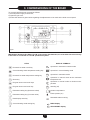
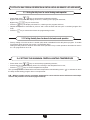
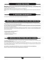
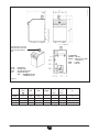
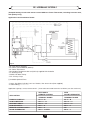
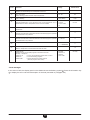
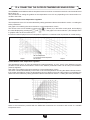
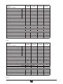
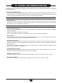
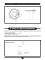
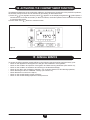
To be kept by the user
October 2010
Sirius FS
90-105-130-160
Floor Standing Condensing Gas Boilers
Installation, Operation & Maintenance Manual
Working towards
a cleaner future
heating specialists
Dear Customer,
We are sure your new boiler will comply with all your requirements.
Do not dispose of this booklet. This manual contains the information, which will help you to
run your boiler correctly and efficiently.
Do not leave any parts of the packaging (plastic bags, polystyrene, etc.) within children’s reach as they are a
potential source of danger.
potterton COMMERCIAL boilers bear the CE mark in compliance with the basic
requirements as laid down in the following Directives:
- Gas Directive 90/396/EEC
- Efficiency Directive 92/42/EEC
- Electromagnetic Compatibility Directive 2004/108/EEC
- Low Voltage Directive 2006/95/EC
ATTENTION
This boiler can only be installed and operate
in permanently, ventilated rooms in accordance with
BS6644
Instructions pertaining to the user
2
912.823.1 - GB
contents
instructions pertaining to the user
1. Instructions prior to installation
2. Instructions prior to commissioning
3. Commissioning of the boiler
4. Filling the boiler
5. Switching the boiler off
6. Prolonged standstill of the system. Frost protection 7. Servicing instructions and gas change
4
4
5
12
12
12
12
instructions pertaining to the installer
8. General information
9. Instructions prior to installation
10. Boiler installation and dimensions
11. Chimney flue connection
12. Connecting the mains supply
13. Adjusting the gas valves and gas change
14. Setting the boiler parameters
15. Control and operation devices
16. Positioning of the ignition and flame sensing electrode
17. Check of combustion parameters
18. Activating the chimney-sweep function
19. Annual service
20. Boiler schematic 21. Illustrated wiring diagram
22. Technical data
13
13
14
21
23
29
33
34
35
35
36
36
37
38-39
40
Instructions pertaining to the user
912.823.1 - GB
3
1. instructions prior to installation
This boiler is designed to heat water at a lower than boiling temperature at atmospheric pressure. The boiler must be
connected to a central heating system and/or to a domestic hot water supply system in compliance with its performances
and output power.
The boiler must be installed by a Qualified Service Engineer and ensure the following operations are carried out:
a)Check that the boiler is fit for operation with the type of gas available. For more details see the notice on the packaging
and the label on the appliance itself.
b)Careful checking that the flue terminal draft is appropriate; that the terminal is not obstructed and that no other appliance
exhaust gases are expelled through the same flue duct, unless the flue is especially designed to collect the exhaust gas
coming from more than one appliance, in conformity with the standards and regulations in force.
c) Careful checking that, in case the flue has been connected to pre-existing flue ducts, thorough cleaning has been carried
out in that residual combustion products may come off during operation of the boiler and obstruct the flue duct.
d) To ensure correct operation of the appliance and avoid invalidating the warranty, observe the following precautions:
1. Heating circuit
1.1.New system
Before proceeding with installation of the boiler, the system must be cleaned and flushed out thoroughly to eliminate
residual thread-cutting swarf, solder and solvents if any, using suitable proprietary products.
To avoid damaging metal, plastic and rubber parts, use only neutral cleaners, i.e. non-acid and non alkaline. The
recommended products for cleaning are:
SENTINEL X300 or X400 and FERNOX heating circuit restore. The use of this product must be strictly in accordance
with the maker’s directions. Finally the system must be dosed with a suitable inhibitor at 1% system volume.
1.2. Existing system
Before proceeding with installation of the boiler, the system must be cleaned and flushed out to remove sludge and
contaminants, using suitable proprietary products as described in section 1.1.
To avoid damaging metal, plastic and rubber parts, use only neutral cleaners, i.e. non-acid and non-alkaline such
us SENTINEL X100 and FERNOX heating circuit protective. To use this product proceed strictly in accordance with
the maker’s directions. Dose with inhibitor.
Remember that the presence of foreign matter in the heating system can adversely affect the operation of the boiler
(e.g. overheating and noisy operation of the heat exchanger).
Failure to observe the above will render the warranty null and void.
2. instructions prior to commissioning
Initial lighting of the boiler must be carried out by a qualified service engineer. Ensure the following operations are carried
out:
a) compliance of boiler parameters with (electricity, water, gas) supply systems settings.
b) compliance of installation with the standards and regulations in force.
c) appropriate connection to the power supply and earthing of the appliance.
Failure to observe the above will render the warranty null and void.
The instructions shall state the substance of the following:
This appliance is not intended for use by persons (including children) with reduced physical, sensory or mental
capabilities, or lack of experience and knowledge, unless they have been given supervision or instruction concerning use of the appliance by a person responsible for their safety.
Children should be supervised to ensure that they do not play with the appliance.
Instructions pertaining to the user
4
912.823.1 - GB
3. commissioning of the boiler
020503_1100
To correctly light the burner proceed as follows:
1) Provide power supply to the boiler;
2) Open the gas cock;
3) Follow the directions given below regarding the adjustments to be made at the boiler control panel.
Figure 1
IMPORTANT: Domestic Hot Water (D.H.W.) instructions discribed here, are to be taken into account only
if the boiler is connected to a D.H.W. production system.
KEYS
DISPLAY SYMBOLS
Domestic hot water on/off key
Operation in domestic hot water mode
Central heating water temperature setting key
Operation in central heating mode
Domestic hot water temperature setting key
Operation in automatic mode
Reset key
Operation in manual mode at the maximum
temperature set
Program access and scroll keys
Operation in manual mode at minimum temperature
Program access and scroll key
Standby (off)
Parameter setting key (decrease value)
Outdoor temperature
Flame present (on)
Parameter setting key (increase value)
Resettable alarm warning
Data display reset key
Central heating mode setting key
MAIN display
SECONDARY display
Instructions pertaining to the user
5
912.823.1 - GB
3.1 description of keys
(2) Central heating water temperature setting key. This key can be pressed to set the central heating
water output temperature as described in point 3-3.
.
(3) Domestic hot water temperature setting key. This key can be pressed to set the domestic hot
water temperature as described in point 3-4.
(10) Central heating mode operating key
The
key can be pressed to activate four boiler central heating operating modes; these modes are
identified by a black cursor line underneath the relative symbol on the display, and are as follows:
020503_0800
Dash
“Automatic mode”
active
Figure 2
•
•
•
•
Manual operation at the maximum temperature set. The boiler comes into operation regardless
of the timed program set. The operating temperature is that set using the
“Setting the maximum central heating temperature”);
key (point 3-3:
Manual operation at minimum temperature. The operating temperature is that set in point
3-6: “setting the minimum central heating temperature”.
Standby. The boiler does not work in central heating mode, although the antifreeze function is
still enabled.
(1) Domestic hot water on/off key: This key can be pressed to activate or deactivate this function,
which is identified on the display by a black cursor line under the symbol
.
(4) Reset key. In case of a fault, referred to in point 3-7 “Faults and resetting the boiler”, the boiler can
be restarted by pressing this key for at least two seconds (see 3-8).
If this key is pressed with no fault present, the display will show the message “E153”, and the same key
has to be pressed again (for at least two seconds) to restart the boiler.
(9) Data key. This key can be pressed repeatedly to display the following information:
- Temperature (°C) of the domestic hot water ( );
- outdoor temperature (°C) ( ); only provided with the outdoor temperature sensor probe connected.
Automatic operation. Operation of the boiler is controlled by the timed program as described
in point 3-5.1 “Daily timed program for operation of the central heating system”;
Press either of the
Instructions pertaining to the user
keys to return to the main menu.
6
912.823.1 - GB
3.2 setting the time
020503_0700
either of the
keys to access the programming function;
• Press
the display will show the letter P followed by a number (program line);
Figure 3
•Press the
the
•Press
•Press the
keys until the display shows P1, referring to the time to be set;
keys to set the time; on the display, the letter P will start to flash;
key to save and exit the programming function;
3.3 setting the maximum central heating temperature
- Press the
key (2-figure 1) to set the central heating water temperature;
- Press the
- Press either of the
keys to set the temperature required;
keys (1 or 10 - figure 1) to save and return to the main menu.
N.B – With the outdoor sensor connected, the
Press the
key (2 - figure 1) can be used to shift the central heating curve.
keys to decrease or increase the room temperature in the premises to be heated.
3.4 setting the maximum domestic hot water temperature
- Press the
key (3-figure 1) to set the maximum domestic hot water temperature;
- Press the
- Press either of the
keys to set the temperature required;
keys (1 or 10 - figure 1) to save and return to the main menu.
Instructions pertaining to the user
7
912.823.1 - GB
3.5 setting the daily program for operation in central heating and domestic hot water modes
3.5.1 Setting the daily times for central heating mode operation
- Press either of the
keys to access the programming function;
a) press these keys until the display shows P11, referring to the program start time;
b) press the
keys to set the time;
- Press the
key; the display will show P12, referring to the program end time;
- Repeat the operations described in points a and b until the third and last cycle is reached (program line
P16);
- Press the
key to save and exit from the programming function.
3.5.2 Setting the daily times for domestic hot water mode operation
- Factory setting of D.H.W. function is enable (ON) while is disabled D.H.W. daily times program. To enable
D.H.W. daily times program see section 14 (parameter H91).
Setting the daily times for domestic hot water mode operation-Carry out the operations described in section
3.5.1 for program lines 31 to 36.
3.6 setting the minimum central heating temperature
- Press either of the
keys to access the programming function;
- Press these keys until the display shows P5, referring to the temperature to be set;
- Press the
keys to set the temperature required.
This operating mode is enabled when minimum temperature central heating mode “
the daily central heating program does not require heat.
” is activated or when
N.b – With the outdoor sensor connected, parameter P5 can be used to set the minimum room temperature in the premises to be heated (night set-back).
Instructions pertaining to the user
8
912.823.1 - GB
3.7 table for user-settable parameters
Parameter Parameter description
N.
Factory
setting
Range
———-
0…23:59
25
25..80
P1
Time of day setting
P5
Minimum central heating temperature setting (°C)
P11
Start of first daily period of automatic central heating
6:00
00:00…24:00
P12
End of first daily period of automatic central heating
22:00
00:00…24:00
P13
Start of second daily period of automatic central heating
0:00
00:00…24:00
P14
End of second daily period of automatic central heating
0:00
00:00…24:00
P15
Start of third daily period of automatic heating
0:00
00:00…24:00
P16
End of third daily period of automatic central heating
0:00
00:00…24:00
Start of first daily period of domestic hot water production
0:00
00:00…24:00
End of first daily period of domestic hot water production
24:00
00:00…24:00
Start of second daily period of domestic hot water production
0:00
00:00…24:00
End of second daily period of domestic hot water production
0:00
00:00…24:00
Start of third daily period of domestic hot water production
0:00
00:00…24:00
Fine End of third daily period of domestic hot water production
0:00
00:00…24:00
0
0...1
* P31
* P32
* P33
* P34
* P35
* P36
P45
Reset of daily central heating and domestic hot water production programs (factory settings).
Press the - + keys together for about 3 seconds; the number 1 appears on the display.
Confirm by pressing either of the
keys
for program lines P31 to P36 are displayed only if Domestic Hot Water (D.H.W.) program (pa* Parameters
rameter H91 see section 14) is activated.
Instructions pertaining to the user
9
912.823.1 - GB
3.8 fault warnings and resetting the boiler
symbol (Figure 4).
020503_0500
If a fault occurs, a flashing warning code appears on the display.
The fault warnings appear on the main display (figure 1 a) together with the
To reset, press the reset
button for at least two seconds.
Figure 4
020503_0600
Fault warnings appear on the secondary display (figure 1 b) alternating with the time, both of them flashing
(figure 4.1). It is not possible to reset malfunction warnings which appear on the secondary display as the cause
of the alarm has first to be removed.
Figure 4.1
Instructions pertaining to the user
10
912.823.1 - GB
3.9 table of faults and error messages
Error
code
Description of fault
Corrective action
E10
Outdoor temperature sensor fault
Call an authorised service centre (*).
E20
ntc output sensor failure
Call an authorised service centre (*).
E50
Hot water ntc sensor failure
Call an authorised service centre (*).
E110
Safety or flue gas thermostat tripped
Press the reset key (for about 2 seconds: if this device is triggered repeatedly, call
the authorised service centre)
E128
Loss of flame during operation (the Call an authorised service centre.
ionization current has fallen below
the limit)
E129
Minimum fan speed limit not reached Call an authorised service centre.
E132
Gas pressure switch tripped / external Call an authorised service centre to check the gas pressure.
thermostat tripped
E133
No flame detected
Press the reset key (for about 2 seconds); if the fault persists, call the authorised
service centre to check polarity of ignition electrodes, ionisation current.
E151
Boiler circuit board error
If
symbol is displayed, press the reset
button otherwise switch off the
electricity supply to the boiler for at least 10 seconds; if the fault persists, call the
authorised service centre.
Check the positioning of the ignition and flame sensing electrode (see section 16).
E153
The reset key has been pressed Press the key again (about 2 seconds)
inappropriately
E154
Internal error on boiler circuit module Press and hold reset button (2 seconds approx.) then press again when warning
E153 appears
E160
Fan speed threshold not reached
Call an authorised service centre.
E164
Low water pressure
Check that the system is at the rated pressure. (Refer to the section on filling the
system). If the fault persists, call the authorised service centre.
(*) Auotoreset when fault disappears.
All the faults are displayed in order of importance; if several faults occur simultaneously, the first to be displayed
is the one with highest priority. After the cause of the first fault has been removed, the second one will be
displayed, and so on.
If any given fault occurs frequently, contact the authorised Service Centre.
Instructions pertaining to the user
11
912.823.1 - GB
4. filling the system
Important: Regularly check that the pressure displayed by the pressure gauge is 1 ÷ 4 bar when the central
heating system is cold. Open the boiler drain cock to reduce pressure if it is too high. Open the filling cock to
increase pressure if it is too low.
Always open the filling cock very slowly to allow any air to bleed off.
If the pressure in the system drops frequently, contact an authorised service centre to have the system checked.
5. switching the boiler off
To shut down the boiler switch off the electrical supply to the appliance.
6. prolonged standstill of the system. frost protection
We recommend you avoid draining the whole system as raw water makeup will lead to harmful limestone deposits inside the boiler and on the heating elements.
In case the boiler is not operated during wintertime and is therefore exposed to danger of frost we suggest you
add some specific-purpose anti-freeze to the water contained in the system (e.g.: propylene glycole coupled
with corrosion and scaling inhibitors).
The electronic management of the boilers includes a “frost protection” function in the central heating system
which operates the burner to reach a heating flow temperature of 30° C when the system heating flow temperature drops below 5°C.
The frost protection function is enabled if:
* electrical supply to the boiler is on;
* the gas service cock is open;
* the system pressure is as required;
* the boiler is not isolated.
7. servicing instructions and gas change
To maintain efficient and safe operation of your boiler have it checked by a Qualified Service Engineer at the
end of every heating season.
Careful servicing will ensure economical operation of the system.
Do not clean the outer casing of the appliance with abrasive, aggressive and/or easily flammable cleaners
(i.e.: gasoline, alcohol, and so on). Always isolate the electrical supply to the appliance before cleaning it (see
section 5 Turning off the boiler).
These boilers are produced for natural gas and can be converted to work with LPG (G 31).
Any gas change must be effected by a Qualified Service Engineer.
Instructions pertaining to the user
12
912.823.1 - GB
8. general information
The following remarks and instructions are addressed to Service Engineers to help them carry out a faultless
installation. Instructions regarding lighting and operation of the boiler are contained in the ‘Instructions pertaining to the user’ section.
Note that installation, maintenance and operation of the gas appliances must be performed exclusively by
qualified personnel in compliance with current standards.
Please note the following:
• Install the boiler in a permanent ventilated central heating boiler room.
• This boiler can be connected to any type of convector plates, radiators, thermoconvectors. Design the system
sections as usual though taking into account the available output / pump head performances, as shown in
chapter 10.4.
• Do not leave any packaging components (plastic bags, polystyrene, etc.) within children’s reach as they are
a potential source of danger.
• Initial lighting of the boiler must be effected by a Qualified Service Engineer.
• Make sure that the room where the boiler is installed has a sufficient supply of air to ensure complete combustion of the gas consumed by the appliance. Install unblockable ventilation grilles as necessary in accordance
with the Rules in force.
• Connect the boiler directly to an efficient flue to vent all fumes and combustion gases outdoors. Make sure
that the pipe connecting the boiler to the flue is not smaller in diameter than the boiler’s flue outlet. Make
sure that the flue is in good condition and free from holes or cracks that could reduce draw.
Failure to observe the above will render the warranty null and void.
9. instructions prior to installation
This boiler is designed to heat water at a lower than boiling temperature at atmospheric pressure. The boiler
must be connected to a central heating system and/or to a domestic hot water supply system in compliance
with its performances and output power.
IMPORTANT! The following components are not installed in the boiler as supplied. It is the installer’s
responsibility to provide them:
• Expansion vessel;
• Pressure safety valve;
• Circulation pump;
• Filling system cock.
Before connecting the boiler ensure the following operations have been completed:
a)Check that the boiler is fit for operation with the type of gas available. For more details see the notice on the
packaging and the label on the appliance itself.
b)Check that the flue terminal draft is appropriate; that the terminal is not obstructed and that no other appliance exhaust gases are expelled through the same flue duct, unless the flue is especially designed to collect
the exhaust gas coming from more than one appliance, in conformity with the standards and regulations in
force.
c)Check that, in case the flue has been connected to pre-existing flue ducts, thorough cleaning has been carried
out in that residual combustion products may come off during operation of the boiler and obstruct the flue
duct.
Instructions pertaining to the installer
13
912.823.1 - GB
To ensure correct operation of the appliance and avoid invalidating the warranty, observe the following
precautions:
1. Heating circuit
1.1.New system
Before proceeding with installation of the boiler, the system must be cleaned and flushed out thoroughly to
eliminate residual thread-cutting swarf, solder and solvents if any, using suitable proprietary products.
To avoid damaging metal, plastic and rubber parts, use only neutral cleaners, i.e. non-acid and non
alkaline. The recommended products for cleaning are:
SENTINEL X300 or X400 and FERNOX heating circuit restore. The use of this product must be strictly
in accordance with the maker’s directions. Finally the system must be dosed with a suitable inhibitor at
1% system volume.
1.2. Existing system
Before proceeding with installation of the boiler, the system must be cleaned and flushed out to remove
sludge and contaminants, using suitable proprietary products as described in section 1.1.
To avoid damaging metal, plastic and rubber parts, use only neutral cleaners, i.e. non-acid and nonalkaline such us SENTINEL X100 and FERNOX heating circuit protective. To use this product proceeding
strictly in accordance with the maker’s directions.
Remember that the presence of foreign matter in the heating system can adversely affect the operation
of the boiler (e.g. overheating and noisy operation of the heat exchanger). Dose with inhibitor.
Failure to observe the above will render the warranty null and void.
10. boiler installation and dimensions
Install the boiler in a position that ensures easy maintenance. You must be able to fully open the front access
door and have adequate access to the rear of the boiler.
If possible, install the boiler on a raised base of 200 mm in height to facilitate drainage of flue condensate.
When calculating the weight of the boiler on the floor, bear in mind the weight of the water in the heat exchanger
(see table 1).
Adjust the levelling feet to compensate for any unevenness in the floor.
Install the necessary utility connections starting from the water and gas connections on the rear of the boiler
(see table 1 for fitting type and size).
These appliances do not have any circulation pump, expansion tank or safety valve. These devices
must therefore be provided elsewhere in the system, and must be sized to suit the system’s thermal
capacity.
Connect the flue condensate drain pipe to a suitable water drain, ensuring an adequate slope.
To drain the boiler, use the drain tap at the rear.
Instructions pertaining to the installer
14
912.823.1 - GB
CT_0804 / 0906_2501
Insert the flue-gas union
and fasten the connector
to the flue-gas thermostat
CLEARANCE
FRONT= 700 mm
REAR = allow room to make
connections
SIDE = 10 mm
TOP = 500 mm
F CH: heating flow
R CH: heating return
GAS: gas inlet to the boiler
SC: condensate drain
SIZE = EXTERNAL 25 mm
INTERNAL 18 mm
Figure 5
Model
Depth
(mm)
Height
(mm)
Width
(mm)
Gas
fitting
A
Fitting
F
Fitting
R
(CH)
(CH)
Water contents
(l)
FS 90
801
850
450 G 3/4”
G 1 1/4’’
G 1 1/4’’
13,7
FS 105
871
850
450
G 1”
G 1 /2”
G 1 /2”
21
FS 130
1024
850
450
G 1”
G 1 /2”
G 1 /2”
23,3
FS 160
1132
850
450
G 1”
G 1 1/2”
G 1 1/2”
25,3
1
1
Table 1
Instructions pertaining to the installer
15
1
1
912.823.1 - GB
10.1 HYDRAULIC SYSTEM 1
(Pumped heating circuits with remote control QAA73 or Room Thermostat, including hot-water tank,
with primary loop)
CT_0664 / 0906_2202
Applications and Installation Details
Figure 6
- TS: Tank Sensor (QAZ36)*
- B3: Room Control Module (QAA73)*
- B1: Room Thermostat*
- B9: Outdoor Temperature Sensor (QAC34) supplied with the boiler
- P1: Heating Pump
- PDHW: Hot Water Pump
- PLP: Primary Pump
(*) Available Optional Extra
- Pumps, Hot Water Cylinder, Low Loss Header , Non return valve (Not supplied)
- Installer Wiring --------------Applications (pumps, sensor, remote control ...) have to be connected to terminal as follows (see also section 12):
WITH QAA73
REMOTE CONTROL
APPLICATION
TERMINAL BOARD
PRIMARY PUMP PLP
M1: A – B
DHW PUMP PDHW
M3: 13 – 14
HEATING PUMP P1
M3: 11 – 12
DHW SENSOR TS
M2: 7 – 8
REMOTE CONTROL QAA73
M2: 1 – 2
ROOM THERMOSTAT
M2: 3 – 4 OPEN
Instructions pertaining to the installer
16
WITH
ROOM THERMOSTAT
TERMINAL BOARD
M1: A – B
M3: 13 – 14
M3: 11 – 12
M2: 7 – 8
NO
M2: 3 – 4
912.823.1 - GB
Parameter changes requires (see also section 14):
PCB Description
Setting Parameter
PARAMETER
H552
H553
H615
H632
Hydraulic system
KonfigHKS
KonfigAusgang
WANFO Q8
H552 = 2 (*)
H553 = 21 (*)
H615 = 9 (*)
H632 = 00001100 (*)
(*) factory set
10.2 HYDRAULIC SYSTEM 2
(Pumped heating circuits with Room Thermostats and compensated circuit with remote control QAA73,
including hot-water tank, with primary loop)
Applications and Installation Details
- TS:Tank Sensor (QAZ36)*
- B3: Room Control Module (QAA73)*
- B1: Room Thermostat*
- B9: Outdoor Temp Sensor (QAC34) supplied with the boiler
- AGU2.500: Zone controller (Clip-in AGU2.500)*
- FS: Flow Sensor (QAD36: supplied with the AGU2.500)*
- P1: CTC Heating Pump
- P DHW: Hot Water pump
- PLP: Primary Pump
- 3WV: 3-Way Valve (power open / power close)
- P2: VTC Pump
(*) Available Optional Extra
CT_0663 / 0906_2203
- Pumps , Hot Water Cylinder, Low Loss Header, Non return valve (Not supplied)
- Installer Wiring --------------
Figure 7
Instructions pertaining to the installer
17
912.823.1 - GB
Applications (pumps, sensor, remote control ...) have to be connected to terminal as follows (see also section 12):
APPLICATION
PRIMARY PUMP PLP
DHW PUMP PDHW
HEATING PUMP P1
DHW SENSOR SB
REMOTE CONTROL QAA73 (LOW TEMPERATURE)
ROOM THERMOSTAT
HEATING PUMP P2
3 WAY VALVE 3WV
FLOW SENSOR FS
TERMINAL BOARD
M1: A – B
M3: 13 – 14
M3: 11 – 12
M2: 7 – 8
M2: 1 – 2
M2: 3 – 4
CLIP IN AGU 2.500
CLIP IN AGU 2.500
CLIP IN AGU 2.500
Parameter changes requires (see also section 14):
PCB PARAMETER
H552
H553
H615
H632
Description
Hydraulic system
KonfigHKS
KonfigAusgang
WANFO Q8
Setting Parameter
H552 = 50
H553 = 12
H615 = 9
00001111
10.3 HYDRAULIC SYSTEM 3
(Cascade with pumped heating circuits, Room Thermostats, primary loop)
Applications and Installation Details
- RT: Room Thermostat*
- B9: Outdoor Temperature Sensor (QAC34) supplied with the boiler
- OCI 420: Cascade interface controller (Clip-in OCI 420)*
- RVA 47: Cascade controller (RVA 47)*
- FS: Flow/return Sensor (QAD21)*
- P1: Heating Pump
- PLP: Primary Pump
(*) Available Optional Extra
- Pumps , Hot Water Cylinder, Low Loss Header, Non return valve (Not supplied)
- Installer Wiring --------------
Instructions pertaining to the installer
18
912.823.1 - GB
CT_0665 / 0906_2204
Figure 8
Applications (pumps, sensor, remote control ...) have to be connected to terminal as follows (see also section 12):
APPLICATION
PRIMARY PUMP PLP
HEATING PUMP P1
ROOM THERMOSTAT
FLOW/ RETURN SENSOR QAD 21
TERMINAL BOARD
M1: A – B
RVA 47
RVA 47
RVA 47
Parameter changes requires (see also section 14):
PCB PARAMETER
H552
H553
H615
H632
Description
Hydraulic system
KonfigHKS
KonfigAusgang
WANFO Q8
Setting Parameter
H552 = 80
H553 = 21
H615 = 9
00001111
If DHW circuit is required then DHW pump and DHW sensor have to be connected to terminal of RVA 47
Cascade Controller.
For more details refer to the instruction provided with the accessories RVA 47 and RVA 46 (compensated
circuit).
Instructions pertaining to the installer
19
912.823.1 - GB
Exchanger pressure drop (mH2O)
90
WATER FLOW RATE (l/h)
0512_1902
Exchanger pressure drop (mH2O)
130
FS 130 - 160
EXCHANGER
PRESSURE DROP.
160
WATER FLOW RATE (l/h)
Graph 1.1
FS 90 - 105
EXCHANGER
PRESSURE DROP.
105
Graph 1
0512_1901
10.4 EXCHANGERS PRESSURE DROP
BoilerHydraulic Resistance and Water Flow Rates
11°K ∆T
15°K ∆T 20°K ∆T kPa
Lit/sec
kPa
Lit/sec
kPa
Lit/sec
30°K ∆T
kPa
Lit/sec
FS 90
76,49
1,85
36,29
1,35
23,54
1,02
10,79
0,68
FS 105
74,53
2,17
40,21
1,59
22,56
1,19
12,75
0,80
FS 130
53,94
2,61
31,38
1,91
22,56
1,43
10,79
0,96
FS 160
49,03
3,26
31,38
2,39
19,61
1,79
10,79
1,19
Boiler
FS 90
Minimum Water Flow Rates
Lit/sec
0,52
FS 105
0,58
FS 130
0,72
FS 160
0,91
Instructions pertaining to the installer
20
912.823.1 - GB
11. chimney flue connection
Connect the boiler to the flue using a pipe made of stainless steel or plastic material with an internal diameter
of 100 mm, capable of resisting normal mechanical stresses over time, as well as high temperatures (<120°C)
and the chemical effects of fuel gases and their condensates. Insert the flue-gas union and fasten the
connector to the flue-gas thermostat before hooking up to the flue.
Whenever possible use a flue connection that can be disconnected for maintenance.
Important! Horizontal flue sections must have a minimum slope of 3° towards the boiler.
CT_0809 / 0902_2705
CT0667 / 0903_1601
Flue accessories made of plastic material for cascade or single installations are available.
Figure 7a
In case exhaust and intake flues not supplied by potterton COMMERCIAL have been installed, these must
be certified for the type of use and must have a maximum pressure drop in according to the values reported in
the table.
To ensure the correct rated heat input to the maximum and minimum heat input, it is necessary to update the speed (rpm)
of the fan, it depends on the lenght of the pipes, in accordance with the installation of flue and air pipes as indicated in
the tables below. The factory-set value is referred to the minimum length of flue pipe (0÷10 m). To carry such updating,
changing the speed of the fan at the (rpm and pwm%) , refer to par. 13-14.
Max. length of flue duct (L) : 20 m
Each 90° bend reduces the duct max. length by : 1 m
Each 45° bend reduces the duct max. length by : 0.5 m
flue pressure table available
Cascade solution
∆P available
flue duct B23 Ø 100
∆P available with
single non-return valve
Ø 110/110
∆P available with
double non-return valve
Ø 110/110
FS 90
110
110
-
FS 105
150
110
-
FS 130
170
-
80
FS 160
280
-
120
Instructions pertaining to the installer
21
912.823.1 - GB
11.2 Connector with C53 type
The kit is used to introduce combustion air from outside the installation area and comprises a hose to be
installed in the mixer body.
Please consult the instructions supplied with the kit.
CT_0813 / 0903_0601
For air ducts (diameter and length), see the kit manual.
Instructions pertaining to the installer
22
912.823.1 - GB
12. making the electrical connections
Electrical safety of the appliance is only guaranteed by correct earthing, in accordance with the current standards and regulations.
Connect the boiler to a 230V by means of the three-pin cable supplied with it make sure that the polarities are
correctly connected.
Use a double-pole switch with a contact separation of at least 3mm in both poles.
In case you replace the power supply cable fit a HAR H05 VV-F’ 3x0.75mm2 cable with an 8mm diameter
maximum outer sheath.
020523_0400
IMPORTANT: Check that the overall current drawn by accessories connected to the appliance is less
than 2 amp. If the value is greater, a relay must be wired between the boiler control circuit board and
the accessories drawing the higher current.
Terminal Block M1
Terminal Block M2
Cover
Cover
Figure 10
Facia panel
12.1 terminal blocks access
•
•
•
•
Isolate power to the boiler with the two-pole switch.
Remove the top facia panel cover (which is held by magnets).
Unscrew the two screws holding the facia panel in place.
Swing the facia panel forwards.
Main terminal block M1
• Remove the clip-on cover from terminal strip M1.
• The main terminal block incorporates a fast blow 3.15 A fuse (figure 10). Remove the black fuse holder to
check and/or replace the fuse.
Terminal block M2
• Unscrew the fixing screw and remove the cover from terminal block M2.
Terminal block M3
• Unscrew the fixing screws and remove the main cover.
Instructions pertaining to the installer
23
912.823.1 - GB
12.2 connecting the pumpS
Turn the control box downward to access terminal boards M1 and M3 used for the electrical connections by
removing the protective covers (see figure 11).
Terminals M1 a – b: connection of the Primary loop pump for the heating system (Plp)
Check the correct size and rating of the pump by referring to graph n° 1, which shows the boiler pressure
losses.
Terminals M3 11 – 12: connection for heating pump (P1)
Terminals M3 13 – 14: connection for hot water tank pump (PDHW)
The electrical specifications of the pump must be as follows:
230 V AC; 50 Hz; 1 A max; cos f > 0.8.
CG_1763 / 0906_2205
If the specifications of the installed pump are different, a relay must be wired between the boiler control circuit
board and the pump.
It is advisable not to adopt any electrical connection other than those described.
Connect earth to earth strip
Figure 11
12.3 Connecting the hot water tank sensor
Remove the resistor from terminals 9-10 of terminal strip M2 (figure 12), and connect the hot water priority
NTC sensor, which is supplied as an accessory.
The sensing element of the NTC device must be located in the recess provided on the storage tank (figure 12).
The temperature and on-off programming of the domestic hot water supply are selected directly from the
boiler control panel, as described in this manual under the user instruction headings.
Instructions pertaining to the installer
24
912.823.1 - GB
0602_0707/CG1764
safety
contact
room thermostat
0602_0708/CG1765
Figure 12
Figure 13
Instructions pertaining to the installer
25
912.823.1 - GB
12.4 description of the electrical connections to the boiler
Turn the control box downward to access terminal blocks M1 and M2 used for the electrical connections by
removing the two protective covers (see figure 10).
Terminals 1-2: connections for the optional SIEMENS QAA73 (optional extra) room temperature regulator.
These connections do not have any specific polarity.
Remove the bridge between terminals 1-2 “TA” on terminal block M1.
Read the instructions provided with the temperature regulator to ensure correct installation and programming.
Terminals 3-4: room temperature thermostat “TA”. Thermostats with integral accelerator resistor must not be
used. Check that there is no voltage across the ends of the two thermostat connection wires.
Terminals 5-6: external safety contact (commercially available device).
Terminals 7-8: connections for the optional SIEMENS QAC34 outdoor temperature sensor supplied with the
boiler. Read the instructions provided with the outdoor temperature sensor to ensure correct installation.
Terminals 9-10: connections for the optional domestic hot water priority sensor, for connecting single system
boilers to external DHW boilers.
CLIP-IN AGU 2.511
Terminals 3-4 L-N OUT: connection to signal lamp (230 V - 0,5 A max) for lockout alarm.
Terminals 5-6 L-N OUT: connection to signal lamp (230 V - 0,5 A max) for run mode.
For low voltage signal lamp remove the internal wiring and feed with an external low voltage power supply.
12.5 connecting the qaa73 room temperature regulator
The SIEMENS model QAA73 room temperature regulator, if required (optional accessory) must be connected
to terminals 1-2 of terminal block M2 in figure 12.
The link across terminals 3-4, provided for connection of a room temperature thermostat, must be removed.
The settings of the domestic hot water temperature and domestic hot water production schedule must be made
using this device.
The timed program of the central heating circuit must be set on the QAA73 if there is a single zone, or in relation
to the zone controlled by the QAA73 device.
The timed program for the central heating circuit of the other zones can be set directly on the boiler control
panel.
See the instructions provided with the QAA73 temperature regulator for the user parameter programming
procedure.
QAA73: parameters which can be set by the installer (service)
By pressing the two PROG buttons together for at least three seconds it is possible to access the list of parameters that the installer can display and/or set.
Press either of these buttons to change the parameter to display or change.
Press the [+] or [-] key to change the value displayed.
Press either of the PROG buttons again to save the change.
Press the information button (i) to quit programming.
Here follows a list of the most commonly used parameters:
Instructions pertaining to the installer
26
912.823.1 - GB
Parameter
Range
Default value
70
HC1 gradient heating curve
Selection of central heating circuit temperature curve “kt”
2.5…40
15
72
HC1 max. output
Central heating system maximum output temperature
25…85
85
74
Type of building
Light, Heavy
Light
75
Room compensation
Activation/deactivation of the influence of the room temperature. If it is
deactivated, the outdoor temperature sensor must be installed.
on HC1
on HC2
on HC1+HC2
nil
On HC1
77
Automatic adaptation of the temperature curve “kt” in relation to the room
temperature.
On - off
78
Opt Start Max
Maximum time the boiler is switched on ahead of the timed program to optimise
the temperature in the premises.
0…360 min
0
79
Opt Stop Max
Maximum time the boiler is switched off ahead of the timed program to optimise
the temperature in the premises.
0…360 min
0
80
HC2 gradient heating curve
2.5…40
—.- = not active
—.-
90
DHW Red Setp
Minimum temperature of the domestic domestic hot water
DHW program
Selection of the type of timed program for domestic hot water.
24 h/day = always on
PROG HC-1h
= as HC1 central heating program less one hour
PROG HC
= as central heating program
PROG DHW
= specific domestic hot water program
(see also program lines 30-36)
10…58
10
Line no.
91
24 h/day
TSP HC-1h
TSP HC
TSP DHW
On
24 h/day
- Fault messages
In the event of fault, the display panel on the QAA73 shows the flashing symbol . Press the information key
( ) to display the error code and a description of the fault (see table on paragraph 3.9).
Instructions pertaining to the installer
27
912.823.1 - GB
12.6 connecting the outdoor temperature sensor probe
The SIEMENS model QAC34 outdoor temperature sensor must be connected to terminals 7-8 of terminal board
M2 in figure 12.
The procedures for setting the gradient of the temperature curve “kt” vary depending on the accessories connected to the boiler.
a) Without QAA73 room temperature regulator:
The temperature curve “kt” must be selected by setting parameter H532 as described in section 14 “setting the
boiler parameters”.
See graph 2 for selecting the curve referred to a room temperature of 20°C.
The chosen curve can be shifted by pressing the
(2), button (2) on the boiler control panel, and modifying
020523_0600
the value displayed by pressing the
and
. keys. See graph 3 for curve selection. (The example show
in graph 3 refers to the curve Kt=15).
Increase the value displayed if the room temperature required is not reached inside the premises for central heating.
Graph 2
TM = Flow temperature
Te = Composite outside temperature
Sth = Kt Curve
Graph 3
b) With QAA73 room temperature regulator:
020523_1000
The temperature curve “kt” must be selected by setting parameter 70 “HC1 curve” of the QAA73 room temperature control device as described in section 12.4 “QAA73: parameters which can be set by the installation
(service) engineer”.
See graph 4 for selecting the curve referred to a room temperature of 20°C.
The curve is shifted automatically on the basis of the room temperature set using the QAA73 climate control.
If the system is divided into zones, the temperature curve “kt” relating to the part of the system not controlled by the
QAA73 must be selected by setting parameter H532 as described in section 14 “setting the boiler parameters”.
Graph 4
TM = Flow temperature
Te = Composite outside temperature
c) With AGU2.500 for control of a low temperature system:
Refer to the instructions provided with the AGU2.500 accessories for connection and control of a variable
temperature zone.
Instructions pertaining to the installer
28
912.823.1 - GB
13. adjusting the gas valves
FS 90 - 105 models have a single gas valve (figure 14 a).
FS 130 - 160 models have a double gas valve (figure 14 b).
0502_2108
Gas nozzle
Figure 14a
LEGEND:
Pi:
Gas supply pressure
connection point
P out: Pressure connection point for
measurement of the OFFSET
Pl:
Air signal input from fan
V:
Gas flow adjuster screw (high)
K:
OFFSET adjuster screw (low)
0502_2109
Gas nozzle
Figure 14b
Instructions pertaining to the installer
29
912.823.1 - GB
13.1 SINGLE GAS VALVE MODELS (FS 90 - 105) figurE 14a
Proceed as follows to adjust the single gas valve:
• Insert the flue analysis probe into the flue sampling hole as instructed in section 17 (figure 17).
• Press and hold the
and
keys on the control panel simultaneously for 7 seconds until the symbols
appear on the display in the position shown in figures 15a and 15b
. You are now in ‘calibration
mode’.
• Press the
key to set the maximum heat output, with the display showing 100% (figure 15a).
Caution: in the event of the boiler failing to ignite, or when replacing the gas valve, the recommended
procedure is to tighten the adjuster screw (V) fully and then back off 3 turns, repeating the steps
described above.
• Turn the adjuster screw V on the gas valve until you achieve the CO2 levels shown in table 2.1 for natural
gas (G20) and in table 2.2 for propane (LPG):
-
-
Turn the screw anti-clockwise to increase the CO2 level.
Turn the screw clockwise to decrease the CO2 level.
• Press the
key to set the minimum heat output, with the display showing 0% (figure 13b).
• Turn the adjuster screw K on the gas valve until you achieve the CO2 levels shown in table 2:
-
-
Turn the screw clockwise to increase the CO2 level.
Turn the screw anti-clockwise to decrease the CO2 level.
13.2 double gas valve models (FS 130 - 160) figure 14b
Proceed as follows to adjust the double gas valve:
• Connect a pressure gauge to the P1OUT pressure measurement hole on valve 1.
• Insert the probe of the flue gas analyzer in the sampling port as indicated in heading 17 - figure 17.
• Switch on the boiler, activating the “setting function” from the control panel by pressing and holding the
and
keys simultaneously until the symbols are displayed, positioned as illustrated in figures
15a and 15b
. You are now in ‘calibration mode’.
• Press the
key to set the maximum heat output, with the display showing 100% (figure 15a).
Caution: in the event of the boiler failing to ignite, or when replacing the gas valves, the recommended
procedure is to tighten the adjuster screws (V1) and (V2) fully and then, depending on the model, back
off 2¼ turns (FS 130) or 2½ turns (FS 160), repeating the steps described above.
• Turn both gas valve adjuster screws (V1) and (V2) so as to set the CO2 values as indicated in table 2.1 for
natural gas (G20) and in table 2.2 for propane (LPG):
-
-
Turn the screw clockwise to decrease the CO2 level.
Turn the screw anti-clockwise to increase the CO2 level.
• Press the
key to set the minimum heat output, with the display showing 0% (figure 15b).
• Turn the adjuster screw K1 of gas valve 1 so as to set the pressure value (Pout) as indicated in table 2.1
for natural gas (G20) and in table 2.2 for propane (LPG):
c.
Turn the screw clockwise to increase pressure (CO2 increasing).
Instructions pertaining to the installer
30
912.823.1 - GB
d.
Turn the screw anti-clockwise to decrease pressure (CO2 decreasing).
• Remove the pressure gauge from the P1OUT port and connect to the P2OUT port of gas valve 2.
• Turn the adjuster screw K2 of gas valve 2 so as to set the pressure value (Pout) as indicated in table 2.1
for natural gas (G20) and in table 2.2 for propane (LPG):
Figure 15a
⇑
0502_2110
0307_2201
• Check that the CO2 value at minimum heat output is as indicated in table 2.1 or 2.2. The value can be
optimized by making the necessary fine adjustment to screw K2.
Figure 15b
⇑
13.3 gas conversion
IMPORTANT: in the event of converting the boiler from natural gas (G20) to propane (LPG), the following
operation must be carried out before proceeding to adjust the gas valve as described above:
• For models with one valve, replace the diaphragm on the gas valve outlet (figure 14a).
To replace the diaphragm, disassemble the gas valve by undoing the inlet and outlet fittings, then unscrew
the nozzle with a pair of straight round nose pliers.
Check the fluid-tightness of the gas fittings removed previously.
• For models with two gas valves, replace the diaphragm located at the venturi inlet (figure 14b).
To enable this operation, the gas valve manifold must first be removed.
Check the fluid-tightness of the gas fittings removed previously.
• Set parameters H536 - H541 - H608 - H609 - H610 - H611 - H612 - H613 by way of the display on the
control panel.
The values to be set are given in tables 2.1 and 2.2. The programming methods are described in chapter 14.
Instructions pertaining to the installer
31
912.823.1 - GB
Gas consumption at 15 °C
1013 mbar
Gas G20 - 2H - 20 mbar
FS 90
FS 105
FS 130
FS 160
MJ/m3
34,02
34,02
34,02
34,02
Consumption at max. heat output
3
m /h
9,26
10,9
13,08
16,35
Consumption at min. heat output
m3/h
3,50
3,89
4,23
4,39
Gas nozzle
mm
11,5
12
11
11,5
%
8,7
8,7
8,7
8,7
CO2 min. heat output
%
8,6
8,6
8,4
8,4
Pout pressure at minimum power
Pa
-
-
-4
-5
Parameters H536-H613 (rpm) at maximum power
5100
5650
4650
6000
Parameters H541-H610 (pwm %) at maximum power
90
100
55
100
Parameter H612 (rpm) at minimum power
1900
2100
1600
1550
Parameter H609 (pwm) at minimum power
15
15
10
9,5
3600
3600
2600
2900
15
15
20
20
PCI (NET)
CO2 max. heat output
Parameter H611 (rpm) ignition load
Length of exhaust flue : 0 ÷ 10 m
Parameter H608 (pwm) ignition load
30
30
Length of exhaust flue : 10 ÷ 20 m
Parameter H608 (pwm) ignition load
40
40
Cascade solution with single non-return valve Ø 110/110
Parameters H536-H613 (rpm) at maximum power
5500
6000
-
-
Parameter H612 (rpm) at minimum power
2200
2250
-
-
Parameter H609 (pwm) at minimum power
16,5
16
40
40
FS 90
FS 105
FS 130
FS 160
MJ/Kg
46,34
46,34
46,34
46,34
Consumption at max. heat output
Kg/h
6,77
7,97
9,56
11,95
Consumption at min. heat output
Kg/h
2,57
2,86
3,10
3,22
Gas nozzle
mm
7,8
7,8
7,8
7,8
%
10,2
10,2
10,2
10,2
CO2 min. heat output
%
9,3
9,8
10,2
10,2
Pout pressure at minimum power
Pa
-
-
-7
-8
Parameters H536-H613 (rpm) at maximum power
4600
5150
4300
5350
Parameters H541-H610 (pwm %) at maximum power
90
100
55
100
Parameter H612 (rpm) at minimum power
1900
1950
1450
1450
Parameter H609 (pwm) at minimum power
14,5
14,5
10
9,5
4200
4200
2600
2900
15
15
20
20
Parameter H608 (pwm) ignition load
Table 2.1
Gas consumption at 15 °C
1013 mbar
Gas G31 - 3P - 37 mbar
PCI (NET)
CO2 max. heat output
Parameter H611 (rpm) ignition load
Length of exhaust flue : 0 ÷ 10 m
Parameter H608 (pwm) ignition load
40
40
Length of exhaust flue : 10 ÷ 20 m
Parameter H608 (pwm) ignition load
50
50
Cascade solution with single non-return valve Ø 110/110
Parameters H536-H613 (rpm) at maximum power
5000
5500
-
-
Parameter H612 (rpm) at minimum power
2200
2100
-
-
Parameter H609 (pwm) at minimum power
16,5
15
-
-
50
50
-
-
Parameter H608 (pwm) ignition load
Table 2.2
Instructions pertaining to the installer
32
912.823.1 - GB
14. setting the boiler parameters
The boiler parameters may only be modified by professionally qualified staff proceeding as follows:
a) Press the
, keys on the boiler’s front panel together for about 3 s until the parameter H90 appears on the display;
b) Press the
keys to select the parameter for modification;
The boiler parameters may only be modified by professionally qualified staff proceeding as follows:
a) Press the
b) Press the
c) Press the
d) Press the
, keys on the boiler’s front panel together for about 3 s until the parameter H90 appears on the display;
keys to select the parameter for modification;
and keys to modify the parameter;
key to exit the programming function.
The following are the parameters generally used:
Parameter
N.
Factory setting
Description
H90
Minimum D.H.W. temperature setting (°C).
10
H91
D.H.W. activation program
(0=active; 1=not active)
1
H505
Maximum temperature (°C) of the central heating circuit HC1 corresponding to:
- the main circuit in systems with just one zone;
- the circuit of the zone where the QAA73 room temperature control device is installed in case
of systems with more than one high-temperature zone;
- the high temperature zone circuit in mixed systems and if the SIEMENS AGU2.500 accessory
is used.
80
H507
Maximum temperature (°C) of the central heating circuit HC2 of a system with more than one
zone, corresponding to the circuit of the low-temperature zone if the SIEMENS AGU2.500
accessory is used.
80
H516
Automatic Summer / Winter switching temperature (°C).
20
H532
Selection of temperature curve of central heating circuit HC1 (see Graph 2)
15
H533
Selection of temperature curve of central heating circuit HC2 (see Graph 2)
15
H608
PWM (%) Setting: Ignition load
H611
Speed setting (rpm) : Ignition load
H609
PWM Setting (%) : minimum power
H541-H610
H612
H536-H613
PWM Setting (%) : maximum power Central heating / Domestic hot water
See table 2
Speed setting (rpm) : minimum power
Speed setting (rpm) : maximum power Central heating / Domestic hot water
H544
Pump post-circulation time in central heating mode (min)
10
H545
Burner operating pause time between two start-ups (s)
180
H552
(*)
Hydraulic system setting (see instructions provided with the SIEMENS AGU2.500 accessory)
H552 = 50 with AGU2.500 and QAA73
H552 = 80 with RVA 47
2
H553
(*)
Configuration of heating circuits
H553 = 12 with AGU2.500
21
H615
Programmable function:
9
H632
(*)
Heat demand to be supported by the system pump
H632 = 00001111 with AGU2.500 and RVA 47
H641
Fan overrun time setting (s)
10
H657
Setpoint of autonomous ANTILEGIONELLA function
60...80 °C = setting temperature range
0 = function inactive
0
00001100
Table 3
( * ) For these parameters see section 10.1 - 10.2 - 10.3 (hydraulic system).
If the electronic circuit board is replaced, make sure that the parameters set are those specific to the boiler
model, as indicated in the documentation available from the authorised Service Centre.
Instructions pertaining to the installer
33
912.823.1 - GB
15. control and operation devices
The boiler has been designed in full compliance with European reference standards and in particular is equipped
with the following:
• Overheat safety thermostat
This thermostat interrupts the gas flow to the main burner in case the water contained in the circuit has overheated. Under these conditions the boiler locks out and can only repeat the ignition procedure by pressing
of the reset button on the boiler after the cause of the trip has been rectified.
It is strictly forbidden to disable this safety device.
• Flue thermostat
This device, positioned on the flue inside the boiler, interrupts the flow of gas to the burner if the temperature
exceeds 90 °C. After verifying the cause of the trip, press the reset button positioned on the thermostat
itself, then press the reset button on the boiler.
It is forbidden to disenable this safety device
• Flame ionization detector
The flame sensing electrode guarantees safety of operation in case of gas failure or incomplete interlighting
of the main burner.
Under such conditions the boiler is locked out.
You must press the reset button on the boiler to restore the normal operating conditions.
• Pump overrun
The electronic control system keeps the pump operating for 10 minutes in central heating mode after the
room temperature thermostat has switched off the main burner.
• Frost protection device
The boilers electronic management includes a “frost protection” function in the central heating system which
operates the burner to reach a heating flow temperature of 30°C when the system heating flow temperature
drops below 5 °C.
This function is enabled as long as the boiler is connected to the a.c. power supply gas supplies and the
pressure in the system is as specified.
• Pump-blocking prevention
In case there is no call for heat either from the central heating system or from the DHW system for 24 hours
continous the pump will automatically switch on for 10 seconds.
• Hydraulic pressure sensor
This device enables the main burner only to be switched on if the system pressure is over 0.5 bar.
• Gas pressure switch
This device enables the burner only to be switched on if the gas pressure is over 12 mbar.
Instructions pertaining to the installer
34
912.823.1 - GB
0503_2204
16. positioning of the ignition and flame sensing electrode
Figure 16
17. check of combustion parameters
0811_1703 / CT_0782
Drill a hole in the flue at a distance from the boiler equivalent to twice the diameter of the flue to measure
combustion efficiency and combustion flue composition in accordance with the rules in force. Use this hole to
measure the following parameters:
• Combustion flue temperature
• Oxygen (O2) or carbon dioxide (CO2) concentration.
• Carbon monoxide (CO) concentration.
Measure the temperature of combustion air near the air inlet to the boiler. The necessary hole must be made by
the technician responsible for the heating system when the system is first started up, and must then be closed
to ensure that the flue remains properly sealed during normal operation.
Important! Close the flue test point
hole on completion of measurements.
boiler flue test
point hole
Figure 17
Instructions pertaining to the installer
35
912.823.1 - GB
18. activating the chimney sweep function
020429_0200
To facilitate measurement of the combustion efficiency and improve the cleanliness of the production products,
the chimney sweep function can be activated by proceeding as described below:
1)Press the
(2-3) together until the pointer “ ” appears on the display alongside the symbol (about 3
seconds but no more than 6 seconds). In these conditions, the boiler operates at the maximum heat output
in central heating mode.
2) Press either of the
buttons to exit the function
Figure 18
19. annual service
To ensure the boiler operates at peak efficiency, the following checks must be performed every year:
• Check on the appearance and tightness of the gas and combustion circuit gaskets;
• Check on the condition and position of the ignition and flame sensing electrodes (see section 16);
• Check on the condition of the burner and its fixing to the aluminium flange;
• Check for any dirt in the combustion chamber. Use a vacuum-cleaner for this cleaning operation;
• Check that the gas valve is calibrated correctly (see section 13);
• Check that there is no dirt in the siphon;
• Check on the central heating system pressure;
• Check on the central heating expansion vessel pressure.
Instructions pertaining to the installer
36
912.823.1 - GB
CT_0818 / 0907_0101
20. boiler schematic
Figure 19
Key:
1 Water pressure gauge
2 Siphon (condensate)
3 Central heating ntc sensor
4 105°C overheat safety thermostat
5 Gas valve
6 Heat exchanger
7 Flame detector electrode (ionisation probe)
8 Burner
9 Ignition electrode
10 Mixer with venturi
11 Gas injector
12 Fan
13 Flue joint
14 Automatic air vent
15 Hydraulic pressure sensor
16 Boiler drain point
17 Joint flue with flue thermostat
18 Flue thermostat
19 Gas pressure switch
20 Seat of air intake pipe
Instructions pertaining to the installer
37
912.823.1 - GB
21. illustrated wiring diagram
CT_0660 / 0907_0102
21.1 fs 90 - 105
Instructions pertaining to the installer
38
912.823.1 - GB
CT_0661 / 0907_0103
21.2 FS 130 - 160
Instructions pertaining to the installer
39
912.823.1 - GB
22. technical data
Boiler model FS
Category
Maximum heat input (net/gross)
kW
Minimum heat input (net/gross)
kW
Maximum heat output 75/60°C
kW
kcal/h
Maximum heat output 50/30°C
kW
kcal/h
Minimum heat output 75/60°C
kW
kcal/h
Minimum heat output 50/30°C
kW
kcal/h
Useful efficiency according to 92/42/CEE directive —
Central heating system max. pressure
bar
90
II2H3P
87,2-96,7
33,1-36,7
85
73100
91,6
78776
32,2
27692
34,9
30014
★★★★
4
105
130
160
II2H3P
II2H3P
II2H3P
102,7-113,8 123,2-136,6 154-170,7
36,8-40,8
40-44,3
41,5-46,02
100
120
150
86000
103200
129000
107,8
129,7
162
92708
111542
139320
35,8
39
40,4
30788
33540
34744
38,8
42,1
43,7
33368
36206
37582
★★★★
★★★★
★★★★
4
4
4
Heating circuit temperature range °C
25÷80
25÷80
25÷80
25÷80
Flue type
—
B23 - B23P - C53*
Flue duct diameter
mm
100
100
100
100
Max. flue mass flow rate
kg/s
0,041
0,049
0,058
0,073
Min. flue mass flow rate
kg/s
0,016
0,018
0,019
0,020
Max. flue temperature
°C
78
80
77
75
NOx class —
5
5
5
5
Type of gas used
—
G20
G20
G20
G20
—
G31
G31
G31
G31
Natural gas feeding pressure 2H
mbar
20
20
20
20
Propane gas feeding pressure 3P
mbar
37
37
37
37
Gas Consumption (NG)
m3/hr
9,26
10,9
13,8
16,35
Minimum Operating Pressure
Bar
1
1
1
1
High Level Ventilation to BS6644 boiler room
cm2 174,4
205,4
246,4
308
Low Level Ventilation to BS6644 boiler room
cm2 348,8
410,8
492,8
616
Mechanical inlet to BS6644
m3/sec
0,067
0,08
0,1
0,12
Water Flow at 20°K Δt
lit/sec
1,02
1,19
1,44
1,80
Hydraulic Resistance at 20°K Δt
kPa 25
25
22
21
Cold Feed Size to BS6644
mm 25
25
25
32
Safety valve size to BS6644 (open vent)
mm
19
19
19
19
Open vent BS6644
mm
32
32
32
32
Maximum Flow Temperature
°C 85
85
85
85
Water Content
lit 13,7
21
23,3
25,3
Power supply voltage
V
230
230
230
230
Power supply frequency
Hz
50
50
50
50
Rated power supply
W
100
160
135
235
Net weight
Dimensions
height
width
depth
kg
mm
mm
mm
75
850
450
801
83
850
450
871
95
850
450
1014
103
850
450
1132
* C53 (only with air intake kit)
Instructions pertaining to the installer
40
912.823.1 - GB
Instructions pertaining to the installer
41
912.823.1 - GB
Instructions pertaining to the installer
42
912.823.1 - GB
Instructions pertaining to the installer
43
912.823.1 - GB
Commercial sales
technical & service enquiries
Tel:
Fax:
Sales hotline:
Technical helpline:
Service hotline:
e-mail:
web:
Applications & Installations
0845 070 1055
0845 070 1059
0845 070 1056
0845 070 1057
0845 070 1058
[email protected]
www.pottertoncommercial.co.uk
Our experienced technical support team are available to offer
advice on any aspect of heating system design and boiler
installation.
Please contact:
0845 070 1057
Commercial service offices
Our service organisation covers the whole of the UK to look after
your needs for all Potterton Commercial products.
Our service office offers a wide range of specialised services
including:
Spares
Potterton Commercial spares are available nationwide
through the interpart network of approved stockists.
Alternatively please contact:-
•
•
•
•
•
•
•
Interpart
Brooks House
Coventry Road
Warwick CV34 4LL
Tel: 0844 871 1540
Burner commissioning for all fuels
Boiler service contracts
Breakdown and repair services
Burner and boiler replacement
Oil/gas conversions
Water treatment and descaling
Packaged units
All descriptions and illustrations contained within this leaflet have
been carefully prepared, but we reserve the right to make
changes and improvements in our products which may affect
the accuracy of the information in this leaflet.
Baxi Commercial Division
Wood Lane, Erdington,
Birmingham B24 9QP
Email: [email protected]
www.pottertoncommercial.co.uk
Sales:
0845 070 1056
Technical:
0845 070 1057
heating specialists