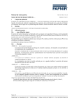
1
Technische Dokumentation TORRIX-HART The magnetostrictive level sensor with HART Protocol Edition: 10/2010 Version: 5 Article no.: 207095 FAFNIR GmbH Bahrenfelder Str. 19 22765 Hamburg Tel: +49 /40 / 39 82 07-0 Fax: +49 /40 / 390 63 39 Table of contents 1 Introduction .....................................................................................................4 2 Properties.........................................................................................................5 3 Device Identification .......................................................................................6 4 HART Commands.............................................................................................7 4.1 4.2 4.3 Universal Commands ..................................................................................................... 7 Common Practice Commands........................................................................................ 8 Device Specific Commands .......................................................................................... 10 5 Device Variables ............................................................................................11 5.1 5.2 5.3 Device Variable 0, Level of Float 1 ................................................................................ 11 Device Variable 1, Level of Float 2 ................................................................................ 11 Device Variable 3, Interface Layer Thickness ................................................................. 12 6 Dynamic Variables .........................................................................................12 6.1 Mapping of the Dynamic Variables .............................................................................. 12 7 Status Information ........................................................................................13 7.1 7.2 7.3 7.4 Field Device Status ....................................................................................................... 13 Extended Device Status ................................................................................................ 13 Additional Device Status .............................................................................................. 13 Device Specific Status Bits ............................................................................................ 14 8 Analogue Output ..........................................................................................15 9 Performance...................................................................................................16 9.1 9.2 9.3 9.4 9.5 9.6 9.7 9.8 Power-Up .................................................................................................................... 16 Device Reset ................................................................................................................ 16 Self Test....................................................................................................................... 17 Sampling Rate ............................................................................................................. 17 Command Response Delay .......................................................................................... 17 Non-Volatile Memory................................................................................................... 18 Write Protection .......................................................................................................... 18 Damping ..................................................................................................................... 18 10 HART recommendations ...............................................................................19 10.1 10.2 Wiring and installation ................................................................................................. 19 Devices on a HART network ......................................................................................... 19 11 Configurations using the HART protocol.....................................................20 11.1 11.2 11.3 FAFNIR HART-Setup ..................................................................................................... 20 Emerson 375 Field Communicator ............................................................................... 22 Smar CONF401............................................................................................................ 22 Page 2/27 TORRIX with HART protocol 11.4 11.5 Siemens PDM............................................................................................................... 22 FDT/DTM based configuration tools.............................................................................. 23 12 Configurations using the Local Panel...........................................................23 13 Tables..............................................................................................................24 13.1 13.2 Unit Conversion ........................................................................................................... 24 Damping Values........................................................................................................... 24 14 Annexes .........................................................................................................25 14.1 14.2 Annex A. Capability Checklist....................................................................................... 25 Annex B. Default Configuration ................................................................................... 26 © Copyright: Reproduction and translation only with the written consent of the FAFNIR company. FAFNIR reserves the right to make product modifications without prior notice. HART® is a registered trademark of the HART Communication Foundation. TORRIX with HART protocol Page 3/27 1 Introduction This specification is designed to complement other TORRIX documents (e.g. TORRIX Technical Documentation). It provides a complete description of the TORRIX Field Device from a HART Communication point of view. The FAFNIR GmbH magnetostrictive sensor TORRIX complies with the HART Protocol Revision 6. This document describes all the device specific features and documents HART Protocol implementation details. The functionality of the TORRIX is described in a way that allows its proper application in a process and its complete support in HART capable Host Devices. This document assumes the reader is familiar with HART Protocol requirements and terminology. The safety instructions in this manual are labelled as follows: If you do not observe these safety instructions, there is a risk of accidents or the sensor could be damaged. Useful information which ensures proper functioning of the system and facilitates your work. Page 4/27 TORRIX with HART protocol 2 Properties The high-precision and robust TORRIX level sensor is designed to provide continuous gauging of liquid media levels in tanks. The measuring principle used by the sensor exploits the physical effect of magnetostriction and is largely unaffected by temperature. Magnetostriction is particularly ideal where level measurements are required to be extremely accurate, e.g. in the chemical industry. The level sensor outputs measuring signals in the range 4 to 20 mA. Available in lengths of 200 to 6,000 mm, it is compatible with a variety of tank dimensions. It also comes in the following versions: Version for installation on a bypass with magnetic float Version with flange Version with screw-in unit for infinitely variable positioning of the level sensor The Ex-approved version of the level sensor can be installed in potentially explosive atmospheres in which electrical equipment of category 1 (zone 0) or category 1/2 (zone 0/1) are required. In the HART variant TORRIX can be ordered with 2 floats instead of 1 float. This allows to measure 3 different process values with only one sensor. In a tank with two liquids it is possible to read out the total level, the interface level and also the interface layer thickness via the HART protocol. TORRIX with HART protocol Page 5/27 3 Device Identification Fig. 1: Picture of the Level Sensor TORRIX The name plate is located on the TORRIX probe head. Manufacturer Name FAFNIR GmbH Manufacturer ID Code 198 (C6 Hex) Model Name TORRIX Device Type Code 128 (80 Hex) Device Revision 3 HART Protocol Revision 6 Number Of Device Variables 1 to 3 Physical Layers Supported FSK Physical Device Category 2-wire transmitter Table 1: Device Identification Page 6/27 TORRIX with HART protocol 4 HART Commands 4.1 Universal Commands All HART Rev. 6 Universal Commands are supported. CMD Id Function 0 Read Unique Identifier 1 Read Primary Variable 2 Read Loop Current And Percent Of Range 3 Read Dynamic Variables And Loop Current 6 Write Polling Address 7 Read Loop Configuration 8 Read Dynamic Variable Classification 9 Read Device Variable With Status 11 Read Unique Identifier Associated With Tag 12 Read Message 13 Read Tag, Descriptor, Date 14 Read Primary Variable Transducer Information 15 Read Device Information 16 Read Final Assembly Number 17 Write Message 18 Write Tag, Descriptor, Date 19 Write Final Assembly Number 20 Read Long Tag 21 Read Unique Identifier Associated With Long Tag 22 Write Long Tag Command #3 (Read Dynamic Variables And Loop Current) The answer to Command #3 does always contain four Dynamic Variables (PV,SV,TV,QV). Command #18 (Write Tag, Descriptor, Date) Invalid date codes received within the Command #18 will result in not executing the command and returning Error Code #9 (Invalid Date Code Detected) instead. Command #14 (Read Primary Variable Transducer Information) The Transducer Serial Number returned within the answer to Command #14 is set to zero by default. TORRIX with HART protocol Page 7/27 4.2 Common Practice Commands The following Common Practice Commands are supported. CMD Id Function 33 Read Device Variables 34 Write Primary Variable Damping Value 35 Write Primary Variable Range Value 36 Set Primary Variable Upper Range Value 37 Set Primary Variable Lower Range Value 38 Reset Configuration Changed Flag 40 Enter/Exit Fixed Current Mode 41 Perform Self Test 42 Perform Device Reset 44 Write Primary Variable Units 45 Trim Loop Current Zero 46 Trim Loop Current Gain 48 Read Additional Device Status 49 Write Primary Variable Transducer Serial Number 50 Read Dynamic Variable Assignments 51 Write Dynamic Variable Assignments 53 Write Device Variable Units 54 Read Device Variable Information 55 Write Device Variable Damping Value 59 Write Number Of Response Preambles 71 Lock Device 72 Squawk 73 Find Device 76 Read Lock Device State Command #42 (Perform Device Reset) After Command #42 is used to perform a device reset it takes about 2 seconds before the transmitter is ready to answer the next command. Command #48 (Read Additional Device Status) The answer to Command #48 does contain 8 response data bytes. See Section 7.3 for information on the individual status bits. Page 8/27 TORRIX with HART protocol Command #72 (Squawk) The device will flash the LED of the Local Panel (only visible after removing the transmitter head cover) for about 5 seconds after Command #72 has been received. While the LED is flashing the loop current is set to 12 mA and the Output Current Fixed bit in the Response Code will be set. Death or serious injury could result from using Command #72 when the transmitter is used for process control at that time. So be sure that the transmitters analogue output is not used for process control when using Command #72. Command #73 (Find Device) The device will only answer Command #73 when it has been armed before. To arm the device the two buttons of the Local Panel (only reachable after the transmitter head cover has been removed) have to be pressed simultaneously for about 1 second. Command #73 will be answered for about 20 seconds after the device has been armed. If the two buttons are pressed simultaneously for more than 3 seconds this will activate the Local Panel function to set the alarm current. 4.2.1 Burst Mode This field device does not support Burst Mode. 4.2.2 Reverse Mode The device can be operated in Reverse Mode by setting the Upper Range Value lower than the Lower Range Value. Reverse Mode can be set by using: Command #35 (Write Primary Variable Range Value) Command #36 (Set Primary Variable Upper Range Value) Command #37 (Set Primary Variable Lower Range Value) the Local Panel to set the Upper or Lower Range Value TORRIX with HART protocol Page 9/27 4.3 Device Specific Commands The following Device Specific Commands are implemented: CMD Id Function 200 Write Protection Mode 201 Read Protection Mode 202 Write Alarm Current 203 Read Alarm Current 204 Change Passcode 205 Write Device Variable Offset 206 Read Device Variable Offset 207 Read Diagnostics Data 208 Read Firmware Version 209 Write Device Variable Enable 210 Read Device Variable Enable 211 Restore Factory Defaults A detailed description about all the Device Specific Commands can be obtained on request. Page 10/27 TORRIX with HART protocol 5 Device Variables 5.1 Device Variable 0, Level of Float 1 The Device Variable 0 contains the result of the level measurement done with float 1 (upper float). This level represents the total level. Summary of Device Variable 0 properties: Device Variable 0 – Level Of Float 1 Number 0 Name Level of float 1 Classification Length Engineering Units mm, cm, m, inch, feet * Device Family None * see Section 13.1.1 for additional information. 5.2 Device Variable 1, Level of Float 2 The Device Variable 1 contains the result of the level measurement done with float 2 (lower float). This level represents the interface level. Summary of Device Variable 1 properties: Device Variable 1 – Level Of Float 2 Number 1 Name Level of float 2 Classification Length Engineering Units mm, cm, m, inch, feet * Device Family None * see Section 13.1.1 for additional information. The transmitter is not always equipped with a second float. If there is no second float the measurement data of Device Variable 1 is set to Not-ANumber. TORRIX with HART protocol Page 11/27 5.3 Device Variable 3, Interface Layer Thickness The Device Variable 3 contains the result of the interface layer thickness measurement done with float 1 and float 2. The interface layer thickness is the result of the following calculation: Interface layer thickness = Total level (upper float) – Interface level (lower float) Summary of Device Variable 3 properties: Device Variable 3 – Interface Layer Thickness Number 3 Name Interface layer thickness Classification Length Engineering Units mm, cm, m, inch, feet * Device Family None * see Section 13.1.1 for additional information. The transmitter is not always equipped with a second float. If there is no second float the measurement data of Device Variable 3 is set to Not-ANumber. 6 Dynamic Variables The device supports 4 Dynamic Variables (PV, SV, TV and QV) that can be mapped from the Device Variables. 6.1 Mapping of the Dynamic Variables Use Command #50 (Read Dynamic Variable Assignments) to get the current mapping of the Dynamic Variables. To change the mapping use Command #51 (Write Dynamic Variable Assignments). For the default mapping of the Dynamic Variables see Annex B. Page 12/27 TORRIX with HART protocol 7 Status Information 7.1 Field Device Status Non-Primary Variable Out Of Limits (bit 1) Non-Primary Variable Out Of Limits is set whenever the value of one of the Non-Primary Variables exceeds the upper or lower limit of the sensor that belongs to this variable. More Status Available (bit 4) More Status Available is set whenever Device Malfunction is set. Device Malfunction (bit 7) Device Malfunction is set whenever the Self-Test has detected a serious problem with the device. This problems will also set the corresponding Additional Device Status bit. See Section 7.3 for more information about the Additional Device Status bits. 7.2 Extended Device Status Maintenance Required (0x01) Maintenance Required is not used. Device Variable Alert (0x02) Device Variable Alert is set whenever one of the following is true: Primary Variable Out Of Limits Non-Primary variable Out Of Limits Process Data Status *) of any Device Variable is different from status GOOD Limit Status *) of any Device Variable is different from status NOT LIMITED *) the Process Data Status and the Limit Status are part of the Device Variable Status. 7.3 Additional Device Status The device supports Command #48 (Additional Device Status). The answer to Command #48 contains 8 response data bytes (byte 0-7) including Device Specific Status, Extended Device Status and Device Operating Mode. TORRIX with HART protocol Page 13/27 7.4 Device Specific Status Bits Description of the Device Specific Status bits: Byte Bit Function Class 0 0 HART Parameter Error Error 1 Transmitter Parameter Error Error 2 Measurement Error Error 3 Error Counter Error Error 4 Low Voltage Error Error 5 Not used * 6 Not used * 7 Not used * * Device Specific Status bits that are not used are set to zero. HART Parameter Error It has been detected that the HART parameters have illegally been changed. Transmitter Parameter Error It has been detected that the transmitter parameters have illegally been changed. Measurement Error It has been detected that a measurement is not possible. Error Counter Error It has been detected that there are to many errors during the measurement. Low Voltage Error It has been detected that the supply voltage is to low. The analogue output has been set to 3.6 mA (independent from the alarm current that has been selected). Page 14/27 TORRIX with HART protocol 8 Analogue Output This transmitter does only have one analogue output. The 2-wire current loop is connected to the two terminals that are located in the transmitter head (only reachable after the transmitter head cover has been removed). The terminals are marked “+” and “-“. The analogue output corresponds to the Primary Variable. By default the Primary Variable is mapped to the Device Variable 0 (level of float 1) and scaled according to the configured range. If TORRIX is equipped with two floats it is also possible to output the interface level or the interface layer thickness measurement via the analogue output. HART Rev. 6 communication is supported. This device has a CN (Capacitance Number) of 4,4 which equates to a input capacity of 22nF. Analogue Output, Specification Direction Values (percent of range) Values Down -1.25% 3.8 mA Up 103.125% 20.5 mA Down -2.5% 3.6 mA Up 109.375% 21.5 mA 109.375% 21.5 mA Linear Over-Range Device Malfunction Indication Maximum Loop Current Multi-Drop Current Draw 4 mA Lift-Off Voltage 10 V Linear Over-Range The linear output current range goes from 3.8 mA to 20.5 mA. Whenever the Primary Variable scaled according to the configured range is lower than 3.8 mA or higher than 20.5 mA the output saturates and does not follow the process any more. Device Malfunction Indication The device malfunction indication on the analogue output is done according to NAMUR NE 43. The alarm current can be set to either under scale (3.6 mA) or over scale (21.5 mA). Over scale is set by default. Whenever the sensor detects an under voltage condition the analogue output is set to under scale (3.6mA). TORRIX with HART protocol Page 15/27 Maximum Loop Current The maximum loop current of 21.5 mA does flow when there is an alarm condition and over scale signalling is selected. Multi-Drop Current Draw If loop current signalling is disabled the current is fixed to 4 mA. If loop current signalling is enabled the current will follow the value of the Primary Variable scaled according to the configured range. Lift-Off Voltage TORRIX needs at least 10 V to operate. 9 Performance 9.1 Power-Up At power-up the transmitter reads back configuration data from flash memory into RAM. All configuration data is then checked and if there are no errors detected the measurement is started. During this period of time the analogue output is set to 4 mA. When the transmitter is able to do measurements the values of the Device Variables and the percent of range are calculated. The analogue output is set to the value of the Primary Variable scaled by the current range values. If a measurement is not possible due to a device malfunction the values of the Device Variables and the percent of range are set to Not-A-Number. In this case the analog output is set to the configured alarm current (21.5 mA by default). A HART communication is possible about 2 seconds after the device is powered on. The following functions / modes will be cancelled if power is cycled: Fixed Current Mode Temporary Lock 9.2 Device Reset When Command #42 (Perform Device Reset) has been received the field device controller will do a software reset. The resulting re-start is identical to the normal power up sequence (see Section 9.1). Page 16/27 TORRIX with HART protocol 9.3 Self Test The transmitter is doing self tests at power-up, after receiving Command #41 (Perform Self Test) and as continuous self tests during normal operation. The following tests are done: Transmitter configuration parameter check HART configuration parameter check Level of float 1 measurement ok check Level of float 2 measurement ok check Interface layer thickness measurement ok check Measurement error counter check Supply voltage check After Command #41 (Perform Self Test) has been used the transmitter will be able to continue the HART communication without any interruption. 9.4 Sampling Rate The following table shows typical sampling and update rates. Level of float 1, sampling rate 50 per second Level of float 2, sampling rate 50 per second Interface Layer Thickness, sampling rate 50 per second Device Variable 1, update rate 50 per second Device Variable 3, update rate 50 per second Analog output, update rate 50 per second 9.5 Command Response Delay The following table shows the Command Response Delay Times. Minimum 10 msec Typical 20 msec Maximum 150 msec TORRIX with HART protocol Page 17/27 9.6 Non-Volatile Memory All configuration data is stored in flash memory. New configuration data is written to the flash memory about 10 seconds after the last write command has been processed. Deenergising the sensor before the data is written to the flash memory will result in a loss of the configuration changes. While writing data to the flash memory the current consumption will be temporary fixed to 12 mA. Death or serious injury could result from doing configuration changes when the transmitter is used for process control at that time. So be sure that the transmitters analogue output is not used for process control when doing configuration changes. 9.7 Write Protection Write Protection can be enabled or disabled using Device Specific Command #200 (Write Protection Mode). The current state of the Write Protection can be checked using Device Specific Command #201 (Read Protection Mode). By default Write Protection is disabled. In Write Protection Mode Commands #40 (Enter/Exit Fixed Current Mode), #41 (Perform Self-Test) and #42 (Perform Device Reset) can still be used. 9.8 Damping Damping can be set for Device Variable 0 (level of float 1) and Device Variable 1 (level of float 2) using Command #34 (Write Primary Variable Damping Value) or Command #55 (Write Device Variable Damping Value). See Section 13.2 for more information about possible Damping Values. Page 18/27 TORRIX with HART protocol 10 HART recommendations 10.1 Wiring and installation For HART installations an individually shielded twisted pair cable is recommended. The cable can be either single-pair or multi-pair. Theoretically the maximum cable length of a HART installation is 3000 m. However, the electrical characteristics of the used cable and the input impedance of the connected devices can reduce the maximum cable length. Minimum conductor size: < 1500m AWG24 (0.2 mm2) > 1500m AWG20 (0.5 mm2) In general the cable should have a low resistance and a low capacitance. The shield of the cable must only be connected on one side. It is recommended to connect the cable shield to the central earthing point. If a non twisted and/or non shielded cable (e.g. from an existing 4 ... 20 mA installation) should be used it has to be checked that an error free HART communication is possible under all conditions. 10.2 Devices on a HART network It is recommended that all devices on a HART network are designed conforming to HART. All devices (not only devices doing HART communication) on a HART network can have negative effects on the HART communication. When using devices that have been designed only for the analogue 4 … 20 mA signalisation it can happen, that these devices short-circuit the digital HART signal because of its higher frequency. TORRIX with HART protocol Page 19/27 11 Configurations using the HART protocol There are a lot of configuration tools available that can be used for HART devices. These tools do either consist of a PC software and a HART modem or are build as Universal Handheld Communicator (with integrated Modem). At the moment TORRIX does not have a HART Device Description (DD). When selecting a configuration tool for TORRIX this tool must be able to work with devices not having their own DD. In general the configuration tools do have a universal DD that can be used for HART devices not having an own DD. These universal DD’s do only use Universal Commands and Common Practice Commands when communicating to a HART device. The following configuration tools have been tested with TORRIX and can be used. These tools offer enough functionality to do most of the configurations that are possible with TORRIX. 11.1 FAFNIR HART-Setup FAFNIR HART-Setup is a PC program specially designed by FAFNIR to display and change configuration data of FAFNIR HART devices. FAFNIR HART-Setup can be downloaded free of charge from the FAFNIR internet site www.fafnir.com. A HART modem is needed. Page 20/27 TORRIX with HART protocol 11.1.1 Configuration with FAFNIR HART-Setup The following functions for commissioning and maintenance are available: Identification Polling Address / Loop Current Mode TAG / Descriptor / Date Long TAG Message Final Assembly Number Analogue Output PV Lower/Upper Range Value PV Alarm Selection Device Variables Units Offset Maintenance Damping Mapping of the Dynamic Variables Maintenance Loop Test D/A Trim Others Write Protection / Passcode Reset Configuration Changed Flag Enable/Disable Device Variables Restore Factory Defaults Diagnostics Firmware Version Diagnostics Data TORRIX with HART protocol Page 21/27 11.2 Emerson 375 Field Communicator The Emerson 375 Field Communicator is a Handheld Terminal. It has especially been designed for the use in the field. A HART modem is integrated. For the configuration of devices installed in explosive atmospheres there is an option that meets the intrinsic safety requirements. The Emerson 375 Field Communicator must have the generic DD for HART Rev. 6 installed to be able to configure TORRIX. It is not possible to change the mapping of the Dynamic Variables using this tool. 11.2.1 Configuration using the Emerson 375 Field Communicator After switching on the Emerson 375 Field Communicators the Main Menu is displayed. To establish a HART communication the HART Application has to be started. As there is currently no DD available for the level sensor TORRIX the display of the Emerson 375 Field Communicators will show the following text: HART Application Device Description not installed...The Device Description for manufacturer 0xC6 model 0x80 dev rev 3 is not installed on the System Card ... See Programming Utility for details on Device Description updates ... Do you wish to proceed in forward compatibility mode? After YES has bee entered (this starts loading of the HART Rev. 6 generic DD) the online menu is started. This menu offers the functions that are needed to do configuration changes on TORRIX. 11.3 Smar CONF401 Smar CONF401 is a powerful and user friendly PC software. In conjunction with TORRIX it offers very good functionality. TORRIX is automatically recognised. 11.4 Siemens PDM Siemens PDM is a PC software that can be used for commissioning and maintenance of HART devices. PDM offers a standard HART Device Description file (DDL) for HART devices that has to be used for TORRIX. This DDL file can be found in the PDM-Device Catalogue as HART\Universal\Standard. Page 22/27 TORRIX with HART protocol 11.5 FDT/DTM based configuration tools When using FDT/DTM based configuration tools (e.g. PACTware or Smart Vision) a generic HART DTM has to be used as there is no special DTM available for TORRIX. 12 Configurations using the Local Panel As an alternative to a configuration using the HART protocol some configurations can be done using the Local Panel in the sensor head. The Local Panel has the following functions: setting the Lower Range Value and the Upper Range Value (4 and 20 mA point) setting the alarm current (3.6 mA and 21.5 mA are possible) activating the device for command #73 (Find Device) When command #71 ( Lock Device) has been used to set a lock for one HART Master or when command #200 (Write Protection Mode) has been used it is not possible to change the range values or the alarm current with the Local Panel. For more information about how to use the Local Panel please see the “TORRIX Technical Documentation”. Death or serious injury could result from doing configuration changes when the transmitter is used for process control at that time. So be sure that the transmitters analog output is not used for process control when using the Local Panel. TORRIX with HART protocol Page 23/27 13 Tables 13.1 Unit Conversion As the transmitter supports more than one Engineering Unit for each of the different Device Variables unit conversion is needed. See the next section about how this is done. 13.1.1 Length Conversion Accepted length unit codes are: mm, cm, m, inch and feet. The transducer is using mm for all internal length operations. Conversions between the accepted length unit codes are done as follows: 13.2 1 mm = 0.1 cm 1 cm = 10 mm 1 mm = 0.001 m 1 m = 1000 mm 1 mm = 0.0393700787 inch 1 inch = 25.4 mm 1 mm = 0.0032808399 feet 1 feet = 304.8 mm Damping Values A Damping Value received is rounded and truncated to the nearest possible value if it does not equate one of the transmitters fixed Damping Values. See the next sections about which Damping Values are possible with the different Device Variables. 13.2.1 Damping Values for Device Variables 0 and 1 (level of float 1 and 2) The following Damping Values can be set for Device Variables 0 and 1: 0 sec – 0.5 sec – 1 sec – 2 sec – 4 sec – 8 sec – 16 sec – 32 sec – 64 sec 13.2.2 Damping Values for Device Variable 3 (interface layer thickness) The Damping Value for Device Variable 3 can not be changed directly. As the interface layer thickness is calculated out of the levels measured with float 1 and float 2 the Damping Values defined for the two floats are effective also for the interface layer thickness. Page 24/27 TORRIX with HART protocol 14 Annexes 14.1 Annex A. Capability Checklist This is a brief overall checklist of the capabilities of TORRIX-HART. Manufacturer, model and revision FAFNIR GmbH, TORRIX , rev. 3 Device type Transmitter HART revision 6 Device Description available no Number and type of sensors up to 3 (internal) Number and type of host side signals 2, 4 – 20 mA (analogue) and HART FSK (digital) Number of Device Variables 3 Number of Dynamic Variables 4 Mappable Dynamic Variables yes Number of Common Practice Commands 24 Number of Device Specific Commands 12 Bits of additional device status 5 Alternative operating modes none Burst Mode no Write protection yes TORRIX with HART protocol Page 25/27 14.2 Annex B. Default Configuration When TORRIX is leaving the factory it is pre-loaded with a default device configuration. This default configuration includes parameter values and variable mappings. 14.2.1 Default Configuration Of Variables Variables are set to the following values by default. Parameter Default Value Polling Address 0 Number Of Request Preambles 5 Number Of Response Preambles 5 Configuration Change Counter 0 PV Upper Range Value depends on the sensor length PV Lower Range Value 50 mm PV Damping 0 PV Engineering Units mm Final Assembly Number 0 Sensor Serial Number 0 Tag “FAFNIR__“ Long Tag “FAFNIR_TORRIX__________________” Descriptor “FAFNIR_TORRIX___” Date set to the manufacturing date Message 32 x ? Primary Master Device Lock 0 (no lock active) Secondary Master Device Lock 0 (no lock active) Write Protection 0 (not write protected) Password 0 (0X0000) Page 26/27 TORRIX with HART protocol 14.2.2 Default Configuration Of Dynamic Variables The Dynamic Variables are mapped to the following Device Variables by default. Variable Default Value Primary Variable (PV) Device Variable 0 (Level of float 1) Secondary Variable (SV) Device Variable 1 (Level of float 2) * Tertiary Variable (TV) None Quaternary Variable (QV) Device Variable 3 (Interface Layer Thickness)** * if Device Variable 1 is not available (sensor has only 1 float) or Device Variable 1 is not enabled SV is not mapped to Device Variable 1 ** if Device Variable 3 is not available (sensor has only 1 float) or Device Variable 3 is not enabled QV is not mapped to Device Variable 3 TORRIX with HART protocol Page 27/27