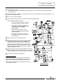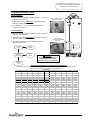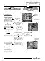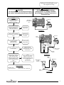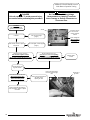
1
COMMERCIAL 24 VOLT FLUE DAMPER
SERIES WATER HEATER
Gas Water Heaters
SERVICE
MANUAL
Troubleshooting Guide
and Instructions for Service
(To be performed ONLY by
qualified service providers)
Models Covered
by This Manual:
For The Bradford White
“D” Series Models:
D38T155
D75T(125,160,300)
D65T(370,399)
D80T(180,199,250)
D80T(425,505)
D100T(199,250)
D80L(399,450,505)
D100L(199,250,270,300)
D100S(199,250)
Manual 47324A
Save this manual for future reference
Table of Contents
Page
Introduction
3
---
Tool required for service
3
---
Sequence of Operation
4
---
Troubleshooting
5
---
Thermostat Circuit Testing
6
D24-I
Pilot Operation Testing
8
D24-II
Main Burner Operation testing
10
D24-III
Main Burner & Pilot Removal & Inspection
12
D24-IV
Flue Baffle Removal & Inspection
14
D24-V
Anode Removal & Inspection
15
D24-VI
Generic Parts List
16
---
Glossary of Terms
19
---
Page 2
2
eF Service Procedure
Introduction
It is intended for this manual to be used by qualified service personal for the primary purpose of
troubleshooting analysis and repair of the Bradford White 24 Volt Flue Damper Series Water
Heater. Understanding the sequence of operation section of this manual will contribute greatly to
troubleshooting this product.
Troubleshooting begins simply by resetting the water heater and observing the lighting sequence
to determine failure mode. This step by step procedure beginning on page 5 will direct the service
provider to a series of test procedures to determine root cause of failure.
Contact Technical support immediately if diagnosis is not determined using the methods described
in this service manual.
Tools Required for Service
Manometer:
Two types available, a liquid “U” tube type or a digital (magna-helic)
type. This device is used to measure gas and/or air pressures and
vacuum.
Multi-Meter:
A digital type is strongly recommended. This device is used to measure
electrical values. The meter you select must have the capability to
measure volts AC, volts DC, Amps, micro-amps and ohms.
Thermometer:
Used to measure water temperature. An accurate thermometer is
recommended.
Water Pressure Gage:
Used to measure water supply pressure. Also used to determine tank
pressure by adapting to the drain valve of the heater.
Jumper Leads:
A length of wire (12" min.) with alligator clip at both ends.
Various Hand Tools:
Pipe wrench, channel locks, open end wrench set, 12" crescent wrench,
Allen wrench set, torx bit set, screw drivers (common & phillips), long
reach (12") magnetic tip phillips head screw driver #2 tip, ¼" nut driver,
pliers (common & needle nose), socket set including a 1-1/16 deep well
socket, wire cutters, wire strippers, wire crimpers, torpedo level, small
shop vac, step ladder, and flashlight.
Page 3
3
Sequence of Operation
1
Thermostat calls for heat.
The relay closes on the thermostat board, sending 24 volts from the “COM” terminal of the thermostat board
to the flue damper.
2
Flue damper begins to rotate open. Once damper is full open, 24 volts is allowed to continue through damper to the
“TH” terminal of ignition module.
3
LED on ignition module illuminates.
4
Trial for ignition (90 second trials, 3 trials with 30 second pause between trials).
Ignition module simultaneously sends:
1. 24 volts from “MV/PV” terminal, to “MV/PV”
terminal of gas valve (common terminal).
2. 24 volts from “PV” terminal, through the
ECO located in the lower thermister, to “PV”
terminal of gas valve to establish
gas flow at pilot.
3. Low current high voltage from “spark”
terminal, to generate spark at the pilot and
ignite pilot gas flow.
4. Pilot flame proving signal (measured in
micro-amps). from the “sense” terminal, to
prove pilot flame.
5
Once pilot flame is proven, sparking will stop.
6
Once sparking stops, 24 volts is sent from “MV” terminal on
module, to “MV” terminal on gas valve to establish main
burner gas flow. Main burners ignite from the pilot flame.
The ignition module constantly monitors pilot flame. If pilot
flame is lost, pilot and main burner are shut down. After a
30 second purge period, module will attempt to re-light pilot
beginning at sequence 4 above.
7
Main burner fires until the thermostat is satisfied. The relay on
the thermostat board opens, interrupting 24 volts through the
damper and ignition module. Pilot and main burner is turned off.
8
Flue damper rotates to the closed position.
LOCKOUT CONDITION
Ignition module will “lockout” if the pilot can not be lit after 3
ignition trials. The ignition module indicates a lockout condition
by the continues flash of the LED located on the module.
Lockout reset is accomplished by interrupting 120 VAC to the
unit for at least 5 seconds.
WIRING DIAGRAM
Page 4
4
TROUBLESHOOTING
CAUTION
Use Caution Not to Damage Connectors when making Voltage Measurements or Jumping Terminals
DANGER
120 volt exposure. Use Caution
To Avoid Personal Injury.
1
Verify Primary and secondary voltage
at the transformer
(see photo 1)
Rear terminals
primary
(120 VAC)
If LED on ignition module is flashing,
reset water heater by turning “OFF”
power. Wait 5 seconds and turn
power back “ON”
Ignition Module LED Status
OFF = No power to module
ON = Module has power
Flashing = Module is in lock-out
Forward terminals
secondary
(24 VAC)
Rotate thermostat dial to the
highest setting.
Does damper vane Move to the full
open position?
See thermostat testing
(page 6).
N
Y
Does LED light on ignition module
illuminate?
N
Y
Is there pilot flame?
Ignition module
N
Remove damper from
heater and
Jump black & yellow wires
of heater harness
(see photo 2)
Is there 24 VAC between Y
terminals “TR” & “TH” of the
ignition module?
(see photo 1A)
N
N
Does LED light on
ignition module
illuminate?
Replace ignition module
Check for debris limiting
damper rotation, if no
debris, replace damper
1A
Check damper harness
connection.
See pilot will not light
(page 8)
Check for 24 VAC
across terminals
“TR” & “TH”
Y
Does Main burner operate?
Y
N
See pilot lights, no flame
signal.
(page 9)
Y
Does burner continue until thermostat N
set point is reached?
See main burner
short cycle
(page 11).
Damper vane show in open position. If damper
is closed, disconnect from harness and
REMOVE damper from water heater.
2
Y
Does flue damper rotate to the closed N
position?
Check for debris limiting
damper rotation, if no
debris, replace damper
Y
System okay.
Harness shown disconnected from damper
with BLACK and YELLOW wires jumped.
Page 5
5
SERVICE PROCEDURE D24-I
Thermostat Circuit Testing
DANGER
120 volt exposure. To avoid personal injury,
use caution while performing this procedure.
CAUTION
Be Careful When Making Voltage
Measurements or Jumping Terminals
Not to Damage or Deform Connectors or
Connector Pins.
This procedure assumes the flue damper is in working order. Be sure damper opens under its own power when the
thermostat circuit is by-passed. Damper must be open or removed during this test. Do not force damper open using your
hands or tools.
With power on to water heater,
Verify Primary and secondary voltage at
the transformer
(see photo 3)
3
4
Rear terminals
primary
(120 VAC)
THERMOSTAT CIRCUIT BY-PASS
Forward terminals
secondary
(24 VAC)
Turn power “OFF” to water heater and
locate thermostat board inside control box
of water heater. Disconnect YELLOW wires
from the thermostat board at location
“N.O.” & “COM”. Use a jumper to connect
these two wires together
(see photos 4 & 5).
DANGER
5
Do not leave thermostat jumper in
place for normal operation.
Turn power on to water heater.
Does LED on ignition module illuminate?
(see photo 6)
N
Verify transformer voltage
(see photo 3)
N
See pilot operation testing
(page 8)
Y
Does pilot and main burner operate?
Y
Turn power “OFF”.
Remove jumper and re-connect wires to
thermostat board. Wires are identified for
proper connection to board.
LED Location
6
Disconnect ORANGE potentiometer (temp
adjustment dial) wires from thermostat
board (see photo 7)
Check potentiometer for proper resistance values of:
Greater then 4800 Ohms with dial at minimum setting.
Less than 50 Ohms with dial at maximum setting.
(see photo 8).
Are readings correct?
8
N
Y
Page 6
6
7
Replace potentiometer
Check Thermisters
(see page 7)
SERVICE PROCEDURE D24-I
Thermostat Circuit Testing
Thermister Resistance Testing
Upper Thermister:
1. Determine resistance value of upper thermister. Test across
grey wires. (see photo 9).
Upper thermister location
(applicable models)
2. Draw quart of water off T&P valve. Using a thermometer,
determine water temperature.
9
3. Use table below to verify correct resistance per water
temperature measured.
Lower Thermister:
1. Determine resistance value of lower thermister. Test across
blue wires. (see photo 10).
2. Draw quart of water off Drain Valve. Using a thermometer,
determine water temperature.
Lower thermister
access located inside
control box.
3. Use table below to verify correct resistance per water
temperature measured.
Are readings
correct?
N
10
Replace
thermister
Y
Check harness
N
continuity.
Continuity okay?
Replace
harness
CAUTION
Be Careful When Making Resistance
Measurements Not to Damage or
Deform Connectors or Connector Pins.
Y
Replace
thermostat
board
Thermister Resistance at Various Temperatures
Example: If water temperature is 84°F, then the resistance through the sensor would be 8449 (see shaded area).
NOTE: Sensor resistance increases as the temperature falls.
°F
40
50
60
70
80
90
100
110
120
130
140
150
160
170
180
190
200
0
26109
19906
15314
11884
9299
7333
5827
4663
3758
3048
2488
2043
1688
1402
1170
982
828
1
25400
19383
14925
11592
9078
7165
5697
4562
3679
2986
2439
2004
1656
1376
1150
965
814
2
24712
18876
14548
11308
8862
7000
5570
4464
3602
2925
2391
1966
1625
1351
1129
949
801
3
24045
18383
14180
11032
8653
6839
5446
4368
3527
2866
2344
1928
1595
1327
1110
933
788
In Degrees
4
23399
17905
13823
10763
8449
6683
5326
4274
3453
2808
2298
1891
1566
1303
1090
917
775
F
5
22771
17440
13477
10502
8250
6531
5208
4183
3382
2752
2253
1856
1537
1280
1071
901
762
6
22163
16990
13140
10248
8057
6383
5094
4094
3312
2697
2209
1820
1509
1257
1053
886
749
7
21573
16553
12812
1000
7869
6238
4982
4006
3244
2643
2166
1786
1481
1235
1035
871
737
8
21000
16128
12494
9760
7685
6098
4873
3922
3177
2590
2124
1753
1454
1213
1017
857
725
9
20445
15715
12185
9526
7507
5961
4767
3839
3112
2538
2083
1720
1427
1191
999
842
713
Page 7
7
SERVICE PROCEDURE D24-II
Pilot Operation Testing
CAUTION
Be Careful When Making Voltage
Measurements or Jumping Terminals
Not to Damage or Deform Connectors or
Connector Pins.
DANGER
120 volt exposure. To avoid personal injury,
use caution while performing this procedure.
Condition:
Pilot will not light,
Ignition module LED is “ON”
Reset heater by turning power
“OFF”. Wait 5 seconds and turn
power “ON”. When LED of
ignition module turns “ON” does
ignition module send “spartk”
signal (buzzing or clicking sound)
11
N
Replace ignition
module
Y
Is there spark at the
pilot?
Check across
“MV/PV” & “PV”
terminals
Check across “MV/PV”
& “PV” Wire leads to
gas valve
Check for:
Loose or damaged ignition wire
Grounded pilot electrode
Damaged pilot.
N
Y
Is there 22-27 volts AC output across
terminals “MV/PV” & “PV” of Ignition
Module? Disconnect wires & check
across terminal of module.
(see photo 11)
N
12
Replace ignition
module
Y
Is there 22-27 volts AC input
across wire leads
“MV/PV” & “PV”
at Gas Valve?
(see photo 12)
Y
N
Loosen pilot tubing connection at
the gas valve and soap test.
Is there pilot gas flow out of the
gas valve?
Y
Check for clogged or kinked
pilot tube, clogged pilot orifice.
Clean or replace as needed.
(see page 13)
N
Tighten pilot tube connection at
the gas valve. Check incoming
gas pressure to water heater. if
okay, replace gas valve
Check across RED
wire leads of lower
thermister (ECO).
13
Check continuity across ECO
(RED) leads of lower thermister
(see photo 13)
Is continuity okay?
N
ECO Specifications
Opens between 181°F/201°F
Closes between 160°F/100°F
Y
Check wire harness for damage
or loose connections. Repair or
replace as needed.
Page 8
8
SERVICE PROCEDURE D24-II
Pilot Operation Testing
DANGER
120 volt exposure. To avoid personal injury,
use caution while performing this procedure.
Condition:
Pilot lights, no flame signal.
Module continues to spark until
system “Lock Out”.
Main burner will not light.
Check for loose or damaged
flame sense lead from pilot to
module. (see illustration 1).
Is flame sense lead okay?
CAUTION
Be Careful When Making Voltage
Measurements or Jumping Terminals
Not to Damage or Deform Connectors or
Connector Pins.
Flame rod
White flame
sense lead from
pilot
N
Repair wire lead
or replace pilot.
Illustration 1
Y
Check for loose or damaged
N
ground wire(s). Are ground wires
okay?
Repair ground
wire(s) or replace
as needed.
Y
Check venting conditions or
negative pressure
Is vent system okay?
N
Flame rod
Meter
Probe
Correct improper
venting condition.
Multi-meter set
to micro-amp
setting (ȝA)
Y
Is heater condensing causing
pilot interruption?
Determine cause for
condensing and correct.
Under sized heater or high
demand periods
Y
White wire lead
from pilot
Meter
Probe
N
Disconnect white flame sense
lead from ignition module at the
“SENSE” location. Set multimeter to the “Micro Amps”
setting (ȝA) (see note). Check
micro amp reading. Be sure
module is sparking during this
test.
(see illustration 2)
NOTE:
If multi meter is not capable of
testing micro amps, check
continuity of sense lead. If no
continuity, clean pilot flame rod
or replace pilot.
(see illustration 3)
Illustration 2
Meter
Probe
Multi-meter set
to check
continuity.
Flame rod
Micro-amp readings
0.000 Micro Amp =
1.0 micro amp or less =
Replace module.
Clean pilot flame rod or replace pilot.
Meter
Probe
Illustration 3
Page 9
9
SERVICE PROCEDURE D24-III
Main Burner Operation Testing
CAUTION
Be Careful When Making Voltage
Measurements or Jumping Terminals
Not to Damage or Deform Connectors or
Connector Pins.
DANGER
120 volt exposure. To avoid personal injury,
use caution while performing this procedure.
Condition:
Main burner will not light,
Ignition module LED is “ON”
Ground
Is Pilot lit?
Disconnect “brown”
wire from “MV”
location of ignition
module.
See “pilot will not light”
(page 8).
N
Check voltage from
“MV” Terminal of
Ignition module
& ground.
Y
Does module continue to spark
with pilot lit?
14
See “Pilot lights, no flame signal”
(Page 9).
Y
N
Disconnect “brown” wire from
“MV” terminal of ignition module.
Is there 22-27 volts AC across
“MV” terminal of Ignition Module & ground?
(see photo 14)
N
Be sure module LED is “ON”,
pilot is lit and module is not sparking
Recheck voltage across
“MV” terminal of Ignition Module & ground.
Is voltage present?
Y
N
Replace ignition
module
Y
Reconnect brown wire
to ignition module.
Disconnect brown wire lead from
“MV” terminal of gas valve.
Is there 22-27 volts AC across
brown wire lead & ground
(see photo 15)
Brown wire disconnected
from “MV” terminal of gas
valve
Y
Check incoming gas pressure to
gas valve. if okay,
replace gas valve.
N
Check wire harness for damage or
loose connections. Repair or replace
as needed.
Page 10
10
15
Ground lug of
gas valve
SERVICE PROCEDURE D24-III
Main Burner Operation Testing
CAUTION
Be Careful When Making Voltage
Measurements or Jumping Terminals
Not to Damage or Deform Connectors or
Connector Pins.
DANGER
120 volt exposure. To avoid personal injury,
use caution while performing this procedure.
Condition:
Main burner short cycle
Check gas (line) pressure to the
water heater.
Minimum line pressure should be
5.5" W.C.
Is gas pressure within proper
specification? (see photo 16)
Check venting conditions,
clogged vent, down drafts or
negative building pressure
Is vent system okay?
Is there sufficient combustion air
being supplied to the water
heater?
Determine cause of incorrect gas
pressure and correct.
N
N
Correct improper
venting condition.
Provide proper
combustion air to
water heater.
Y
Check for unstable pilot flame or
oxidize flame rod on pilot
causing weak pilot signal
(See page 9)
Line gas
pressure port
Check burner tubes for scale or
debris build-up. Clean burner as
necessary.
(see page 12)
Check tank flues for blockage or
debris build-up causing
restriction.
(see page 14)
16
Manifold
Pressure Port
Page 11
11
SERVICE PROCEDURE D24-IV
Main Burner & Pilot
Removal and Inspection
WARNING
Heater components may be HOT when performing the following steps in this procedure.
Take necessary precaution to prevent personal injury.
Gas Valve
Wire Leads
Main Burner Removal
Gas Valve
Control Knob
Step 1.
Disconnect (un-plug) water heater from
electrical supply.
Step 2.
Turn “OFF” gas supply to water heater.
Step 3.
Rotate gas valve control knob to the “OFF” position
(see photo 17).
Step 4.
Disconnect Gas supply line from the gas valve
(see photo 17).
Step 5.
Disconnect wire leads from gas valve
(see photo 17).
Gas Supply
Line
17
18
Step 6.
Disconnect white flame sense wire & orange ignition
wire from Ignition module (see photo 18).
Step 7.
Remove the two burner rack mounting screws.
Step 8.
Slide complete burner rack out from heater
(see photo 19).
Step 9.
To install burner, reverse above procedure.
Step 1.
Burner tubes should be free of any flue
scale or other debris. Clean
burner tubes using a stiff brush and/or
shop vac. Burner ports should have uniform
openings. Replacement is recommended for
burners where port area is deteriorated or
other unintended openings are present.
Step 2.
Insure pilot shield is in place (see photo 20).
Step 3.
Inspect pilot position to insure smooth burner
ignition from pilot flame. Pilot should be
mounted using the two mounting screws thru
the burner support bracket resulting in a level
pilot position.
Flame sense
wire
Ignition wire
19
Main Burner Inspection
Pilot
Shield
20
Page 12
12
Burner Rack
Mounting
Screw
SERVICE PROCEDURE D24-IV
Main Burner & Pilot
Removal and Inspection
Pilot Shield
Pilot Burner Removal
Step 1.
With burner rack removed from heater, disconnect
pilot tube connection from gas valve
Step 2.
Remove the two pilot burner mounting screws
securing the pilot and pilot shield in place.
Step 3.
Remove pilot shield and pilot from burner rack.
Step 4.
To install pilot burner and pilot shield, reverse above
procedure. Be sure to reconnect green ground wire.
Ground Wire
Location
Pilot & Pilot Shield
Mounting Screws
Pilot Burner Inspection
Step 1.
Inspect pilot for the following:
a) Broken or cracked ceramic insulators. If found,
pilot must be replaced.
Flame
Rod
b) Damaged electrode or flame sense wire. If found,
pilot must be replaced.
c) Oxidation build-up on flame rod. Clean flame rod
or replace pilot as necessary.
Step 2.
Inspect pilot orifice:
a) Remove 7/16" ferrule nut from bottom of pilot.
b) Remove pilot tube and orifice from pilot.
Ceramic
Insulators
Pilot
Orifice
Ignition
Wire
7//16"
ferrule
Nut
Flame Sense
Wire
c) Inspect pilot tube for blockage. Clean or replace
as necessary.
d) Inspect pilot orifice for blockage. Clean or replace
as necessary.
Aluminum
Pilot Tubing
Page 13
13
SERVICE PROCEDURE D24-V
Flue Baffle Removal, Inspection
WARNING
Heater components may be HOT when performing the following steps in this procedure.
Take necessary precaution to prevent personal injury.
Step 1.
Disconnect (unplug) water heater from electrical supply.
Step 2.
Disconnect venting from draft diverter and remove draft diverter from top of water heater.
Step 3.
Disconnect flue damper from wire harness and remove flue damper from top of water heater.
Step 4.
If required disconnect top plumbing connection from top of water heater.
Step 5.
Remove screws holding jacket head to top of water heater and remove jacket head
from top of water heater.
Step 6.
Remove insulation from top of water heater to expose collector cover.
Step 7.
Remove screw from side (or top) of collector cover and remove collector cover from
water heater.
Step 8.
Remove flue baffles from heater. Note, it may be necessary to use pliers to loosen and
remove baffles from flue tubes.
Step 9.
Visually inspect flue baffles. Flue baffles should show signs of oxidation, this is normal.
If the oxidation has deteriorated any portion of the flue baffle, replacement is
recommended. If any restrictors are missing, replacement is recommended.
Step 10.
Upon completion of inspection or subsequent replacement, reinstall flue baffles into
heater.
Step 11.
Reinstall collector cover and insulation over collector cover.
Step 12.
Reinstall jacket head, flue damper and draft diverter. Reconnect venting.
Step 13.
Reconnect plumbing connection to top of water heater if required.
Page 14
14
SERVICE PROCEDURE D24-VI
Anode Removal and Inspection
WARNING
Heater components may be HOT when performing the following steps in this procedure.
Take necessary precaution to prevent personal injury.
Step 1.
Disconnect (unplug) water heater from electrical supply.
Step 2.
Turn “OFF” water supply to water heater.
Step 3.
Open a near by hot water faucet to relieve tank pressure.
Step 4.
Connect hose to drain valve of water heater and route to an open drain. Open
drain valve and drain approximately 1 gallon of water from the water heater. Close drain
valve and disconnect drain hose from water heater.
Step 5.
Disconnect venting from draft diverter and remove draft diverter from top of water heater.
Step 6.
Disconnect flue damper from wire harness and remove flue damper from top of water heater.
Step 7.
If required disconnect top plumbing connection from top of water heater.
Step 8.
Remove screws holding jacket head to top of water heater and remove jacket head
from top of water heater.
Step 9.
Remove insulation from top of water heater to expose collector cover.
Step 10.
Remove screw from side (or top) of collector cover and remove collector cover from
water heater.
Step 11.
Locate and remove anode rods from top of water heater (1-1/16 hex socket).
Step 12.
Visually inspect anode rod. Anode rod should show signs of depletion, this is normal.
If the depletion is half the original diameter (approximately ¾"), replacement is
recommended. If any of the steel core of the anode is exposed, replacement is
recommended.
Step 13.
Upon completion of inspection or subsequent replacement, reinstall anode rods into
heater.
Step 14.
Reinstall collector cover and insulation over collector cover.
Step 15.
Reinstall jacket head, flue damper and draft diverter. Reconnect venting.
Step 16.
Reconnect plumbing connection to top of water heater if required.
Step 17.
Restore water supply and power to water heater.
Page 15
15
Generic Parts List
1. Draft Diverter w/Leg Kit.
2. Draft Diverter.
3. Draft Diverter Leg.
4. Damper Outlet Reducer.
5. Flue Damper.
6. Hot Outlet Nipple.
7. Cold Water Inlet Dip
Tube.
8. Hex Head Anode.
9. Flue Baffle.
10. Flue Reducer.
11. Flue Core.
12. 1" x ¾" Reducer Bushing.
13. Nipple T&P Valve.
14. T&P Valve.
15. Cleanout O-Ring.
15A. Cleanout Gasket (ASME).
16. Cleanout Access Cover.
16A. Cleanout Access Cover (ASME).
17. Cleanout Cover Screw.
17A Cleanout Cover Screw (ASME)
18. Cleanout Jacket Cover.
19. Cleanout Jacket Cover Screw.
20. Burner Assembly Complete.
Page 16
16
21. Brass Drain Valve.
22. Cold Water Inlet Nipple (side).
23. Gas Valve Harness.
24. Damper Harness.
25. Lower Thermister.
26. Control Box Assembly Complete.
27. Hot Water Outlet Nipple (side).
28. Upper Thermister.
29. Utility Cover.
30 ASSE Approved Nixing Valve.
Generic Parts List
1A. Draft Panel.
2A. Burner Rack.
3A. Burner Tube.
4A. Gas Valve.
5A. Burner Manifold.
6A. Main Burner Orifice.
7A. Pilot Shield.
8A. Pilot Burner.
9A. Pilot Orifice.
10A. Pilot Tubing.
11A. Pilot Mounting Screw.
12A. Burner Tube Support.
13A. Manifold Bracket.
14A. C-Cane Manifold.
15A. Manifold Straight.
16A. Manifold Bracket.
17A. 90° Street Elbow Black.
18A. 1" Down Pipe Nipple Black.
19A. 1" 90° Elbow Black.
20A. 1" Manifold Ball Valve.
21A. 1" Close Nipple Black.
22A. Pilot Regulator.
23A. Pilot Solenoid.
24A. 1/8" Pipe Plug Black.
25A. 1" x 1/8" Reducer Bushing.
26A. 1" pipe Tee Black.
27A. 1" Close Nipple Black
28A. 1" Union Black.
29A. 1" 90° elbow Black.
Page 17
17
Generic Parts List
1C. Temperature Control Knob.
2C. Potentiometer Gasket.
3C. Potentiometer (Temperature Control).
4C. 7/8" Snap Bushing.
5C. Temperature Scale Plate.
6C. Control Box Panel.
7C. Terminal Strip.
8C. Ground Terminal.
9C. Power Cord train Relief Bushing.
10C. Power Cord.
11C. Pilot wire Strain Relief Bushing.
12C. 7/8" Snap Bushing.
13C. Transformer.
14C. Thermostat Board.
15C. Ignition Module.
16C. Control Box Cover.
Page 18
18
Glossary of Terms
AC
BTU/H
CO
CO2
DC
ECO
GFI
GPM
Hz
LED
NOx
NPT
PSI
VA
VAC
W.C.
°C
°F
ȝA
Alternating Current
British Thermal Units
Carbon Monoxide
Carbon Dioxide
Direct Current
Energy Cut Off
Ground fault interrupt
Gallons per Minute
Hertz
Light Emitting Diode
Oxides of Nitrogen
National Pipe Thread
Pounds per Square Inch
Volt Amps
Volts Alternating Current
Inches of Water Column
Degrees Centigrade
Degrees Fahrenheit
Micro Amp
NOTES
Page 19
19
Email
[email protected]
[email protected]
www.bradfordwhite.com