1
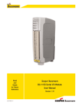
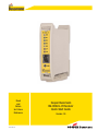
Read
and
Retain
for Future
Reference
3A1578Rev1.9
Cooper Bussmann
BU-905U-L-R Receiver
Quick Start Guide
Version 1.9
Cooper Bussmann BU-905U-L-R Receiver Quick Start Guide
About this Document
This document is the Cooper Bussmann BU-905U-L Wireless I/O Receiver Unit Quick Start Guide and contains the following sections:
Section
Read this section if you want to …
Basic steps for using your unit
Learn the basic steps for installing and using your unit.
Factory default configuration
Understand how the transmitter sends information to the receiver.
Unit components
Understand the different parts of your unit.
Antenna installation
Learn how to install an antenna with your unit.
Resetting factory defaults
Reset your unit to the original factory default settings.
Linking transmitter and receiver units
Link your units to work as a dedicated pair.
Safety information
Understand important safety information related to your unit.
NOTE: You must read this information before installing your unit.
Specifications
Know technical information about your unit.
For more information, see the next sections.
Basic Steps for Using Your Unit
This document describes how to configure your unit using the default factory configuration that lets you easily setup your network as a simple
send/receive network using a dedicated pair of transmitter and receiver units.
The basic steps for using your unit are:
1. Connect the antenna power supply and transducer signals using the instructions in this document. Power supply and transducer connection is
described in the section Unit components and connections. Antenna connection is described in the section Antenna installation. For more
information, see the BU-905U-L Installation Manual.
2. Reset the transmitter and receiver units to the factory default configurations.
3. Link the transmitter and receiver units to work as a dedicated pair.
4. Bench test your configuration before deploying.
NOTE: You can also configure your network using a user-defined customized configuration that lets you set specific information about your
network. For more information on setting a user-defined customized configuration, see the BU-905U-L User Manual on the enclosed CD.
Factory Default Configuration
When you configure the units using the configuration in this document, the inputs from the transmitter are sent to the outputs at the receiver
as follows:
2
BU-905U-L-T (Transmitter)
Sends
BU-905U-L-R (Receiver)
Digital Input 1
Digital Output 1
Digital Input 2
Digital Output 2
Analogue Setpoint
Digital Output 3
Analogue input (4-20 mA)
Analog output (4-20 mA)
Thermocouple Input (Not used) &
Setpoint Output (Local indication)
Communication Failure (Comes on if no messages from BU-905U-L-T)
System OK (On if system OK)
System OK (On if system OK)
www.cooperbussmann.com/BussmannWirelessResources
3A1578Rev1.9
Cooper Bussmann BU-905U-L-R Receiver Quick Start Guide
Unit Components and Connections
Your BU-905U-L-R receiver unit has the following components and terminal connections:
IMPORTANT ELECTRICAL SAFETY INFORMATION
In order to comply with Electrical Safety Regulations, this module must be installed in an Electrical AND Fire enclosure. This enclosure may be a
single or multiple enclosures. Access to the module is to be made by a Service Person only.
In order to comply with Electrical Safety Standards, when connecting SELV AND voltages which are greater than SELV (30Vac or 60Vdc) together,
then Relay Output 2 must NOT be used in order to provide sufficient isolation between the outputs
3A1578Rev1.9
www.cooperbussmann.com/BussmannWirelessResources
3
Cooper Bussmann BU-905U-L-R Receiver Quick Start Guide
Front Panel Components
SMA Antenna Connector at Top of Unit
Indicator LEDs
RS232 Configuration Port
RSSI Push-Button
The LEDs on the front panel indicate the unit status:
LED Status
Indicates
None
No power supply.
OK LED Green
Current status of the unit OK.
OK LED Red
Fault condition detected in unit.
RX LED Flashes
Receiving Message.
CF LED ON
Module Communication Failure Output is active.
PG LED on
Configuration Cable Connected.
Output LED ON
The Output LEDS (i.e., D1, D2, D3) light when the corresponding output is active.
LEDs with RSSI Push
Button Pressed
Output LED flashing
quickly
4
D1
Relay output D1 is ON (Contact Closed).
D2
Relay Output D2 is ON.
D3
Relay Output D3 is ON.
When you press the RSSI push button, the unit shows the signal strength by lighting the LEDs
from the bottom to the top. Signal strength is the strength of the last message received that
was addressed to this station.
LED
Signal Strength
LED
Signal Strength
D1
More than -85 dBm
RX
More than -100 dBm
D2
More than -90 dBm
CF
More than -105 dBm
D3
More than -95 dBm
PG
Always on during RSSI test
If an output is in communication failure, the corresponding LED flashes at 5Hz.
D1
Relay Output D1 is in communication failure.
D2
Relay Output D2 is in communication failure.
D3
Relay Output D3 is in communication failure.
PG
Analog output is in communications failure.
www.cooperbussmann.com/BussmannWirelessResources
3A1578Rev1.9
Cooper Bussmann BU-905U-L-R Receiver Quick Start Guide
Antenna Installation
Resetting Your Unit to Factory Defaults
You must reset the receiver unit to factory defaults before linking the transmitter and receiver units.
To reset the default factory configuration:
1. Press and hold the RSSI push button.
2. Power on the BU-905U-L-R receiver.
3. The BU-905U-L-R receiver flashes all LEDs at medium flash (i.e., 1.6Hz).
NOTE: If the LEDs do not flash, you must repeat steps 1 and 2 until the LEDs flash before continuing.
4. Release the RSSI push button within 5 seconds.
5. Within a further 60 seconds, press and hold the RSSI push button for 5 seconds (until the LEDs stop flashing) and then release.
6. The BU-905U-L-R receiver lights all LEDs for 2 seconds before returning to normal operation.
NOTE: If the LEDs do not light, you must repeat the process from step 1 until the LEDs light before continuing.
7. You can now link the transmitter and receiver units.
3A1578Rev1.9
www.cooperbussmann.com/BussmannWirelessResources
5
Cooper Bussmann BU-905U-L-R Receiver Quick Start Guide
Linking Your Transmitter and Receiver Units
You must reset the transmitter unit to factory defaults (to disable encryption) before linking the transmitter and receiver units.
For more information, see the BU-905U-L-T Transmitter Quick Start Guide.
NOTE: You must complete the linking process in 60 seconds.
To link the transmitter and receiver units:
1. Press and hold down the RSSI Pushbutton on the receiver.
2. Power on the receiver while holding down the RSSI Pushbutton
3. Release the RSSI Pushbutton as soon as the Receiver LEDS flash (within 5 seconds of powering the receiver).
4. The receiver will flash all LEDs for a maximum 60 seconds while it tries to link to the transmitter.
5. Power on the transmitter. The transmitter sends a special “Link” message to allow the receiver to recognize the transmitter.
6. When the units link, the receiver lights all LEDs for 2 seconds before returning to normal operation.
NOTE: If the receiver LEDs continue flashing within the 60 seconds, the units are not linked and you should retry the linking process by powering
the transmitter off and on again. If you exceed the 60 seconds, you must restart the linking process from step 1.
7. You can now bench test your configuration before deploying.
Safety information
Thank you for selecting the BU-905U-L-R receiver for your telemetry needs. We trust it will give you many years of valuable service. To ensure
your BU-905U-L-R receiver enjoys a long life, double-check ALL your connections with the user’s manual before powering on the unit.
WARNING: Incorrect termination of supply wires may cause internal damage and will void warranty.
Exposure to RF energy is an important safety consideration. The FCC has adopted a safety standard for human exposure to radio frequency
electromagnetic energy emitted by FCC regulated equipment as a result of its actions in Docket 93-62 and OET Bulletin 65 Edition 97-01.
FCC Notice When Used in USA: BU-905U-L Wireless I/O Module
Part
Additional information
15
This device has been tested and found to comply with the limits for a Class B digital device, pursuant to Part15 of the FCC
rules (Code of Federal Regulations 47CFR Part 15). Operation is subject to the condition that this device does not cause
harmful interference.
90
This device has been type accepted for operation by the FCC in accordance with Part90 of the FCC rules (47CFR Part 90).
See the label on the unit for the specific FCC ID and any other certification designations.
Industry Canada: BU-905U-L Wireless I/O Module
RSS-119 - This device has been type accepted for operation by Industry Canada in accordance with RSS-119 of the Industry Canada rules. See
the label on the unit for the specific Industry Canada certification number and any other certification designations.
NOTE: Any changes or modifications not expressly approved by Cooper Bussmann P/L could void the user’s authority to operate this equipment.
To operate this equipment legally the user must obtain a radio-operating license from the government agency. This is done so the government can
coordinate radio users in order to minimize interference.
Safety Information - FCC Notice
This device complies with Part 15.247 of the FCC Rules. Operation is subject to the following two conditions:
• This device may not cause harmful interference; and
• This device must accept any interference received, including interference that may cause undesired operation
NOTE: This equipment is suitable for use in Class 1 Division 2 groups A, B and C or non-hazardous locations only.
6
www.cooperbussmann.com/BussmannWirelessResources
3A1578Rev1.9
Cooper Bussmann BU-905U-L-R Receiver Quick Start Guide
UL Notice:
1. The Wireless I/O module is to be installed by trained personnel / licensed electricians only and installation must be carried out in accordance
with the instructions listed in the Installation Guide and applicable local regulatory codes.
2. The units are intended for Restricted Access Locations.
3. The Wireless I/O module is intended to be installed in a final enclosure, rated IP54, before use outdoors.
4. The Equipment shall be powered using an external Listed Power Supply with LPS outputs or a Class 2 Power Supply.
5. The Wireless I/O module must be properly grounded for surge protection before use.
Unit Specifications
Input/Output
Number
Additional Information
Digital Outputs
3
Voltage-free contacts rated at 250Vac 1A, 30Vdc 1A.
2 for digital inputs and 1 for setpoint.
Status Outputs
2
Separate System OK and communication failure output.
Analog Output
1
16-bit resolution, 0.1% accuracy, single-ended source output.
Power Supply
1
9-30Vdc 0.25 Amp CSA certified Class 2 power supply. For use in Class I Div 2
hazardous locations, the power supply must be approved for Class I Div 2 use.
WARNING: Explosion hazard - do not disconnect while circuit is live unless area
is known to be non-hazardous.
Radio Receiver
1
High sensitivity FHSS UHF radio receiver.
Frequency
902 – 928MHz
Actual frequency range depends on country.
Sensitivity
-110 dBm
At BER 8%.
Document Information
Quick Start Guide Cooper Bussmann BU-905U-L Wireless I/O Receiver Unit Version 1.9
Cooper Bussmann Contact Details
Telephone
636-527-1270
Fax
636-527-1607
E-mail
[email protected]
Website
www.cooperbussmann.com
3A1578Rev1.9
www.cooperbussmann.com/BussmannWirelessResources
7
Customer Assistance
Customer Satisfaction Team
Application Engineering
Available to answer questions regarding Cooper
Bussmann products & services Monday-Friday,
8:00 a.m. – 4:30 p.m. for all US time zones.
Contact:
s Toll-free phone: 855-287-7626 (855-BUSSMANN)
s Toll-free fax: 800-544-2570
s E-mail: [email protected]
Technical assistance is available to all customers.
Staffed by degreed engineers, this application support
is available Monday-Friday, 8:00 a.m. – 5:00 p.m. CT
Contact:
s Phone: 636-527-1270
s Fax: 636-527-1607
s E-mail: [email protected]
s Live Chat: www.cooperbussmann.com
Emergency and After-Hours Orders
Next flight out or will call shipment for time-critical needs.
Customers pay only standard product price, rush freight
charges, & modest emergency service fee. Place these
orders through the Customer Satisfaction Team during
regular business hours. For after-hours, contact:
Online Resources
Visit www.cooperbussmann.com for the following
resources:
s Product search & cross-reference
s Product & technical materials
s Solutions centers for information on topical issues
including arc-flash, selective coordination &
short-circuit current rating
s Technical tools, like our arc-flash calculator
s Where to purchase Cooper Bussmann product
s Phone: 314-995-1342
C 3 – the Enhanced, Online Cooper Customer Center
Provides real time product availability, net pricing, order
status & shipment tracking across six Cooper divisions:
B-line, Bussmann, Crouse-Hinds, Lighting, Power
Systems & Wiring Devices. Available at:
Services
Cooper Bussmann Services team provides engineering
expertise in electrical system reviews, electrical safety
training & component testing for Agency compliance.
Contact:
s www.cooperc3.com
s 877-995-5955 for log-in assistance
s Phone: 636-207-3294
s E-mail: [email protected]
Cooper Bussmann
St. Louis, MO 63178
855.287.7626 (855-BUSSMANN)
w w w. c o o p e r b u s s m a n n . c o m
Your Authorized Cooper Bussmann Distributor is:
©2011 Cooper Bussmann
www.cooperbussmann.com
PDF Only
8
www.cooperbussmann.com/BussmannWirelessResources
3A1578Rev1.9