1
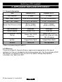
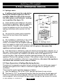
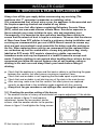
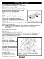
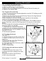
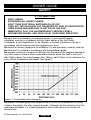
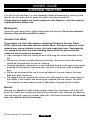
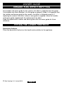
5117291/04 INSTALLER AND OWNER GUIDE Model 939 Heat Engine OPEN DECORATIVE GAS FIRE (GC No. 32-032-54) For further advice please contact the retailer or company from where you purchased your fire INSTALLER: Please leave this guide with the owner © Baxi Heating U.K. Limited 2010. INSTALLER GUIDE THIS APPLIANCE IS FOR USE WITH NATURAL GAS (G20). WHEN CONVERTED USING CONVERSION KIT NO. 0595211 THIS APPLIANCE IS FOR USE WITH PROPANE GAS (G31). THIS APPLIANCE IS SUITABLE ONLY FOR INSTALLATION IN THE UNITED KINGDOM (GB) AND THE REPUBLIC OF IRELAND (IE). © Baxi Heating U.K. Limited 2010. All rights reserved. No part of this publication may be reproduced in any material form (including photocopying), stored in any medium by electronic means (including in any retrieval system or database) or transmitted, in any form or by any means, whether electronic, mechanical, recording or otherwise, without the prior written permission of the copyright owner. Applications for the copyright owner's permission to reproduce any part of this publication should be made, giving details of the proposed use, to the following address: The Company Secretary, Baxi Heating UK Limited, The Wyvern Business Park, Stanier Way, Derby, DE21 6BF. Warning: Any person who does any unauthorised act in relation to a copyright work may be liable to criminal prosecution and civil claims for damages. Because our policy is one of constant development and improvement, details may vary slightly from those given in this publication © Baxi Heating U.K. Limited 2010. Page 2 INSTALLER GUIDE Safety First. This gas fire is CE Approved and designed to meet the appropriate British Standards and Safety Marks. Quality and Excellence. This fire has been manufactured to the highest standards of quality and excellence and was manufactured under a BS EN ISO 9001 quality system accepted by the British Standards Institute. The Highest Standards The manufacturer is a member of SBGI and HHIC (Heating and Hot water Industry Council) that work to ensure high standards of safety, quality and performance. Careful Installation This gas fire must be installed by a competent GAS SAFE REGISTER engineer (GAS SAFE REGISTER or CORGI engineer outside of UK) in accordance with our installer guide and should not be fitted directly on to a carpet or floor of combustible material. © Baxi Heating U.K. Limited 2010. Page 3 INSTALLER GUIDE INSTALLER GUIDE FOR OWNER GUIDE SEE PAGES 26 TO 34 © Baxi Heating U.K. Limited 2010. Page 4 INSTALLER GUIDE CONTENTS Section Heading Page INSTALLER GUIDE OWNER GUIDE 4 - 25 26 - 34 1. SAFETY AND UNPACKING 2. APPLIANCE DATA AND EFFICIENCY 2.1 General information. 2.2 Efficiency. 3. GENERAL INSTALLATION REQUIREMENTS 3.1 Regulations, Standards and Law. 3.2 Ventilation requirements. 3.3 The Atmosphere sensing device (ASD). 3.4 Fireguard requirements. 3.5 Room considerations. 3.6 Chimney preparation. 3.7 Fireplace preparation. 3.8 The hearth. 3.9 Fireplace clearances. 3.10 Installation options. 3.10.1. 'Hole-in-the-wall' Installations 3.11 Suitable Flue. 3.12 Propane appliances. 4. UNPACKING 5. INSTALLATION OF APPLIANCE 5.1 Fireplace size. 5.2 Fireplace flue pull. 5.3 Installation of the burner unit 6. BURNER AND SUPPLY PIPE INSTALLATION 6.1 Preliminary burner checks. 6.1.1 Lighting the fire. 6.1.2 Operating the burner. 6.1.3 Checking the inlet pressure. 7 8 8 8 9 9 10 10 10 10 10 11 11 12 12 12 13 13 16 16 16 16 17 18 19 19 19 19 Continued on next page © Baxi Heating U.K. Limited 2010. Page 5 INSTALLER GUIDE CONTENTS (Continued) Section Heading Page 7. FITTING THE FIREFRONT 8. FITTING THE CERAMIC FUEL EFFECT 9. FULL OPERATING CHECKS 9.1 Spillage check. 9.2 Flame Supervision & Spillage Monitoring System. 9.3 Final Review. 10. SERVICING & PARTS REPLACEMENT 10.1 To remove the complete burner unit. 10.2 To remove the pilot unit. 10.3 To remove the gas valve. 10.4 To remove the piezo generator. 10.5 To grease the control tap. 10.6 To replace the burner. 10.7 To remove the main burner injector. © Baxi Heating U.K. Limited 2010. Page 6 20 20 21 21 21 22 23 24 24 24 25 25 25 25 INSTALLER GUIDE 1. SAFETY AND UNPACKING Installer Before continuing any further with the installation of this appliance please read the following guide to manual handling: The lifting weight of this appliance (DGF burner) is 2 kg. One person should be sufficient to lift the fire. If for any reason this weight is considered too heavy then obtain assistance. When lifting always keep your back straight. Bend your legs and not your back. Avoid twisting at the waist. It is better to reposition your feet. Avoid upper body/top heavy bending. Do not lean forward or sideways whilst handling the fire. Always grip with the palm of the hand. Do not use the tips of fingers for support. Always keep the fire as close to the body as possible. This will minimise the cantilever action. Use gloves to provide additional grip. Always use assistance if required. This product uses fuel effect pieces containing Refractory Ceramic Fibres (RCF), which are man-made vitreous silicate fibres. Excessive exposure to these materials may cause irritation to eyes, skin and respiratory tract. Consequently, it is important to take care when handling these articles to ensure that the release of dust is kept to a minimum. To ensure that the release of fibres from these RCF articles is kept to a minimum, during installation and servicing we recommend that you use a HEPA filtered vacuum to remove any dust and soot accumulated in and around the fire before and after working on the fire. When replacing these articles we recommend that the replaced items are not broken up, but are sealed within a heavy duty polythene bag, clearly labelled as RCF waste. RCF waste is classed as a stable, non-reactive hazardous waste and may be disposed at a landfill licensed to accept such waste. Protective clothing is not required when handling these articles, but we recommend you follow the normal hygiene rules of not smoking, eating or drinking in the work area and always wash your hands before eating or drinking. This appliance does not contain any component manufactured from asbestos or asbestos related products. © Baxi Heating U.K. Limited 2010. Page 7 INSTALLER GUIDE 2. APPLIANCE DATA AND EFFICIENCY 2.1 General information. Gas Natural (G20) Propane (G31) * Inlet Pressure 20 mbar 37 mbar Input - Max. (Gross) 6.85 kW (23,400 Btu/h) 6.7 kW (22,860 Btu/h) Input - Min. (Gross) 2.3 kW (7,850 Btu/h) 4.0 kW (13,650 Btu/h) Burner Test Pressure (Cold) 20.0 ± 1.0mbar (8.0 ± 0.4in w.g.) 37.0 ± 1.0mbar (14.85 ± 0.4in w.g.) Gas Connection 8mm pipe 8mm pipe Burner Injector Cat 82 - 074 Size 132 Copreci Ref. O.D.S 21500/166 Copreci Ref. O.D.S 21500/166 Fitted with RBM 180 -02 injector Ignition Integral Piezo Spark Integral Piezo Spark Aeration Factory set Non-adjustable Pilot & Atmosphere Sensing Device *When converted using kit 0595211 2.2 Efficiency. There are no specific thermal efficiency requirements appropriate to this type of appliance as they are intended for decorative purposes only. For the purposes of SAP the efficiency is classed as 20% for use in the Space Heating Requirements calculation, see Table 4a of SAP. © Baxi Heating U.K. Limited 2010. Page 8 INSTALLER GUIDE 3. GENERAL INSTALLATION REQUIREMENTS 3.1 Regulations, Standards and Law. The installation must be in accordance with these instructions. For the user’s protection, in the United Kingdom it is the law that all gas appliances are installed by competent persons in accordance with the current edition of the Gas Safety (Installation and Use) Regulations. Failure to install the appliance correctly could lead to prosecution. GAS SAFE REGISTER and CORGI require their members to work to recognised standards. In the United Kingdom the installation must also be in accordance with: All the relevant parts of local regulations. All relevant codes of practice. The relevant parts of the current editions of the following British Standards:BS 1251 Fireplace components BS 5440 Part 1 Installation of flues. BS 5440 Part 2 Installation and maintenance of flues and ventilation for gas appliances of rated input not exceeding 70 kW net (1st, 2nd and 3rd family gases). BS 5871 Part 2 Installation - Inset LFE gas fires BS 6461 Part 1 Masonry chimney & flues - Installation BS 6891 Gas pipework installation In England and Wales, the current edition of the Building Regulations issued by the Department of the Environment and the Welsh Office. In Scotland, the current edition of the Building Standards (Scotland) Regulations issued by the Scottish Executive. In Northern Ireland, the current edition of the Building regulations (Northern Ireland) issued by the Department of the Environment for Northern Ireland. In the republic of Ireland the installation must be carried out by a competent person and also conform to the relevant parts of: The current editions of:IS 813 “Domestic Gas Installations” ICP3 IS327 All relevant national and local rules in force. Where no specific instructions are given, reference should be made to the relevant British Standard Code of Practice. © Baxi Heating U.K. Limited 2010. Page 9 INSTALLER GUIDE 3.2 Ventilation requirements. Normal adventitious ventilation is usually sufficient to satisfy the ventilation requirements of this appliance. In GB reference should be made to BS 5871 Part 2 and in IE reference should be made to the current edition of IS 813 “Domestic Gas Installations” which makes clear the conditions that must be met to demonstrate that sufficient ventilation is available. 3.3 The Atmosphere sensing device (ASD). The appliance is fitted with an A.S.D (Atmosphere sensing device). If the appliance closes down after a period of operation for no apparent reason, the consumer should be informed to stop using the appliance until the installation and appliance have been thoroughly checked. The A.S.D will shut the appliance down if an unacceptable amount of harmful products of combustion accumulate. Under no circumstances should the A.S.D be altered or bypassed in any way. Only a genuine manufacturers replacement part should be fitted. The individual A.S.D components are not replaceable. 3.4 Fireguard requirements. A fireguard complying with BS 8423 should be fitted for the protection of young children, the elderly, the infirm and pet animals. 3.5 Room considerations. 3.5.1 This appliance must not be installed in any room that contains a bath or shower or where steam is regularly present. 3.5.2 An extractor fan may only be used in the same room as this appliance, or in any area from which ventilation for the appliance is taken, if it does not affect the safe performance of the appliance. Note the spillage test requirements detailed further on in this manual. If the fan is likely to affect the appliance, the appliance must not be installed unless the fan is permanently disconnected. 3.5.3 Note that soft wall coverings (e.g. embossed vinyl, etc.) are easily affected by heat. They may scorch or become discoloured when close to a heating appliance. Please bear this in mind when installing. 3.6 Chimney preparation. 3.6.1 If the appliance is intended to be installed to a chimney that was previously used for solid fuel, the flue must be swept clean prior to installation. All flues should be inspected for soundness and freedom from blockages. 3.6.2 Any chimney damper or restrictor should be removed. If removal is not possible, they must be secured in the open position. 3.6.3 The flue must not be used for any other appliance or application. © Baxi Heating U.K. Limited 2010. Page 10 INSTALLER GUIDE 3.7 Fireplace preparation. 3.7.1 If the fireplace opening is an underfloor draught type, it must be sealed to stop any draughts. 3.7.2 The surface of the hearth must be sufficiently flat to enable the bottom of the front surround and the bottom front cover to be aligned horizontally. Any excessive unevenness (uneven tiles, Cotswold stone, etc.) should be rectified. 3.7.3 If the appliance is to be fitted against a wall with combustible cladding, the cladding must be removed from the area shown in figure 1. 3.7.4 If the fireplace opening is greater than the acceptable dimensions given in this guide, do not use the back of a fire surround or marble to reduce the opening. This may cause cracking of the surround back or marble. 3.7.5 The appliance must not stand on combustible materials or carpets. 3.8 The hearth. The appliance must be mounted behind Figure 1. Removal of combustible cladding a non-combustible hearth unless the conditions of section 3.10.1 are met (N.B. conglomerate marble hearths are considered as non-combustible). The appliance can be fitted to a minimum class “O” 100°C surround. The hearth material must be at least 12mm thick. The periphery of the hearth (or fender) should be at least 50mm above floor level to discourage the placing of carpets or rugs over it (See figure 3 or 4). © Baxi Heating U.K. Limited 2010. Page 11 INSTALLER GUIDE 3.9 Fireplace clearances. 3.9.1 Combustible side projections up to 75mm forward of the fixing plane of the fire are to be a minimum of 125mm from the fireplace opening. 3.9.2 Combustible side projections greater than 75mm forward of the fixing plane of the fire are to be a minimum of 178mm from the fireplace opening. 3.9.3 Non-combustible side projections to be 75mm from the fireplace opening. 3.9.4 The minimum height from the base of the fireplace opening to the underside of any shelf made from wood or other combustible materials is as follows: For a shelf up to 150mm deep Minimum height = 860mm. For a shelf deeper than 150mm 860mm + 12.5mm for every 25mm depth over 150mm (See figure 2). Figure 2. Combustible shelf clearances 3.10 Installation options. In the United Kingdom, as supplied the appliance can be installed in the following situations: 3.10.1. 'Hole-in-the-wall' Installations For installation without the Spanish basket casting. It is recommended that a hearth should be installed as in figure 3. For installation with the Spanish basket casting. It is recommended that a hearth should be installed as in figure 4. © Baxi Heating U.K. Limited 2010. Page 12 INSTALLER GUIDE For installation with and without the Spanish basket casting. If a hearth is not fitted or if a reduced depth hearth is fitted, the fire must be installed so that the distance from the base of the fireplace opening in the wall to the finished floor level is at least 75mm. Where there is no floor covering or carpet and the floor is of a type that is likely to be covered in such a way in the future then the distance from the base of the fireplace opening in the wall to the finished floor level should be increased to at least 150mm. If the lower part of the fascia (the firefront) is free standing, the recommended reduced hearth depth is 100mm. This is necessary to support the firefront. To protect from the risk of burns and ignition of clothing a tactile separator shall be used. The hearth detailed in section 3.8 meets the requirements for a tactile separator. If this is not used then a 680mm long fender, kerb, horizontal bar, or other barrier, being fixed not less than 50mm above floor level and positioned 300mm in front of the fixing plane of the fire will meet the requirement. The tactile separator can also take the form of a canopy, being fixed not more than 1000mm above floor level and positioned 300mm in front of and 150mm beyond the edge of any naked flame or incandescent part of the fire bed. For installations without the Spanish basket casting. To a fireplace complete with surround and hearth as shown in figure 3 and complying with BS1251. For installations with the Spanish basket casting. To a fireplace complete with surround and hearth as shown in figure 4 and complying with BS1251. For fireplace openings having dimensions different to those shown in figure 4 refer to figure 5 and BS 5871-Part 3 for flue sizes. Into a fireplace that has a fireback of nominal size 400mm and conforming to BS1251. Into a B&Q Replacement Chairbrick. Part number 0552391 3.11 Suitable Flue. Suitable flues and minimum flue sizes are as follows: 225mm x 225mm conventional brick flue. 175mm diameter lined brick or stone flue. 200mm diameter factory made insulated flue manufactured to BS4543. 175mm diameter flue pipe. See BS6461 Part 1 for suitable materials. The minimum effective height of the flue must be 3m. The flue must not be used for any other appliance or application. 3.12 Propane appliances. Propane gas appliances must not be installed in a room that is built entirely below ground level (See BS 5871 Part 3). © Baxi Heating U.K. Limited 2010. Page 13 INSTALLER GUIDE Figure 3. Hearth and fireplace opening Figure 4. Hearth and fireplace opening for installations using the SPANISH BASKET CASTING ONLY (See section 3.8) © Baxi Heating U.K. Limited 2010. Page 14 INSTALLER GUIDE Table 5. Flue sizing table. © Baxi Heating U.K. Limited 2010. Page 15 INSTALLER GUIDE 4. UNPACKING Contents: 1 Burner assembly. 1 Nut & olive for 8mm inlet pipe. 4 Screws. 4 Plastic screw plugs. 1 Fuel bed matrix support plate. 2 Self tapping screws. 1 Inlet ‘T’ connector / elbow. 1 Ceramic fuel effect pack. For models supplied with a firefront 1 Firefront and Cover. Carefully remove the contents. Take special care in handling the ceramic fuel effect pieces. Check that all the listed parts are present and in good condition. 5. INSTALLATION OF APPLIANCE INSTALLATION 5.1 Fireplace size. The fireplace must comply with the requirements described in section 3. 5.2 Fireplace flue pull. Visually inspect the flue for any obstruction, and that a smooth transition from the fireplace opening into the flue is available. Close all doors and windows in the room in which the appliance is to be installed. After confirming with a match that smoke is drawn into the flue, light a 13 gram smoke pellet and check that there is a definite flow through the flue. Verify outside that the smoke exits from one terminal only and that the termination is suitable. Observe, where possible, upstairs rooms and loft spaces for signs of escaping smoke indicating a defective flue. If there is not a definite flow warm the flue for a few minutes and repeat the smoke pellet test. If there is still no definite flow the flue may need remedial work – Do not fit the appliance until there is a definite flow through the flue. © Baxi Heating U.K. Limited 2010. Page 16 INSTALLER GUIDE 5.3 Installation of the burner unit 5.3.1 Prior to installation of the burner the rear ceramic support bracket must be fitted (See figure 6). Secure with two self-tapping screws but do not over-tighten as these will have to be removed again when installing the burner. 5.3.2 Burner Positioning The two tags at the side of the burner can be folded against the side of the burner tray. This may be required for installations where the width of the fireplace opening is restricted or when fitting into a ‘Spanish Basket’ casting (See figure 7). Figure 6. Fitting the rear support plate For installations without the 'Spanish Basket' casting. Place the burner unit centrally within the fireplace opening. Position the burner to the rear of the opening, this may be moved forward providing the front of the burner tray trim does not protrude beyond the front plane of the fireplace opening by more than 33mm (See figure 8). Figure 7. Burner tags For installations with the 'Spanish Basket' casting. Place the casting centrally within the fireplace opening. Position the casting to the rear of the opening. Place the burner unit inside the casting. It is important that the front of the burner tray touches the inner front face of the casting. This will give the customer greater access to the control knob. The casting and burner may be moved forward providing the front of the burner tray does not protrude beyond the front plane of the fireplace opening by more than 33mm (See figure 8). Figure 8. Burner positioning © Baxi Heating U.K. Limited 2010. Page 17 INSTALLER GUIDE 5.3.3 Locating the burner. Mark onto the floor, the position of the two fixing holes in the front fixing bracket (See figure 9). Without disturbing the burner, remove the two screws at the rear of the burner tray (See figure 10). These secure the rear ceramic support bracket to the burner tray. Hold the ceramic support bracket in place. Lift and remove the burner. The base of the rear ceramic support bracket has two holes. Mark their positions onto the floor. Drill all four marked hole positions Figure 9. Locating the burner with a 6mm masonry drill bit. Insert a wooden plug into each hole. Unscrew the fixing bracket from the front support leg of the burner. Using 4 screws secure the front fixing bracket and ceramic support bracket to the base of the floor. Locate the burner onto the rear ceramic support bracket ensuring that the control knob bracket sits in front of the front support bracket. Secure the burner to the ceramic support bracket using the two screws removed previously. Secure Figure 10. Screw removal the burner to the front securing bracket using the screw removed previously. 6. BURNER AND SUPPLY PIPE INSTALLATION A nut and olive is provided for an mm pipe inlet connection directly to the gas control. The inlet ‘T’ connector / elbow can be rotated to allow a connection from any direction. The inlet ‘T’ connector includes a valve for isolating the gas supply. Note that the centre of the appliance inlet ‘T’ connector is 25mm above the fireplace floor. The inlet ‘T’ connector should be fitted to the supply pipe at this stage. The supply pipe must be rigid material. Flexible pipe must not be used. Connect the supply line to the appliance. Turn on the gas supply and pressure check the installation pipework for gas soundness. In the United Kingdom (GB) check in accordance with the current edition of BS 6891. In the Republic of Ireland check in accordance with the current edition of IS 813 “Domestic Gas Installations”. © Baxi Heating U.K. Limited 2010. Page 18 INSTALLER GUIDE 6.1 Preliminary burner checks. Some burner operations can be checked at this stage. Checking now will mean that less disassembly will be required if any problems are found. A full check should still be made, however, after final installation. 6.1.1 Lighting the fire. If closed, open the isolating inlet ‘T’ connector. Depress the control knob and slowly rotate it anticlockwise to the pilot ignition position. A ‘click’ will be heard as the integral piezo operates. A spark should be seen between the electrode and pilot tip. Turn the control knob clockwise to the ‘Off’ position. Repeat this operation until a flame appears at the pilot. There may be a delay before the pilot lights due to air being purged from the system. When a flame appears at the pilot keep the control knob depressed and hold the pilot ignition position for ten seconds. When the control knob is released the pilot flame should remain lit. 6.1.2 Operating the burner. When the pilot burner is operating properly, gradually turn the control knob anticlockwise to ‘HIGH’ (Depress the knob slightly to get past the pilot ignition position). The main burner should now light. Depress the control knob slightly to release from the ‘HIGH’ position and turn back (clockwise) to ‘LOW’. While turning, the burner flames should gradually become lower but remain alight. Depress the control knob slightly to release from the ‘LOW’ position and turn back (clockwise) to the ‘pilot ignition’ position. The main burner should extinguish but the pilot should remain alight. Depress the control knob slightly and turn back (clockwise) to turn OFF. This will extinguish the pilot. 6.1.3 Checking the inlet pressure. The appliance is pre-set to give the correct heat input at the inlet pressure shown in section 2 of this manual. No adjustment is necessary. 1. Ensure that the fire is OFF. Check the inlet pressure by fitting a pressure gauge at the test point. The test point is on the inlet ‘T’ connector (See figure 11). Check the pressure with the appliance alight and set at maximum output. 2. After checking, turn off the appliance. Remove the pressure gauge and replace the test point sealing screw. 3. Relight the appliance. Turn to the maximum output position and test around the sealing screw for gas soundness with a suitable leak detection fluid. Figure 11. Pressure test point © Baxi Heating U.K. Limited 2010. Page 19 INSTALLER GUIDE 7. FITTING THE FIREFRONT A slotted firefront with a minimum free area as shown in figure 12 must always be used. Place the decorative firefront on the hearth and central to the appliance. Figure 12. Firefront minimum open area requirements 8. FITTING THE CERAMIC FUEL EFFECT The installer and owner guide for the ceramic fuel effect is supplied with the ceramic fuel effect. It is important that the fitting guide for the ceramic fuel effect be placed inside or attached to this guide and handed to the customer following completion of the ‘Final review’ section. © Baxi Heating U.K. Limited 2010. Page 20 INSTALLER GUIDE 9. FULL OPERATING CHECKS 9.1 Spillage check. A spillage check must be made before leaving the installed appliance with the customer. Make this with all the ceramic fuel effect pieces and firefronts / castings are in position (See figure 13). Close all doors and windows in the room containing the appliance. Light the appliance and set the control to the ‘HIGH’ position. Leave the appliance on for five minutes. See lighting instructions within section 6 of this guide. The end of the smoke match should be level with the front face of the fireplace opening. The installation is satisfactory if the smoke is drawn into the fireplace opening. If the Figure 13. Spillage check smoke is not drawn into the fireplace opening, leave the appliance alight at the maximum setting for a further ten minutes and then repeat the test. If smoke is still not drawn into the appliance disconnect the appliance and seek expert advice. If the above test is satisfactory, open all internal connecting doors, hatches, etc. in the room. Keep all doors and windows that open to the outside of the building closed. Switch on any extractor fan installed in the same room as the appliance or a connecting room. Open all doors and other openings between the fan and the appliance. Recheck for spillage as above. If the smoke is drawn into the appliance, continue with the installation. If the test is not satisfactory, disconnect the appliance and advise the customer of the cause of failure. 9.2 Flame Supervision & Spillage Monitoring System. The pilot unit incorporates a system that will automatically shut off the gas supply if the pilot flame goes out or if there is insufficient oxygen due to spillage or lack of ventilation. Check that the system operates properly as follows: Light the appliance. Set at the “HIGH” position and leave for one minute. Turn back to “OFF” to extinguish the pilot. Note the time when the pilot goes out. Listen for a snap sound at the gas tap. Note the time when the sound is heard. An electromagnetic valve shutting off the gas supply through the tap causes this sound. © Baxi Heating U.K. Limited 2010. Page 21 INSTALLER GUIDE The valve is located in the body of the tap. The valve should operate within 60 seconds of the pilot going out. If the valve does not operate within this time limit do not allow the appliance to be used until the fault has been corrected. This monitoring system must not be adjusted, bypassed or put out of operation. This monitoring system, or any of its parts, must only be exchanged using authorised parts. 9.3 Final Review. 1. Visually inspect the appliance. Clean off any marks incurred during installation. 2. Hand this guide to the customer. 3. Stress that no extra ceramic fuel effect pieces must be added over and above those supplied with the appliance and that any replacements must only be authorised spares. Warn that ignoring this advice could cause incomplete clearance of the products of combustion with consequent health hazards. 4. Advise the customer how to operate the appliance. Point out that lighting instruction details are contained within the owner guide. 5. Explain that this appliance is fitted with an atmosphere-sensing device, ODS pilot unit that will automatically shut off the supply of gas to the fire if, for any reason, the flames go out. It will also shut off the gas supply if the flue is blocked or if there is not enough ventilation. If this device does operate or if the fire is turned off accidentally or intentionally, always wait three minutes before attempting to relight. 6. Advise the customer that the fire front and ceramic fuel effect pieces can be cleaned as described in the owner guide and that the ceramic fuel effect pieces must be replace as described in the installer and owner guide for the ceramic fuel effect. 7. Recommend that the appliance should be serviced and the chimney inspected by a competent person at least annually. © Baxi Heating U.K. Limited 2010. Page 22 INSTALLER GUIDE 10. SERVICING & PARTS REPLACEMENT Always turn off the gas supply before commencing any servicing (The appliance inlet ‘T’ connector incorporates an isolating valve). It is recommended that, at least once a year, the appliance is disconnected and the fireplace opening checked and cleared of any debris. This product uses fuel effect pieces containing Refractory Ceramic Fibres (RCF), which are man-made vitreous silicate fibres. Excessive exposure to these materials may cause irritation to eyes, skin and respiratory tract. Consequently, it is important to take care when handling these articles to ensure that the release of dust is kept to a minimum. To ensure that the release of fibres from these RCF articles is kept to a minimum, during installation and servicing we recommend that you use a HEPA filtered vacuum to remove any dust and soot accumulated in and around the fire before and after working on the fire. When replacing these articles we recommend that the replaced items are not broken up, but are sealed within a heavy duty polythene bag, clearly labelled as RCF waste. RCF waste is classed as a stable, non-reactive hazardous waste and may be disposed at a landfill licensed to accept such waste. Protective clothing is not required when handling these articles, but we recommend you follow the normal hygiene rules of not smoking, eating or drinking in the work area and always wash your hands before eating or drinking. Check that the appliance is clean and that soot or debris is not blocking the gaps between the ceramic fuel effect pieces causing an imperfect flame. Check that soot or debris is not impairing the electrode spark or pilot burner. Check that soot or debris is not blocking any of the slots in the main burner. After servicing, make sure that the ceramic fuel effect pieces are replaced correctly as described in the installation guide supplied with the ceramics. Always test for gas soundness and spillage after servicing the appliance. 10.1 Checking the aeration setting of the burner. 1. The aeration shutter is factory set and should not require adjustment. If the shutter is not as shown in figure 14 and requires adjustment, loosen the two aeration shutter screws, slide the aeration shutter to the position shown in figure 14 and tighten the fixing screws. Figure 14. Aeration shutter setting © Baxi Heating U.K. Limited 2010. Page 23 INSTALLER GUIDE 10.2 To remove the complete burner unit. 1. Remove the firefront and place in a safe position. 2. Remove the ceramic fuel effect. 3. Close the valve in the inlet ‘T’ connector / elbow. 4. Disconnect the appliance from the inlet ‘T’ connector. 5. Remove the front leg fastening screw. This is located to the left of the control knob. 6. Lift the burner out of the fireplace opening. 7. Replace in the reverse order. 10.3 To remove the pilot unit. 1. Remove the burner unit (See section 10.2). 2. Detach the pilot pipe from the pilot unit. 3. Detach the thermocouple from the gas valve. 4. Detach the electrode lead from the underside of the Figure 15. Pilot unit removal electrode tab. 5. Remove the two screws securing the pilot unit (See figure 15). 6. Refit in the reverse order. Note: The pilot unit is an atmosphere sensing device. It must be replaced as a whole assembly. Its individual components are not separately replaceable. 10.4 To remove the gas valve. (See figure 16). 1. Remove the burner unit (See section 10.2). 2. If lying the burner on its back, ensure that the work surface is suitably protected. This will avoid damage to the work surface. Turn the burner unit upside down. Detach the thermocouple from the tap 3. Detach the pilot pipe from the tap. 4. Detach the inlet pipe. 5. Detach the injector pipe 6. Detach the electrode lead from the base of the electrode 7. Remove the control knob by pulling forward. 8. Remove the thermocouple by unscrewing the thermocouple nut at the gas valve. 9. Remove the hexagonal nut securing the gas valve to the mounting bracket. 10. Remove the gas valve Figure 16. Gas valve (Viewed from rear with 11. Refit in the reverse order. burner turned over) © Baxi Heating U.K. Limited 2010. Page 24 INSTALLER GUIDE 10.5 To remove the piezo generator. 1. Remove the gas valve as in section 10.4. 2. Make sure that the tap is in the off position. 3. Remove the circlip holding the piezo unit to the tap. Remove the piezo unit. 4. Replace in the reverse order. 10.6 To grease the control tap. 1. Detach the tap and remove the piezo generator as section 10.5 making sure that the tap is in the off position. 2. Remove the two screws from the head of the tap. Remove the niting head and spindle complete with collar and spring. 3. Note the position of the slot in the plug-mark its position on the tap body. 4. Remove the plug rotating slightly while pulling. 5. Clean and grease the plug lightly with suitable grease. Do not apply excessive grease. Particularly, make sure that the gas ports in the tap are not restricted by grease. 6. Push the plug into the tap body and position the slot in line with the mark previously made on the tap body. 7. Reassemble the niting head and spindle complete with collar and spring making sure that the components are correctly engaged. Check the operation of the tap. 8. Refit the piezo generator. 10.7 To replace the burner. (See figure 17). 1. Remove the burner unit (See section 10.2). 2. Support the elbow injector and unscrew the injector nut. 3. Remove the two screws from the burner clamping plate (See figure 17) 4. Lift the right hand side of the burner, slide it to the right and lift clear 5. Refit in reverse order. 10.8 To remove the main burner injector. (See figure 18). 1. Remove the burner (See section 10.7). 2. Remove the burner clamping screw (See figure 18) 3. Unscrew the injector from the burner 4. Refit in the reverse order. © Baxi Heating U.K. Limited 2010. Page 25 Figure 17. Removal of burner Figure 18. Main burner Injector removal OWNER GUIDE OWNER GUIDE © Baxi Heating U.K. Limited 2010. Page 26 OWNER GUIDE LIST OF CONTENTS Section Page SAFETY GAS CONSUMPTION OPERATING THE FIRE The Oxysafe flame sensing & flue blockage safety system. To light the fire. Lighting with a taper. CLEANING YOUR FIRE Metal parts. Ceramic fuel effect . Burner. CERAMIC FUEL EFFECT REFITTING FITTING THE LOWER FIREFRONT MAINTENANCE Regular maintenance. Servicing. 28 29 30 30 30 31 32 32 32 32 33 33 34 34 34 This gas fire is designed to meet the most stringent quality, performance and safety requirements to provide you with many years’ trouble-free service. This guide aims to improve your understanding and appreciation of your gas fire by providing simple and informative instructions to ensure that you benefit from the excellent performance and features it has to offer. © Baxi Heating U.K. Limited 2010. Page 27 OWNER GUIDE SAFETY IF YOU SMELL GAS DON’T SMOKE. EXTINGUISH ALL NAKED FLAMES. DON’T TURN ELECTRICAL SWITCHES ON OR OFF. TURN OFF THE GAS SUPPLY AT THE METER OR TANK AS APPROPRIATE. OPEN DOORS AND WINDOWS TO GET RID OF THE GAS. IMMEDIATELY CALL THE GAS EMERGENCY SERVICE FROM A NEIGHBOURS PHONE - SEE YOUR LOCAL TELEPHONE DIRECTORY. Do have the fire installed by a competent person. In the United Kingdom, installation must be in accordance with the latest edition of the Gas Safety (installation & use) Regulations. In the Republic of Ireland, installation must be in accordance with all national and local regulations in force. Do have the chimney swept prior to installation if it was previously used for solid fuel. Do have the fire installed in accordance with the installation guide. Do provide a minimum clearance of 860mm from the base of the fireplace opening to any shelf made of wood or other combustible material where the shelf is not more than 150mm deep. For a shelf deeper than 150mm, add 12.5mm to the clearance for every 25mm of additional shelf depth (See figure1). Figure 1. Combustible shelf clearances Do provide a suitable guard that complies with BS 8423 for the protection of young children, the elderly, the infirm and pet animals. (Although this fire conforms to all the applicable standards, it is a heating appliance and certain parts of its surface will become hot). © Baxi Heating U.K. Limited 2010. Page 28 OWNER GUIDE Do wait three minutes before attempting to relight if the fire is switched off or the flames are extinguished for any reason. (Your fire is fitted with a safety device that will automatically shut off the gas supply to the fire if, for any reason, the flames go out). Do get advice about the suitability of any wall covering near your fire. Soft wall coverings (e.g. embossed vinyl, etc.) which have a raised pattern are easily affected by heat. They may, therefore, scorch or become discoloured when close to a heating appliance. Please bear this in mind whenever you are considering redecorating. Do provide minimum side clearance as detailed below. Please bear this in mind if ever you are considering altering the room. Combustible side projections up to 75mm forward of the fixing plane of the fire are to be a minimum of 125mm from the fireplace opening. Combustible side projections greater than 75mm forward of the fixing plane of the fire are to be a minimum of 178mm from the fireplace opening. Non-combustible side projections to be 75mm from the fireplace opening. Don’t hang clothing, towels or any other fabrics over the front of the fire. Don’t add any extra ceramic fuel effect pieces above the number stated in the installer and owner guide supplied with the ceramic fuel effect. This should have been placed inside or attached to this guide by the installer. This could cause incomplete combustion and consequent safety hazard. Don’t put paper or any other material on the fire. Don’t place any combustible material (rugs, carpet, plastic tiles, etc.) on the hearth. Don’t attempt to clean or service the fire until it has been switched off and allowed to cool completely. GAS CONSUMPTION Model 939 Has a maximum natural gas input of 6.85kW (Gross) Has a minimum natural gas input of 2.3kW Model 939 when converted using kit number 0595211 Has a maximum propane gas input of 6.7kW (Gross) Has a minimum propane gas input of 4.0kW © Baxi Heating U.K. Limited 2010. Page 29 OWNER GUIDE OPERATING THE FIRE PLEASE NOTE When operating your fire for the first time, some vapours may be given off which may cause a slight odour and could possibly set off any smoke alarms in the immediate vicinity. These vapours are quite normal with new appliances. They are totally harmless and will disappear after a few hours use. The Oxysafe flame sensing & flue blockage safety system. For your safety, this appliance is fitted with a flue blockage safety device that will shut down the appliance in the event of abnormal flue conditions. This device is NOT a substitute for an independently mounted Carbon Monoxide detector. The device will also automatically shut off the gas supply to the fire if the pilot flame goes out due to lack of oxygen or for any other reason. If this device starts to repeatedly shut off the gas, get expert advice. This device incorporates a probe that senses that the heat from the pilot flame is correct. If this probe is cool, the device will prevent any gas flow unless the control knob is held in at the ignition position. If, for any reason, the flames go out when the fire is hot or if the fire is turned off when hot, always wait at least three minutes before attempting to relight. To light the fire. Depress the control knob and slowly rotate it anticlockwise to the pilot ignition position. A ‘click’ will be heard as the integral piezo operates. A flame should appear at the pilot. Keep the control knob depressed and hold the pilot ignition position for ten seconds. When the control knob is released the pilot flame should remain lit. If a flame does not appear at the pilot then turn the control knob clockwise to the ‘OFF’ position and repeat the above. When the pilot burner is operating properly, gradually turn the control knob anti-clockwise to ‘HIGH’ position. (Depress the knob slightly to get past the pilot ignition position). The main burner should now light. Depress the control knob slightly to release from the ‘HIGH’ position and turn back (clockwise) to ‘LOW’. While turning, the burner flames should gradually become lower but remain alight. Depress the control knob slightly to release from the ‘LOW’ position and Figure 2. Lighting the fire turn back (clockwise) to the Pilot ignition position. The main burner should extinguish but the pilot should remain alight. Depress the control knob slightly and turn back (clockwise) to turn OFF. This will extinguish the pilot. © Baxi Heating U.K. Limited 2010. Page 30 OWNER GUIDE While cooling, the ceramic fuel effect may make some crackling noises. This is quite normal. If the flames go out while setting the control, repeat the full lighting procedure. If the flames repeatedly go out have the fire serviced. Please note. When first turned on the flames will appear predominantly blue. The ceramic fuel effect will take time to warm up. Although some glow will be seen after approximately ten minutes, the full visual effect will only be apparent after a somewhat longer time. The appliance will operate to its maximum potential if the flue is primed during the first 20 – 30 minutes of operation. To do this, simply turn the control knob to its ‘HIGH’ setting. This will also burn off any carbon deposits that may have formed during previous operations. If operating the appliance for long periods it is beneficial occasionally to change the settings. This will also help to remove any carbon deposits that may form during operation. Lighting with a taper. See figure 3. In the unlikely event of failure of the ignition spark, the pilot can be lit by a taper or long spill. Insert the taper or spill between the second and third left hand ceramic fuel effect pieces on the first row. Operate the control knob as described in the section headed ‘To light the fire’. Figure 3. Lighting with a taper (The fuel effect may differ from that shown) © Baxi Heating U.K. Limited 2010. Page 31 OWNER GUIDE CLEANING YOUR FIRE Turn the fire off and allow it to cool completely before attempting any cleaning. Note that the fire will retain heat for some time after it has been turned off. If large pieces of debris are found anywhere in the fireplace, have the chimney inspected before further use. Metal parts. Clean the metal parts with a slightly damp cloth and then dry. Do not use abrasive cleaners, they could scratch the surface. Ceramic fuel effect. This product uses fuel effect pieces containing Refractory Ceramic Fibres (RCF), which are man-made vitreous silicate fibres. Excessive exposure to this material may cause irritation to eyes, skin and respiratory tract. Consequently, it is important to take care when handling these articles to ensure that the release of dust is kept to a minimum. Light coatings of soot will usually be burnt off during the normal operation of the fire. Should any soot accumulation become excessive, the ceramic fuel effect pieces should be removed from the fire for cleaning. Cleaning should be carried out in a well-ventilated area or in the open air by gently brushing with the pieces held away from your face so that you avoid inhaling the dust. We do not recommend the use of a normal domestic vacuum cleaner that may blow dust back into the air. We suggest that you remove the ceramic fuel effect pieces in the reverse order to that shown in the installer and owner guide supplied with the ceramic fuel effect. This should have been placed inside or attached to this guide by the installer. Burner. Remove any deposits of soot or other foreign matter from the burner with a dry soft brush. Be careful not to brush any particles into the open slots. Remove any particles from the slots with a vacuum cleaner fitted with a soft brush attachment. Do not poke wire, etc. into the slots in the burner. © Baxi Heating U.K. Limited 2010. Page 32 OWNER GUIDE CERAMIC FUEL EFFECT REFITTING The installer and owner guide for the ceramic fuel effect is separate from this guide. The installer may have attached it to this guide or placed it inside. It is important that the installer and owner guide for the ceramic fuel effect is followed correctly. If replacing the ceramic fuel effect, where a new guide is supplied, follow the installer and owner guide supplied with the replacement fuel effect. Keep the replacement installer and owner guide with this owner guide for future reference. FITTING THE LOWER FIREFRONT Decorative firefront. Place the decorative firefront on the hearth and centralise to the appliance. © Baxi Heating U.K. Limited 2010. Page 33 OWNER GUIDE MAINTENANCE Regular maintenance. In order to achieve and maintain high levels of personal safety and performance efficiency, it is essential that the opening at the back of the fire and the flue are kept clear of any form of obstruction. It is possible that deposits of mortar or soot could fall and accumulate causing the flue to be blocked or restricted and so preventing proper clearance of dangerous exhaust fumes. In the United Kingdom it is the law that a landlord must have any gas appliance, flue and pipework which is situated in a tenant’s premises checked for safety at least every twelve months by a competent person (In the UK a GAS SAFE REGISTER engineer, Outside of the UK a CORGI or GAS SAFE REGISTER engineer). We recommend that all gas appliances and their flues, wherever situated, are checked annually. When fitting replacement parts it is important that only approved parts are used for maximum safety. Servicing. IMPORTANT To help us quickly help you, please try to have the following information available before you contact us: Type of fire. Model/Name. Serial Number. You will also be asked for the fault, problem or request plus your Post Code. If you wish to replace any of the ceramic fuel effect pieces, spare parts are available nationwide via the ‘interpart stockist network’. For your local stockist consult Yellow pages under Central Heating. When fitting replacement parts it is important that only approved parts are used for maximum safety. © Baxi Heating U.K. Limited 2010. Page 34 © Baxi Heating U.K. Limited 2010. © Baxi Heating U.K. Limited 2010.