1
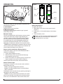
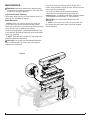
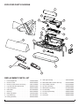
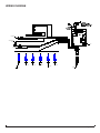
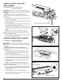
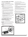
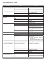
Service Manual
Model
DLGM29
Part Number
6908550000
IMPORTANT SAFETY INFORMATION: Always read this manual first before attempting to service this log grate. For your
safety, always comply with all warnings and safety instructions contained in this manual to prevent personal injury or property damage.
Dimplex North America Limited
1367 Industrial Road Cambridge ON Canada N1R 7G8
1-888-346-7539 www.dimplex.com
In keeping with our policy of continuous product development, we reserve the right to make changes without notice.
© 2013 Dimplex North America Limited
REV
PCN
DATE
00
-
30-AUG-12
01
-
6-Aug-13
7400620000R01
TABLE OF CONTENTS
OPERATION. . . . . . . . . . . . . . . . . . . . . . . . . . . . . . . . . . . . . . . . . . . . . . . . . . . . . . . . . 3
MAINTENANCE . . . . . . . . . . . . . . . . . . . . . . . . . . . . . . . . . . . . . . . . . . . . . . . . . . . . . . 4
EXPLODED PARTS DIAGRAM. . . . . . . . . . . . . . . . . . . . . . . . . . . . . . . . . . . . . . . . . . 5
REPLACEMENT PARTS LIST. . . . . . . . . . . . . . . . . . . . . . . . . . . . . . . . . . . . . . . . . . . 5
WIRING DIAGRAM. . . . . . . . . . . . . . . . . . . . . . . . . . . . . . . . . . . . . . . . . . . . . . . . . . . . 6
HEATER ASSEMBLY REPLACEMENT. . . . . . . . . . . . . . . . . . . . . . . . . . . . . . . . . . . . 7
LED LIGHT ASSEMBLY REPLACEMENT. . . . . . . . . . . . . . . . . . . . . . . . . . . . . . . . . . 8
FAN ASSEMBLY REPLACEMENT . . . . . . . . . . . . . . . . . . . . . . . . . . . . . . . . . . . . . . . 8
Fan Motor and Fan Housing. . . . . . . . . . . . . . . . . . . . . . . . . . . . . . . . . . . . . . . . . . . . . . . . . . . . . . . . 8
TROUBLESHOOTING GUIDE. . . . . . . . . . . . . . . . . . . . . . . . . . . . . . . . . . . . . . . . . . . 9
Always use a qualified technician or service agency to repair this log grate.
! NOTE: Procedures and techniques that are considered important enough to emphasize.
CAUTION: Procedures and techniques which, if not carefully followed, will result in damage to the equipment.
WARNING: Procedures and techniques which, if not carefully followed, will expose the user to the risk of fire, serious
injury, or death.
2www.dimplex.com
OPERATION
Figure 1
Figure 2
B
On
Button
Battery
A
Off
Button
Battery
Cover
The manual controls for the Log Grate are located in the
front right side. (Figure 1)
A. On/Off Switch
Supplies power to the Log Grate.
B. Momentary Button
Pressing this button toggles between Logs; Logs and
Flame Effect; and Off.
Remote Control
The unit is supplied with a radio frequency remote control.
This remote control has a range of approximately 50’
(15.25m). It does not have to be pointed at the fireplace
and can pass through most obstacles (including walls).
It is supplied with one of 243 independent frequencies
to prevent interference with other units. The frequency
designation is indicated on the back of the remote control.
! NOTE: Before attempting any operation with the remote
control, pull the plastic insulator strip out from between the
remote casing and battery cover (Figure 2).
back on to return to Level 1 - Logs and Light only operation.
Battery Replacement
To replace the battery:
1. Slide battery cover open on the remote control
(Figure 2).
2. Install one (1) 12-Volt (A23) battery in the battery
holder.
3. Close the battery cover.
Battery must be recycled or disposed of properly.
Check with your Local Authority or Retailer for
recycling advice in your area.
Remote Control Initialization/ Reprogramming
Follow these steps for remote control initialization and if
required, re-initialization:
1. Unplug power adapter from unit.
2. Wait a minimum of five (5) seconds and then plug
power adapter back into unit.
3. Within 10 seconds of re-acquiring power, press the ON
button located on the remote control. (Figure 2)
This will synchronize the remote control and receiver.
Remote Control Usage
Pressing the On button, on the remote control, switches
between the two levels:
Level 1: The logs and lights are turned on.
Level 2: The logs and lights remain on and the flame
effect is activated.
The fireplace can be turned off at any point by pressing the
Off button on the remote control.
! NOTE: Once the mist has been activated, the unit will
have to be turned Off, using either the momentary button,
on the unit, or the Off button on the remote control, then
3
MAINTENANCE
W
ARNING: Disconnect power before attempting any
maintenance or cleaning to reduce the risk of fire, electric shock or damage to persons.
Log Grate Surface Cleaning
Use a warm damp cloth only to clean surfaces of the Log
Grate. Do not use abrasive cleaners.
Water Reservoir
! NOTE: There is no need to remove any of the logs
or move the unit to access the water storage system.
However if you decide to move the unit to perform cleaning
ensure that the logs are stable before moving.
The water storage system is located behind the back log.
It can easily be removed by lifting each of the components
directly up. (Figure 3)
! NOTE: There are tabs, on each end, that need to be
turned to release the components.
CAUTION: It is strongly recommended that Distilled
water or softened water be used in the unit to prevent
scaling of the components.
If you do not intend on using the unit for longer than 2
weeks, empty and drain the unit of water, and dry all of the
water containing components.
It is recommended that all of the water containing
components are cleaned with soap and water on a
biweekly basis. A small brush has been included to assist
in cleaning difficult items/areas, i.e. the transducer.
CAUTION: Do not put plastic components in the
dishwasher.
! NOTE: If you need to move the unit ensure that all of
the components that contain water have been emptied
before relocating.
Figure 3
4www.dimplex.com
EXPLODED PARTS DIAGRAM
9
8
5
19
12
18
13
17
14
16
10
7
15
4
3
11
1
6
2
REPLACEMENT PARTS LIST
1. Power Adapter Set . . . . . . . . . . . . . . . . . . . . 2100220100RP
11. LED Light Assembly. . . . . . . . . . . . . . . . . . . . 3001100200RP
2. Remote Control . . . . . . . . . . . . . . . . . . . . . . . 3000370500RP
12. Removable Refill Container with Cap. . . . . . 0441440100RP
3. Remote Control Receiver & Housing . . . . . . .3001110100RP
13. Cap for Refill Container . . . . . . . . . . . . . . . . . 0441440300RP
4. Log Grate with Wire Harness Set. . . . . . . . . 6908540159RP
14. Top Cover Assembly. . . . . . . . . . . . . . . . . . . 9600530100RP
5. Log Set Assembly. . . . . . . . . . . . . . . . . . . . . 9600510100RP
15. Water Reservoir (Sump) . . . . . . . . . . . . . . . . 0441380100RP
6. Ember Bed . . . . . . . . . . . . . . . . . . . . . . . . . . 0441000300RP
16. Fan Assembly. . . . . . . . . . . . . . . . . . . . . . . . 5300300100RP
7. Back Log . . . . . . . . . . . . . . . . . . . . . . . . . . . . 0440740300RP
17. Fan Housing Assembly. . . . . . . . . . . . . . . . . 9600540100RP
8. Metal Light Shield. . . . . . . . . . . . . . . . . . . . . 1025340159RP
18. Fan Filter . . . . . . . . . . . . . . . . . . . . . . . . . . . . 8600300100RP
9. Light Shield Log. . . . . . . . . . . . . . . . . . . . . . . 0441260100RP
19. Transducer . . . . . . . . . . . . . . . . . . . . . . . . . . 3800040100RP
10. Heating Assembly. . . . . . . . . . . . . . . . . . . . . 9600520100RP
5
WIRING DIAGRAM
123
ELEMENT
TRANSDUCER
24 VDC
+
PCB
M
FAN
MOTOR
7 20 8 21
1234
1234
LOG #2
LOG #1
LOG #3
LOG #6
LOG #4
LOG #5
EMBERBED
6www.dimplex.com
REMOTE CONTROL RECEIVER
REPLACEMENT
Figure 4
Tools Required: Philips head screwdriver
Flat Head Screwdriver
WARNING: Disconnect power before attempting any
maintenance to reduce the risk of electric shock or damage
to persons.
! NOTE: Ensure that all of the components that
contain water have been emptied before performing any
maintenance.
1. Disconnect and remove all of the logs from the unit and
put them in a safe place.
2. Remove the two (2) screws around the Remote Control
Housing. (Figure 4)
3. Remove the housing being careful not to add any strain
to the wires connecting to the switches.
4. Transfer the wire connectors from the terminals on the
original board to the same location on the replacement
board.
! NOTE: Use a flat head screwdriver to gently pry
between the end of the connector and the remote control
receiver to release the wires.
5. Re-assemble the remainder of the log grate in reverse
order from the instructions above.
Remote Control Receiver Housing
Figure 5
HEATER ASSEMBLY REPLACEMENT
Tools Required: Philips head screwdriver
Flat Head Screwdriver
WARNING: Disconnect power before attempting any
maintenance to reduce the risk of electric shock or damage
to persons.
! NOTE: Ensure that all of the components that
contain water have been emptied before performing any
maintenance.
1. Disconnect and remove all of the logs from the unit,
including the light shield and associated log, and put
them in a safe place. (Figure 5)
2. Remove the removable refill container and set aside.
3. From the front remove the six (6) screws that hold the
heating and light assembly to the housing. (Figure 6)
4. Disconnect the two connections on either end of the
heater assembly.
! NOTE: Use a flat head screwdriver to gently pry
between the end of the connector and the remote control
receiver to release the wires.
5. Remove the two (2) screws that hold the LED assembly to the heater assembly and reinstall it onto the new
heater assembly.
6. Attach the wires onto the new heater assembly.
7. Re-assemble the remainder of the log grate in reverse
order from the instructions above.
Figure 6
Figure 7
Heater Assembly
LED Light Assembly
7
LED LIGHT ASSEMBLY REPLACEMENT
Tools Required: Philips head screwdriver
Flat Head Screwdriver
WARNING: Disconnect power before attempting any
maintenance to reduce the risk of electric shock or damage
to persons.
! NOTE: Ensure that all of the components that
contain water have been emptied before performing any
maintenance.
1. Disconnect and remove all of the logs from the unit,
including the light shield and associated log, and put
them in a safe place. (Figure 5)
2. Remove the removable refill container and set aside.
3. From the front remove the six (6) screws that hold the
heating and light assembly to the housing. (Figure 6)
4. Disconnect the wire connection on the LED light assembly.
5. On the new light assembly, attach the light lenses to
the board by orienting the lens so that it fits directly
onto the light, ensuring that the lines on the lens are
perpendicular to the heating element.
6. Remove the two (2) screws that hold the LED assembly
to the heater assembly and replace with the new LED
light assembly. (Figure 6)
7. Reattach the wire onto the new light assembly.
8. Re-assemble the remainder of the log grate in reverse
order from the instructions above.
them in a safe place. (Figure 5)
2. Disassemble the sump components. (Figure 3)
3. Remove the three (3) screws that hold the cover onto
the fan housing. (Figure 8)
4. Remove the fan motor out of the housing and disconnect the wiring connection located near the bottom of
the housing.
5. If replacing only the motor, attach new motor and reassemble the remainder of the log grate in revers order
from the instructions above.
• If replacing the housing, remove the three (3) screws
attaching the base to the log grate. (Figure 9)
6. Attach new fan housing base to the log grate.
7. Transfer the filter from the old housing to the new housing.
8. Reinstall the fan motor and reconnect the wire.
9. Re-assemble the remainder of the log grate in reverse
order from the instructions above.
Figure 9
FAN ASSEMBLY REPLACEMENT
Fan Motor and Fan Housing
Tools Required: Philips head screwdriver
Flat Head Screwdriver
WARNING: Disconnect power before attempting any
maintenance to reduce the risk of electric shock or damage
to persons.
! NOTE: Ensure that all of the components that
contain water have been emptied before performing any
maintenance.
1. Disconnect and remove all of the logs from the unit,
including the light shield and associated log, and put
Figure 8
Fan Motor
Fan Motor
8www.dimplex.com
TROUBLESHOOTING GUIDE
PROBLEM
CAUSE
SOLUTION
General
Unit turns on or off by itself
Power cord gets warm
Remote control has a similar frequency to
other remotes in the area.
Replace Remote Control. Initialize to Remote
Control Receiver.
Defective Remote Control Receiver
Replace Remote Control Receiver. Initialize to
Remote Control.
Normal Operation
The power cord may get slightly warm to the
touch when the heater is on
Defective power cord
Replace power cord if cord gets hot to the
touch.
Improper operation
Refer to Operation Section
No incoming power from the electrical wall
socket
Check Fuse/Breaker Panel
Power adapter set not connected properly
Refer to installation instructions for wiring
instructions.
Defective Remote Control Receiver
Replace Remote Control Receiver. Initialize
with Remote Control.
Improper operation
Refer to Operation Section
Remote control not initialized to log grate
Initialize the remote control
Remote Control not working
Install new battery into the Remote Control.
Reinitialize remote control where necessary
Appearance
Log grate does not turn on in
Manual Mode
Log grate does not turn on in
Remote Mode
Replace Remote Control Receiver where necessary. Initialize Remote Control Receiver to
Remote Control.
Defective Remote Control Receiver
Replace Remote Control Receiver. Initialize to
Remote Control
Loose connection
Check wiring connections
Defective Log Grate wiring
Replace Log Grate Assembly
Loose connection
Check wiring connections
Defective LED in Log
Connect log to another log grate connection to
verify if log works.
• If log works, wiring defective - Replace Log
Grate Assembly
• If log does not work, LED defective- replace
Logs
Loose connection
Check wiring connections
Defective Ember bed wiring
Replace Ember bed
Logs or Ember bed are still glowing after unit is turned off (with
remote or manual switches)
Defective Remote Control Receiver
Replace Remote Control Receiver
Mist is not coming out
Not enough water in the unit
Fill unit with water
Water in unit is too cold
Allow water to warm to room temperature.
If using distilled or reverse osmosis water, unit
will not produce a consistant mist
Add 1/8 tsp of table salt to water reservoir to
introduce electrolytes, only repeat when mist is
not being produced correctly
Cord is located over emitter on transducer
Relocate cord so that mist is free to rise off of
transducer.
Defective Transducer
Replace Transducer
The cord from the power board is not working
Ensure that the cord is not pinched.
All logs dim, not glowing
One Log dim, not glowing
Ember Bed dim, not glowing
Mist is not coming out and the red
light by the transducer is not on
Ensure that the cord is fully inserted into the
connection on the power board.
9
PROBLEM
CAUSE
SOLUTION
Mist is coming out fast
Filter is missing off of Fan Housing
Replace Fan Filter
Mist appears to be “falling”
Loose connection
Check heater wiring connections
Defective Heater
Replace Heating assembly
Unit is not level
Level unit
Log arrangement is blocking air flow
Rearrange logs
Light Lenses are not correctly oriented
Adjust Lenses
Light Lenses are not present
Replace light lenses
Mist does not appear to be coming out evenly
10www.dimplex.com