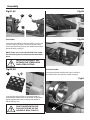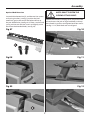
1
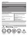
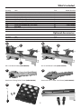
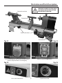
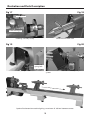
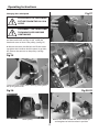
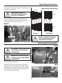
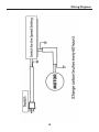
AXMINSTER Hobby Code 505020 Code 505021 SERIES AH-1218 & AH-1218VS Woodturning Lathes Index of Contents Index of Contents 02 Declaration of Conformity 02 What’s Included 03 General Instructions for 230V Machines 04 Specification05 Assembly05-06-07 Illustration and Parts Description 08-09-10 Operating Instructions 11-12-13 Removing the Faceplate 13 Removing Drive/Live Centres 14 Maintenance14 Parts Breakdown 15 Parts List 16-17-18 Wiring Diagram 19 Declaration of Conformity Copied from CE Certificate Manufactured by Laizhou Chunlin Machinery Co. is in compliance with the following standards or standardisation documents in accordance with Council Directives. The undersigned, Matthias Grzam authorised by Laizhou Chunlin Machinery Co., Ltd. No. 269 Baoshi Road Wenfeng Street 261400 P.R. China • 2006/42/EC Machinery Directive • 2004/108/EC EMC Directive (Electro Magnetic Compatibility) Model Number 1218A, 1218DA Wood Lathe • 2006/95/EC Low Voltage Directive • 2002/95/EC RoHS Directive (Reduction of Hazardous Substances) Please read the Instruction Manual prior to using your new machine; as well as the operating procedures for your new machine, there are numerous hints and tips to help you to use the machine safely and to maintain its efficiency and prolong its life. Keep this Instruction Manual readily accessible for any others who may also be required to use the machine. Warning Fully read manual and safety instructions before use Ear protection should be worn The symbols below advise that you follow the correct safety procedures when using this machine. Eye protection should be worn 2 Dust mask should be worn HAZARD Motor gets hot What’s Included Quantity Item Part 1 No 1 No 1 No 1 No 1 No 1 No 1 No 1 No 1 No 1 No AH-1218 Wood Lathe (Index Lock not fitted to the lathe) AH-1218VS Wood Lathe (Index Lock not fitted to the lathe) Banjo arm (fitted) 150mm Tool rest (fitted to banjo arm) 75mm Faceplate (fitted to headstock) Axminster 4 Prong Drive Centre (25mm) Axminster Standard 60˚ Live Centre Push Rod Tool Holder and two Phillips screws/washers Tailstock handle A B C D E F G H I J Model Number 1218A (505020) 1218DA (505021) (code 340106) (code 340203) Optional Accessories Quantity Item Part 1 No Bed Extension with Hex screws, washers K A B E (code 503035) D C AH-1218 Wood Lathe (code 505020) AH-1218VS Wood Lathe (code 505021) G F Axminster 4 Prong Drive Centre (code 340106) H Axminster Standard 60˚ Live Centre (code 340203) I K 3 General Instructions for 230V Machines Do not work with cutting tools of any description if you are tired, your attention is wandering or you are being subjected to distraction. A deep cut, a lost fingertip or worse; is not worth it! Above all, OBSERVE…. make sure you know what is happening around you, and USE YOUR COMMON SENSE. Work Place/Environment Make sure when the machine is placed that it sits firmly on the bench or stand, that it does not rock, that it is sufficiently clear of adjacent obstacles so that you have unimpeded access to all parts of the machine. The machine is designed for indoor use, do not use when or where it is liable to get wet. Keep the machine clean; it will enable you to more easily see any damage that may have occurred. Clean the overall machine with a damp soapy cloth if needs be, do not use any solvents or cleaners, as these may cause damage to any plastic parts or to the electrical components. Clean the machined components with a lightly oiled cloth. If the machine is liable to be standing idle for any length of time a light coat of machine or spray oil will minimise rusting. Specific Safety Instructions for Woodturning Lathes 1. Do not use ‘split’ work pieces. 2. Always start at the lowest speed when starting a new task. 3. Try to render a new work piece “round” (or as close as is practical) before turning. WARNING! KEEP TOOLS AND EQUIPMENT OUT OF THE REACH OF YOUNG CHILDREN 4. Check that the tool rest is at or slightly below the centre line of the work piece. 5. Check the work piece is securely mounted in the lathe before switching on the power. It is good practice to leave the machine unplugged until work is about to commence, also make sure to unplug the machine when it is not in use, or unattended. Always disconnect by pulling on the plug body and not the cable. Once you are ready to commence work, remove all tools used in the setting operations (if any) and place safely out of the way. Re-connect the machine. 6. Rotate the work piece by hand, to check that it is:- centralised, clear of the tool rest, not ‘split’ or has loose knots. 7. Where lathes have the facility to be reversed; check the machine is rotating in the correct direction. Carry out a final “tightness” check e.g. chuck or face plate, work piece, tool rest, etc., check that the correct speed has been selected. 8. If your lathe has the facility to run in reverse, you must ensure that the mounting accessories (chucks, faceplates etc.,) can be ‘locked’ onto the lathe mandrel, and in the case of chucks have some form of security device to prevent them ‘unwinding’ during reverse operation. Make sure you are comfortable before you start work, balanced, not reaching etc. If the work you are carrying out is liable to generate flying grit, dust or chips, wear the appropriate safety clothing, goggles, gloves, masks etc. If the work operation appears to be excessively noisy, wear ear-defenders. 9. Make sure your tools are stored/racked away from the turning area of the lathe. Do not reach over a rotating work piece at any time. If you wear your hair in a long style, wearing a cap, safety helmet, hairnet, even a sweatband, will minimise the possibility of your hair being caught up in the rotating parts of the tool, likewise, consideration should be given to the removal of rings and wristwatches, if these are liable to be a ‘snag’ hazard. Consideration should also be given to nonslip footwear, etc. 10. Do not ‘dig in’ or try to take too large a cut. 11. Do not leave the lathe running unattended; or leave the machine until everything is stopped. 12. If you are turning between centres with ‘softish stuff’, check and reposition the tailstock centre frequently. 4 Specification Model Code Rating Power Speed Spindle Taper Spindle Thread Taper Tailstock Distance Between Centres Max Diameter over Bed Tool Rest Stem Diameter Overall L x W x H Weight AH-1218 505020 Hobby 600W (230V) (5) 500-3,150 rpm MT2 1” x 8tpi (Ref T04M) 2MT 457mm 305mm 16mm 820 x 440 x 280mm 40kg Model AH-1218VS Code 505021 Rating Hobby Power 550W, 230V Speed (2) 500-2,040 and 1,000-4,080 Spindle Taper MT2 Spindle Thread 1” x 8tpi (Ref T04M) Taper Tailstock 2MT Distance Between Centres 457mm Max Diameter over Bed 305mm Tool Rest Stem Diameter 16mm Overall L x W x H 820 x 440 x 280mm Weight 40kg Assembly Please take some time to read the section entitled “Illustration & Parts Description” to identify the various parts of your machine so that you are familiar with the terminology we will use to enable you to set up and operate your table lathe safely and correctly. Please see figures A-B-C-D for fitting instructions for the indexing lock. Fig A-B-C-D The machine and its accessories will arrive coated with corrosion preventative grease. This will need to be cleaned from the machine, its components and accessories prior to it being set up. Use coal oil, paraffin or a proprietary de greaser to remove the barrier grease. Be warned, it will stain if you splash it on clothing etc., wear overalls, coverall et al., rubber gloves are also a good idea, as is eye protection if your cleaning process tends to be a little bit enthusiastic. Removing the plug After cleaning, lightly coat the machine with a thin layer of light machine oil. N.B If you used paraffin/ kerosene make sure you apply this thin film sooner rather than later. 95% of the machine comes fully assembled, all that remains is to fit the four prong drive centre (F) the 60˚ live centre (G) and the tool holder (I). Fitting the indexing lock Securely tighten Indexing Lock The indexing lock is know supplied separately in the accessory pack and not fitted to the lathe. We recommend to fit the index lock only if you plan to use the index facility in the future. NOTE: DO NOT USE THE INDEX LOCK AS A SPINDLE LOCK AS YOU WILL DAMAGE LOCKING PIN. Drive Centre/Faceplate Locate the four prong drive centre (F) and slide it through the centre of the faceplate into the headstock spindle (see fig 1). Locate the live centre (G) and slide it into the tailstock barrel (see fig 2). Continues Over... 5 Assembly Fig 01-02 Fig 05 F G Fig 06 Tool Holder Locate the tool holder (I) the two Phillips screws and washers. (see fig 3) Place a washer over the screws and screw them into the two pre-drilled holes below the headstock, (see fig 4). NOTE: There are also two pre-drilled holes under the tailstock if you wish to mount the tool holder there. NOTE GIVE ADEQUATE GAP BETWEEN THE SCREW HEAD AND LATHE CASTING! Fig 03-04 Tailstock Handle Locate the tailstock handle and screw it into the threaded hole in the tailstock wheel, see fig A. I Fig A Line up the machined slots in the tool holder (I) and slide the holder down over Phillips screws then lightly tighten the screws to clamp the holder in place, (see figs 5-6). DON’T OVERTIGHTEN THE PHILLIPS SCREWS AS THE HOLDER IS ONLY PLASTIC! J 6 Assembly Optional Bed Extension NOTE: DON’T TIGHTEN THE SCREWS AT THIS POINT! Locate the bed extension (K) and the two Hex screws and spring/washers, (see fig 7) position the bed extension against the end of the lathe and line up the pre-drilled holes, (see figs 8-9). Place a washer and spring washer over the Hex screws and lightly screw them into the threaded holes, (see fig 10). Release the tailstock clamping lever and position the tailstock across the join to align both beds, re clamp the tailstock in position and tighten both Hex screws. (see figs 11-12). Both beds are now aligned. Fig 07 Fig 10 K Hex screw Fig 08 Fig 11 Fig 09 Fig 12 K 7 Illustration and Parts Description AH-1218 Headstock cover Headstock Faceplate Tailstock 150mm Tool rest Lathe bed Carrying handle Lower pulley door lock NVR switch assembly Banjo arm Motor assembly Index lock pin AH-1218VS Rubber foot 4 Prong drive centre 60˚Live centre Tool rest lock Tailstock handle Motor handle lock Motor handle Push rod tool holder Banjo arm lock Start (ON) Stop (OFF) 8 Variable speed control Illustration and Parts Description WARNING! MAKE SURE THE INDEX LOCK PIN IS IN THE UP POSITION BEFORE SWITCHING ON. Tailstock barrel lock Tailstock lock Power cable hooks Tool holder Fig 13 Fig 14 (ON) ( I ) and (OFF) (O) buttons AH-1218 Emergency stop shroud, slap the shroud down to stop the lathe in an emergency Fig 15 Fig 16 AH-1218VS Control box 9 Speed control dial Illustration and Parts Description Fig 17 Fig 18 Index pointer Index locking pin Indexing assembly facility Tailstock barrel with scale Fig 19 Fig 20 Door knob spring lock Motor pulley access door Lower the headstock cover to reveal the pulley system Optional bed extension attached giving a maximum of 965mm between centres 10 Operating Instructions Indexing Facility The indexing facility is useful for fluted columns, clock faces and accurate hole positioning. Lift and Rotate the index locking pin knob to unlock the headstock spindle, turn the faceplate and line up one of the positions then lower the indexing pin to lock the spindle in position, (see figs 21-22-23-24). WARNING! DO NOT USE THE INDEX PIN WHEN REMOVING THE FACEPLATE OR CHUCK OTHERWISE THE PIN COULD BRAKE! Fig 21 Fig 22 Turn the faceplate to select the required position then lower the index pin knob to lock the spindle Fig 23 Fig 24 Indexing pin in the up position (spindle unlocked) Indexing pin in the locked down position 11 Operating Instructions Fig 27 Changing the Lathe Speed PLEASE NOTE THE FOLLOWING PICTURES SHOW THE AH-1218 LATHE. DISCONNECT THE LATHE FROM THE MAINS SUPPLY BEFORE CONTINUING! 1. Open the motor pulley access door by pulling the door knob back, (see figs 25-26). Lower the headstock cover to access the pulleys, (see fig 27). 2. Release the motor handle lock and lift the motor up, tighten the handle to lock the motor in position, this releases the tension on the pulleys (see figs 28-29). Fig 25 Open the motor pulley access door by pulling back the sprung door knob. Fig 28-29 Fig 26 Motor pulley Release the motor handle lock, lift the motor up and retighten to lock the motor in position 12 Operating Instructions 3. Reposition the belt to one of the five positions on the pulleys, (see figs 30). Lathe Pulley Speed Chart Spindle MAKE SURE THE BELT IS INSERTED CORRECTLY INTO THE PULLEY GROOVES! Fig 30 4080 rpm 1000rpm 2400 rpm 500 rpm 3150 rpm 2000 rpm 1430 rpm 500 rpm 4. Lower the motor to put tension back on the pulleys and lock in position. Raise the headstock cover and close the motor access door. 1000 rpm Spindle Motor Motor Low AH-1218 Pulley grooves High AH-1218VS NOTE: The speed chart above shows approximate speeds with the lathe off load. Removing the Faceplate Fig A DISCONNECT THE LATHE FROM THE MAINS SUPPLY BEFORE CONTINUING! b MAKESURE THE LOCKING PIN IS IN THE UP POSITION BEFORE CONTINUING! a You will require two spanners. Fig B Place the first spanner onto the lathe spindle (a) and the other on the faceplate (b), see fig A. While holding the first spanner in position, turn the other anti-clockwise (remember left handed thread) and remove the faceplate, see fig B. 13 Removing Drive/Live Centres To remove the Drive Centre (F), locate the push rod (H), while holding the Drive Centre insert the push rod (H) through the centre hole of the headstock wheel and push the Drive Centre (F) out (see fig 31). Repeat the procedure for the Live Centre (G) in the tailstock (see fig 32). Fig 31 Fig 32 G H H F Maintenance Daily after use Monthly • Clean wood shavings away from the lathe bed and tool rest. •Check the tension of the belt and adjust if required, (See Changing the Belt Speed). Also check the condition of the belt for signs of wear and change if required, (contact our technical department on 03332 406406) • Spray a light coat of Camellia Oil or Axcaliber Dry Lubricant, (see our cataloge for details) over the lathe bed, to allow the Banjo and Tailstock to run more smoothly over the bed, also spray the headstock and tailstock to prevent corrosion. •Check any build up of wood shaving on the motor and spindle pulleys and clean if necessary. • Using an airline, blow out the motor’s air vent. • Also blow out the air vents on top of the control box for the variable speed lathe (AH-1218VS). Note: If the lathe is not going to be used for a period of time, spray a light coat of oil over the bed and place a dust sheet over the lathe. 14 Parts Breakdown 15 Parts List 1218VDA (AH-1218VS) No. 1 Description Washer ø4 Qty No. Description 7 36 Bush Qty 1 2 Semi-circle head screwM4X8 2 37 Lock handle for tool rest base 1 3 Hex socket screw M6×12 3 38 Headstock spur center 1 4 Hand wheel 1 39 Face plate 1 5 Semi-circle head screwM6×24 6 40 Gear 1 6 Semi-circle head screwM4X6 2 41 Round plate 1 7 Hinge 1 42 Headstock spindle 1 8 Hex nut M6 3 47 Washer 1 9 Side protection guard 1 48 Semi-circle head screw M3×12 1 10 Lock piece 1 51 Handling hand 2 11 Cam follower tailstock 1 52 Clip 4 12 Main shaft sleeve 1 54 The box cover 1 13 Ball bearing 80105 2 57 Pin hinge 1 14 Retaining ring 47 2 58 Mounting plate 1 15 shaft 1 59 Ball 1 16 Cap 1 60 Knock-out rod 1 17 Screw 1 61 Hinge 2 18 Bush 1 62 Door latch 1 19 Spring 1 63 Drive belt 1 20 Index pin 1 64 Connecting rod 1 21 Hex socket screw M8×30 4 65 Spring t 1 22 Spring washer 4 66 Washer 1 23 Washer ø8 4 67 The main body 1 24 Nut M10 1 68 Motor pulley 1 25 Indicator 1 69 Hex socket screw M6×16 3 26 Hex socket screw M6×12 1 70 Spring washer 3 28 Tool rest 1 71 Washer ø6 3 29 Retaining ring 10 1 72 Motor plate with notch 1 30 Tool rest cam follower 1 73 Tapping screw 1 31 Bolt 1 74 Moto 1 32 Spring 1 75 Switch 1 33 Handle 1 76 Box plate 1 34 Lock bolt 1 77 Tapping screw 4 35 Tool rest bas 1 78 Plug line 1 16 Parts List No. Description Qty No. Description Qty 79 Switch-box 1 97 Retaining ring 10 1 80 Strain relief 1 98 Tailstock 1 81 Strain relief 2 99 Tailstock quill 1 82 Cable 1 100 Semi-circle head screw M5×12 2 83 Hex socket screw M10×25 2 101 Tailstock axis 1 84 Washer ø10 2 102 Tool rack 2 103 Cup center 1 86 Lock nut 2 104 Ball bearing 1 87 Nut M10 1 105 Taper rod 1 88 Rubber washer 6 106 Bed 1 89 Support 1 107 Nut M10 1 90 Semi-circle head screw M5×12 4 108 Hex socket screw M8×16 1 91 Washer ø5 2 109 Semi-circle head screw M4×20 3 92 Screw 1 110 Cam follower tailstock 1 93 Bush 1 111 Motor pulley 1 94 Quill adjusting wheel 1 114 Extension bed 1 95 Eccentric axis 1 115 Small plate 1 96 Cam follower tailstock 1 116 Variable plate 1 1218A (AH-1218) No. Qty No. Description 1 Description Washer ø4 7 14 Retaining ring 47 2 2 Semi-circle head screwM4X8 2 15 Shaft 1 3 Hex socket screw M6×12 3 16 Cap 1 4 Hand wheel 1 17 Screw 1 5 Semi-circle head screwM6×24 6 18 Bush 1 6 Semi-circle head screwM4X6 2 19 Spring 1 7 Hinge 1 20 Index pin 1 8 Hex nut M6 3 21 Hex socket screw M8×30 4 9 Side protection guard 1 22 Spring washer 4 10 Lock piece 1 23 Washer ø8 4 11 Cam follower tailstock 1 24 Nut M10 1 12 Main shaft sleeve 1 25 Indicator 1 13 Ball bearing 80105 2 26 Hex socket screw M6×12 1 17 Qty Parts List No. Description Qty No. Description Qty 28 Tool rest 1 74 Moto 1 29 Retaining ring 10 1 82 Cable 1 30 Tool rest cam follower 1 83 Hex socket screw M10×25 2 31 Bolt 1 84 Washer ø10 2 86 Lock nut 2 32 Spring 1 33 Handle 1 34 Lock bolt 1 87 Nut M10 1 35 Tool rest bas 1 88 Rubber washer 6 36 Bush 1 89 Support 1 37 Lock handle for tool rest base 1 90 Semi-circle head screw M5×12 4 38 Headstock spur center 1 91 Washer ø5 2 39 Face plate 1 92 Screw 1 42 Headstock spindle 1 93 Bush 1 51 Handling hand 1 94 Quill adjusting wheel 1 52 Clip 1 95 Eccentric axis 1 54 The box cover 1 96 Cam follower tailstock 1 57 Pin hinge 1 97 Retaining ring 10 1 58 Mounting plate 1 98 Tailstock 1 59 Ball 1 99 Tailstock quill 1 60 Knock-out rod 1 100 Semi-circle head screw M5×12 2 61 Hinge 2 101 Tailstock axis 1 62 Door latch 1 102 Tool rack 2 63 Drive belt 1 103 Cup center 1 64 Connecting rod 1 104 Ball bearing 1 65 Spring t 1 105 Taper rod 1 66 Washer 1 106 Bed 1 67 The main body 1 107 Nut M10 1 68 Motor pulley 1 108 Hex socket screw M8×16 1 69 Hex socket screw M6×16 3 109 Semi-circle head screw M4×20 3 70 Spring washer 3 110 Cam follower tailstock 1 71 Washer ø6 3 111 Motor pulley 1 72 Motor plate with notch 1 112 Switch panel 1 73 Tapping screw 1 113 Semi-circle head screw M4×14 2 114 Extension bed 1 115 Small plate 1 18 Wiring Diagram 19 The Axminster guarantee is available on Hobby, Trade, Industrial, Engineer, Air Tool & Axcnc Technology Series machines It’s probably the most comprehensive FREE guarantee ever- buy with confidence from Axminster! So sure are we of the quality, we cover all parts and labour free of charge for three years! • Look for the icon and put your trust in Axminster • No registration necessary - just keep your proof of purchase • Optional Service Plan for Industrial Series machinery Great value & easy-to-use, perfect for use at home Solid, reliable machines designed for daily use Top performers with class leading features and build quality for use in busy workshops Quality, precision machines for the workshop or education Small machines for the home engineer Compressors and tools for home or workshop use; durable and great value Free Three Year Guarantee on Axminster Hobby, Trade and Industrial Series woodworking and engineering machines, Axminster Air compressors and Air Tools, and bench top grinders - no registration necessary just proof of purchase. We will repair or replace at our discretion and will collect only from a UK mainland address, irrespective of the original delivery address. The Guarantee assumes that you have bought the correct machine for the required operation, in accordance with our guidelines; have operated and maintained it in accordance with the instruction manual; and that all cutting machines will be used with a blade which is sharp and serviceable at all times. It does not cover consumable items purchased with the original product, including original blades or abrasives. Precision CNC machines for industry and education Normal wear and tear; misuse, abuse and neglect are excluded and the machine should not have been modified in any way. Please do not attempt to service the product without first contacting us; we are happy to guide you but failure to do so may invalidate the guarantee. The Guarantee is transferable from owner to owner in the first three years but you must have original proof of purchase. Should we need to replace a machine in the first three years the guarantee will still continue to be effective from the original purchase date. Full Terms and Conditions can be found at axminster.co.uk/terms This guarantee does not affect your statutory rights. For more information visit axminster.co.uk/3years Please dispose of packaging for the product in a responsible manner. It is suitable for recycling. Help to protect the environment, take the packaging to the local recycling centre and place into the appropriate recycling bin. Only for EU countries Do not dispose of electric tools together with household waste material. In observance of European Directive 2002/96/EC on waste electrical and electronic equipment and its implementation in accordance with national law, electric tools that have reached the end of their life must be collected separately and returned to an environmentally compatible recycling facility. Axminster Tools & Machinery Ltd Weycroft Avenue, Axminster, Devon EX13 5PH axminster.co.uk