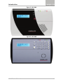
1
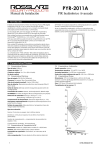
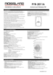
2012 December HLX-40/40A/40B Advanced Wireless Security Panel User Manual Copyright © 2012 by Rosslare. All rights reserved. This manual and the information contained herein are proprietary to REL, RSP Inc. and/or their related companies and/or subsidiaries’ (hereafter:”ROSSLARE”). Only ROSSLARE and its customers have the right to use the information. No part of this manual may be re-produced or transmitted in any form or by any means, electronic or mechanical, for any purpose, without the express written permission of ROSSLARE. ROSSLARE owns patents and patent applications, trademarks, copyrights, or other intellectual property rights covering the subject matter in this manual. TEXTS, IMAGES, AND ILLUSTRATIONS INCLUDING THEIR ARRANGEMENT IN THIS DOCUMENT ARE SUBJECT TO THE PROTECTION OF COPYRIGHT LAWS AND OTHER LEGAL RIGHTS WORLDWIDE. THEIR USE, REPRODUCTION, AND TRANSMITTAL TO THIRD PARTIES WITHOUT EXPRESS WRITTEN PERMISSION MAY RESULT IN LEGAL PROCEEDINGS. The furnishing of this manual to any party does not give that party or any third party any license to these patents, trademarks, copyrights or other intellectual property rights, except as expressly provided in any written agreement of ROSSLARE. ROSSLARE reserves the right to revise and change this document at any time, without being obliged to announce such revisions or changes beforehand or after the fact. Table of Contents Table of Contents 1. Introduction ....................................................................... 8 2. Operating the HLX-40 ..................................................... 10 2.1 Quick Reference ............................................................................... 10 2.2 About Everyday Operation ................................................................ 10 2.3 Arming Options ................................................................................ 10 2.3.1 Arm Away ................................................................................................. 10 2.3.2 Arm Home ................................................................................................ 11 2.3.3 Disarmed .................................................................................................. 11 2.3.4 Quick Arming ............................................................................................ 11 2.3.5 Instant Arming .......................................................................................... 11 2.3.6 Forced Arming .......................................................................................... 12 2.4 Entry/Exit Delay Options .................................................................... 12 2.4.1 Entry Delay ................................................................................................ 12 2.4.2 Exit Delay .................................................................................................. 12 3. Technical Specifications ................................................. 13 4. System Overview ............................................................ 15 4.1 HomeLogiX™ HLX-40 Wireless Panel ................................................ 15 4.2 The LCD Display................................................................................ 16 4.3 The Keypad ...................................................................................... 18 4.4 Sound Indicators ............................................................................... 20 4.5 LED Indicators ................................................................................... 21 5. User Menu Structure ....................................................... 22 6. Interactive Voice Response Menu ................................. 24 6.1 General ............................................................................................ 24 6.2 Arming Submenu ............................................................................. 25 6.3 Automation Submenu ...................................................................... 25 6.4 Voice Operation Submenu ................................................................ 25 6.5 Status Report .................................................................................... 26 HLX-40 User Manual iii Table of Contents 7. Reading the Event Log ................................................... 27 8. SMS Commands ............................................................... 28 9. User Menu Options ......................................................... 29 9.1 Accessing the User Menu .................................................................. 29 9.2 Changing the Master Code ............................................................... 29 9.3 Defining User Codes ......................................................................... 29 9.4 Authorization Codes ......................................................................... 30 9.5 Setting Date and Time ...................................................................... 30 9.6 Defining Date and Time Format ........................................................ 30 9.7 Setting Zone Bypass .......................................................................... 31 9.7.1 Enabling Zone Bypass ................................................................................ 31 9.7.2 Defining Bypass Zones ............................................................................... 31 9.8 Enrolling a Remote Control ............................................................... 32 9.9 Deleting a Remote Control................................................................ 32 9.10 Setting Phone Numbers .................................................................... 33 9.11 Activating/Deactivating PC Mode ...................................................... 33 10. Maintenance .................................................................... 34 10.1 Dismounting the Control Panel ......................................................... 34 10.2 Replacing the Backup Battery ............................................................ 34 A. Declaration of Conformity ............................................. 35 B. Limited Warranty ............................................................ 36 iv HLX-40 User Manual List of Figures List of Figures Figure 1: HLX-40 ............................................................................................ 8 Figure 2: HLX-40A.......................................................................................... 9 Figure 3: HLX-40B .......................................................................................... 9 Figure 4: Wireless Panel Components ........................................................... 15 Figure 5: The Keypad.................................................................................... 18 Figure 6: Replacing the Backup Battery ......................................................... 34 HLX-40 User Manual v List of Tables List of Tables Table 1: Quick Reference to Keypad Buttons................................................. 10 Table 2: HomeLogiX™ HLX-40 Wireless Panel .............................................. 16 Table 3: Display Options ............................................................................... 17 Table 4: Keypad Functions ............................................................................ 18 Table 5: Sound Indicators ............................................................................. 20 Table 6: LED Indicators ................................................................................. 21 Table 7: User Menu Options ......................................................................... 22 Table 8: SMS Commands ............................................................................. 28 vi HLX-40 User Manual Notice and Disclaimer Notice and Disclaimer This manual’s sole purpose is to assist installers and/or users in the safe and efficient installation and usage of the system and/or product, and/or software described herein. Before attempting to install and/or use the system, the installer and the user must read this manual and become familiar with all safety requirements and operating procedures. The system must not be used for purposes other than those for which it was designed. The use of the software associated with the system and/or product, if applicable, is subject to the terms of the license provided as part of the purchase documents. ROSSLARE ENTERPRISES LIMITED and/or its related companies and/or subsidiaries’ (hereafter:"ROSSLARE") exclusive warranty and liability is limited to the warranty and liability statement provided in an appendix at the end of this document. This manual describes the maximum configuration of the system with the maximum number of functions, including future options. Therefore, not all functions described in this manual may be available in the specific system and/or product configuration you purchased. Incorrect operation or installation, or failure of the user to effectively maintain the system, relieves the manufacturer (and seller) from all or any responsibility for consequent noncompliance, damage, or injury. The text, images and graphics contained in the manual are for the purpose of illustration and reference only. In no event shall manufacturer be liable for any special, direct, indirect, incidental, consequential, exemplary or punitive damages (including, without limitation, any and all damages from business interruption, loss of profits or revenue, cost of capital or loss of use of any property or capital or injury). All graphics in this manual are for reference only, some deviation between the image(s) and the actual product may occur. All wiring diagrams are intended for reference only, the photograph or graphic of the PCB(s) are intended for clearer illustration and understanding of the product and may differ from the actual PCB(s). HLX-40 User Manual vii Introduction 1. Introduction The HomeLogiX™ HLX-40 family of panels by Rosslare is the perfect wireless security system for intrusion protection of the home, or small office providing security monitoring and IVR Voice messaging. Users receive the latest RF technology in a wide selection of advanced wireless sensors and remotes, and benefit from smooth and easy operation of a large number of security and communication options. The panel has two full split reporting features for communicating to central station for Contact ID + 2-Way Voice Enabled event reporting and vocal communications. IVR features include Voice Assist, where the panel uses voice to prompt the user, Private Messaging to three destinations, with an optional 2-way voice session for every message. The HomeLogiX™ HLX-40 family comes in three attractive designs: HLX-40 HLX-40A HLX-40B Figure 1: HLX-40 8 HLX-40 User Manual Introduction Figure 2: HLX-40A Figure 3: HLX-40B HLX-40 User Manual 9 Operating the HLX-40 2. Operating the HLX-40 This chapter describes the day to day operation of the system, as well as provides a quick reference for the Arming/Disarming buttons in the system. 2.1 Quick Reference Use the following buttons on the keypad for quick arming the system: Table 1: Quick Reference to Keypad Buttons AWAY Arms all sensors and detectors for use when there is no one at home/office. HOME Arms all perimeter sensors and detectors as defined by the installer. For use when home/office is occupied. Disarms all armed sensors and detectors. DISARM QUICK Ignore an entry or move one level up in a menu ESC arms the system. For more on the keys and their function, see Section 4.3. 2.2 About Everyday Operation The HLX-40 system allows you to ensure the security of your home, both while you are home and while you are away. The system allows you to control attached sub-systems and appliances such as garage doors, lights, heating, and air conditioner via an expandable PGM output. 2.3 Arming Options The following sub-section describes the arming options available to the Installer. 2.3.1 Arm Away ARM AWAY is the full arming of the system, best used when there is no one is at home or in the office. In Away mode, the system enters Alarm mode if there is a zone violation, regardless of perimeter or interior type. To arm the sy stem using AWAY: 1. Verify that the system is ready for arming. 2. Press the AWAY arming key. 3. Enter your user code. 10 HLX-40 User Manual Operating the HLX-40 2.3.2 Arm Home Home arming is an arming of all perimeter sensors and detectors as defined by the installer. This is intended for when home or office is occupied. To arm the sy stem using HOME: 1. Verify that the system is ready for arming. 2. Press the HOME arming key. 3. Enter your user code. 2.3.3 Disarmed When disarmed, the HLX-40 system enters Alarm mode for each 24-hour zone. Alarms trigger only for panic, emergency, fire, 24-hour audible, and silent conditions. In this state, the system continuously checks zone status and holds the Ready status parameter. This parameter determines whether the system is ready to arm. The system becomes Ready to Arm when zones are either closed or bypassed, or Force Arming is enabled. To disarm the sy stem: 1. Press the Disarm key. 2. Enter your user code. 2.3.4 Quick Arming Quick arming allows arming the system without code entry. If Quick Arming is enabled (by the Installer during setup), a long press on one of the arming buttons activates Quick Arming. 2.3.5 Instant Arming If Instant Arming mode is enabled (by the Installer during configuration), the system skips the exit delay, cancels the entry delay configured, and initiates the alarm, which instantly causes an alarm to go off upon violation of any zone. When EN-CENELEC standard is enabled, only the Master user can use this feature. To instantly arm the sy stem: 1. Verify that the system is ready for arming. 2. Press either the HOME or the AWAY arming key. 3. 4. Enter your user code. Press the same arming key once again. (If EN-CENELEC standard is enabled, enter your Master user code once again). HLX-40 User Manual 11 Operating the HLX-40 2.3.6 Forced Arming If Forced Arming is enabled, the system is able to arm even when zones are in violation (open) but not defined as bypassed. In such a case, the system arms, effectively bypassing the open zone. Once the open zone is closed, the system completes arming, adding the previously bypassed zone to the monitored zones. 2.4 Entry/Exit Delay Options Entry and Exit actions delay the alarm mode and allow the system to ignore zone violations, as described below. 2.4.1 Entry Delay Entry delay allows the user a grace period for the time it takes to open the door and reach the keypad to disarm the system. If a zone of type Delay is violated while the system is armed (except Instant Arming), the system does not enter Alarm mode during the Entry Delay period setting. If the delay has transpired and the system still has not been disarmed, the system enters Alarm mode. During Entry Delay, the system signals the keypads to sound warning beeps at two rates: slower rate at first and faster rate during the last 10 seconds of the delay period. 2.4.2 Exit Delay Exit delay allows the user a grace period for the time it takes to reach the door from the keypad when arming the system upon exit. When arming a panel, the system ignores zone violations of the predefined delay zones during the Exit Delay period. Once the delay has transpired, the system enters Armed mode. During Home arming, the system ignores all interior zones as well as the predefined delay zones. The system may be disarmed during the Exit Delay period. During Exit Delay, the system emits warning beeps at two rates: slower rate at first followed by a faster rate of beeping during the last 10 seconds of the delay period. 12 HLX-40 User Manual Technical Specifications 3. Technical Specifications Electrical Characteristics External Power Supply 220 VAC/50 Hz, 110 VAC/60 Hz Operating Voltage Range 15 VDC, 800 mA Input Current Standby: 120 mA Max: 500 mA (750 mA w/GSM expansion) Internal Backup Battery 800 mAh for 6 hours standby Auxiliary Power Output 13.8 VDC, 500 mA max Display Two Line, 16 characters, white backlit LCD PGM Open Collector Outputs Two fully programmable, 200 mA, PTC protected External Siren Output 1 A relay Local Siren 80 dBA Communication (RF) Characteristics Frequencies 433.92 MHz (G version) 868.35 MHz (H version) RF Jamming Detection UL/EN selectable Anti-collision Proprietary RF protocol Programmable No-activity Timer 1–30 hours, per zone Reporting Three private telephone numbers. Two-Way Voice Communication Three private telephone numbers Telephone and Modem Built in dialer & 2400 Baud modem Environmental Characteristics Operating Temp. Range 32ºF – 140ºF (0ºC – 60ºC) without battery 32ºF – 113ºF (0ºC – 45ºC) with battery Storage Temp. Range -13ºF – 158ºF (-25ºC – 70ºC) Operating Humidity 0– 85% at 30ºC non-condensing Dimensions HLX-40 HLX-40A HLX-40B Height x Width x Depth 217 x 144 x 48 mm 217 x 144 x 50 mm (8.54 x 5.67 x 1.89 (8.54 x 5.67 x 1.97 in.) in. 217 x 144 x 48 mm (8.54 x 5.67 x 1.89 in.) Weight 520g (1.15 lb) 548g (1.21 lb) HLX-40 User Manual 530g (1.17 lb) 13 Technical Specifications In addition, the HLX-40 system complies with the following standards: CE FCC EN 50131-3 EN 50131-6 EN 50130-5 EN 50130-4 EN 60950-1 EN 50131-5-3 Security Grade 2 Environmental II 14 HLX-40 User Manual System Overview 4. System Overview The main components of the HomeLogiX™ HLX-40 wireless panel are: HomeLogiX™ HLX-40 Wireless Panel The LCD Display The Keypad Sound Indicators LED Indicators 4.1 HomeLogiX™ HLX-40 Wireless Panel The following figure presents the components of the wireless panel. Figure 4: Wireless Panel Components Power Indicator Menu Display Status Indicator Enter Keypad Door HLX-40 and HLX-40A Local Emergency Button HLX-40 User Manual Local sounder Microphone 15 System Overview Table 2 describes the components in the panel: Table 2: HomeLogiX™ HLX-40 Wireless Panel Menu Use to navigate between menus Power indicator Power LED Green on: system is ON Green flashing: AC power failure Status indicator Status LED Red on: system armed Red off: system disarmed Flash: entry and exit delay (according to beep rate) Keypad door Open to access the keypad buttons Local sounder System speaker Microphone Enables recording voice messages Local emergency button Keep pressed for 3 seconds to sound a standard panic alarm Display LCD display Enter Accept an entry or selection Panic Alarm is followed by a report to the Central Station and audible siren as defined by the Installer. 4.2 The LCD Display The LCD display clearly shows the system status. The display consists of two rows. The bottom line is divided into two and displays the system status and events. When in Idle mode, the first line displays the system's name (HomeLogiX™ by default) while the second line shows the system status. For example, the second line displays Ready. Pressing # (pound key), toggles the first line display between the System name display and the Time & Date display. The system status is displayed on the left of the bottom line. The events are displayed on the right of the system status. If there is more than one event, the event display toggles every two seconds. There are several display options as described in Table 3: 16 HLX-40 User Manual System Overview Table 3: Display Options System Status Ready Indicates that the system is ready for arming. Not ready Indicates that the system is not ready and that there are active zones. Press Enter to see which zones are active. If there is more than one active zone, pressing Enter or Menu displays the next open zone. When there are no more active zones, the display returns to the idle view. You can also exit the active zone view by pressing the ESC, Away or Home buttons. Event Display TRBL Indicates that a problem exists on the system. The following System Troubles may appear in the TRBL message: • Battery Missing • • • Dead Battery Low battery Power failure (AC Fail) • • • RF jamming Line Fail Communication Fail • Tamper In addition the following Zone Troubles may appear in the TRBL message: • Tamper • • • Low battery Short Wire Supervision (failure) MEM Indicates an alarm in memory MSG Indicates that a personal message is waiting HLX-40 User Manual 17 System Overview 4.3 The Keypad The keypad is used to program the wireless panel and to arm and disarm the sensors. Figure 5: The Keypad Table 4 describes the keypad functions: Table 4: Keypad Functions Key Press to Menu Navigate between User and Installer menus, and Normal mode. Navigate to the next menu or the next option within a menu. Enter Accept an entry or selection when in the menu. Displays the panel current status when in standby. Local Emergency When pressed for 3 seconds, a standard panic alarm Sounds AWAY Arm all sensors and detectors. Use this function when there is no one in the home/office. You must enter a user or master code. HOME Arm all perimeter sensors and detectors as defined by the Installer. Use this function when the home/office is occupied. You must enter a user or master code. 18 HLX-40 User Manual System Overview Key Press to DISARM Disarm all armed sensors and detectors. You must enter a user or master code. If the duress code is enabled by the Installer, entering the duress code when disarming sends a duress event to the Central Station and Private Phone. The system is locked out for 90 seconds in the event of 5 failed attempts to disarm the system. QUICK Ignore an entry (escape) or to move one level up in a menu. 0 Normal mode only Memory Display Press once to display the alarms caused during the last arming period per zone. The first line of the displays shows the alarm memory and the second line shows the zone description, event and time. Press Enter to toggle view between zone description and the Time & Date. Press Menu to display the next event. Press Esc to exit. You can also use 0 to insert a space when typing an entry. Note: When EN-CENELEC standard is enabled, only the Master user can access the memory display. 1 Normal mode only PGM ON – If enabled by Installer. Press once to enter PGM activation mode. The PGM status is indicated on the right. Press 1 to activate PGM 1 and/or 2 to activate PGM 2. 2 Normal mode only PGM OFF – if enabled by Installer. Press once to enter PGM deactivation mode. The PGM status is indicated on the right. Press 1 to deactivate PGM 1 and/or 2 to deactivate PGM 2. 3 Normal mode only Chime ON/OFF Manually toggle the chime on and off (if enabled by the installer) The default is off. 4 Normal mode only Volume Manually Adjust the system’s volume level. 5 Normal mode only Sound ON/OFF – If enabled by Installer. Manually toggle voice messages, keypad tone, and other sounds on and off (except for trouble beeps, forced arming, enrollment and RF test of wireless devices which is always on). 6 Normal mode only Bypass – If enabled by installer. Enter the last User menu Bypass option to arm the system by bypassing active zones. You must enter a user or master code. HLX-40 User Manual 19 System Overview Key Press to 7 Normal mode only Record User Message Record a voice message of up to fifteen seconds. Press and hold the 7 key for three seconds to erase a message. 8 Normal mode only Event Log Display Press once and your Master user code to display the event log. The first line of the display shows the event log (for example Burglar Alarm). The second line shows the zone description or system. Press Enter to toggle view between zone description and the Time & Date. Press Menu to display the next event. Press Esc to exit. 9 Normal mode only Play User Message Listen to voice messages. 4.4 Sound Indicators Table 5 describes the sounds are emitted by the system and keypad: Table 5: Sound Indicators Sound Sounded When Single beep A key is pressed Long Beep Illegal key entry Three short beeps An entry is successfully accepted. Four short beeps a minute If enabled, on trouble condition. Short beep every second An exit/entry delay is activated. (Beep sounded every 0.5 seconds during last 10 seconds of delay. Chime 1 & 2 Two (2) various chime sounds, when feature is activated Chime 3 Vocal announcement of “Zone Name” + Open Aside from the indication sounds, the system also has a voice confirmation of various events. This table does not include actual alarm sounds. Note that the audible indication of a fire zone differs from that of a normal intrusion zone. 20 HLX-40 User Manual System Overview 4.5 LED Indicators Table 6 describes the LED indicators of the power and status indicators Table 6: LED Indicators LED Behavior Power LED Green On when the system is ON. FLASHING when there is an AC power failure. Status LED Red OFF when system is disarmed ON when system is armed. FLASHING during entry/exit delay, according to the beep rate specified. HLX-40 User Manual 21 User Menu Structure 5. User Menu Structure The User menu enables configuring the basic user settings, such as setting the date and time and changing user codes. You can define one Master user and up to twenty additional users, each with an individual code. Settings marked with an “M” can be accessed by the Master user only, and appear only if the master code is entered. If the master code has not been specified and the installer has set the zone bypass to Off, the User menu is unavailable to regular users. To enter the User menu: 1. On the panel, press Menu repeatedly until the screen displays User. 2. Press Enter. 3. Enter the Master user code (the default code is 1234) and press Enter. The system is locked out for 90 seconds after entering 5 wrong codes. The User menu options are displayed in Table 7: Table 7: User Menu Options Select To (M) Edit Master Code Change the master code (see Section 9.2). (M) User Codes Specify user codes 1 through 20. If the user code exists, you can edit the code or delete it by pressing # (see Section 9.3). Authorization Code Specify the code that is used to configure the system’s settings with the remote programming software HR-P02. The default code is 1234. (M) Set Date & Time Set the Time & Date, as specified in Section 9.5. (M) Date & Time Format Specify the format in which the time is specified: 24 hour format or AM/PM. By toggling between the two using the Menu button. Specify the format in which the date is specified: DD-MM-YY or MM-DD-YY (see Section 9.6) Zone Bypass Enables you to arm the system by bypassing/un-bypassing selected zones (see Section 9.7). This option is enabled if manual bypass has been enabled by the installer. Note: 22 Zone bypass can be triggered only if the zone was enrolled. HLX-40 User Manual User Menu Structure Select To Remote Controls Enroll remote controls for quick activation of the system (see Section 9.8) (M) Private Numbers Specify up to three private telephone numbers (see Section 9.10). (M) PC Mode Enable or disable PC connection and activity when GSM expansion is installed. Otherwise PC mode is enabled Automatically (see Section 9.11). HLX-40 User Manual 23 Interactive Voice Response Menu 6. Interactive Voice Response Menu 6.1 General IVR (Interactive Voice Response) features include Voice Assist, where the panel uses voice to prompt the user. Either the system or a remote private telephone can initiate an IVR session. IVR session Initiated by a Remote Telephone User: The remote telephone user initiates an IVR session by calling the system’s number. The system answers after a preset number of rings. Press * to initiate connection. The system broadcasts the site description and waits for a code. The remote user must enter a valid master code to start a session. IVR session initiated by the System: The system initiates a session (if enabled by the Installer) upon an event occurrence. The system calls the private number and asks that you to press * to initiate the connection after which the system broadcasts the site and the event description. The user must then enter a valid master code to enter the IVR menu. The system hangs up after approximately 60 seconds of inactivity. If there is no answer from a private phone or if the user disconnects by pressing 9, the system switches to the next private number. The system retries calling the programmed private phones for a pre-programmed number of attempts unless the user disconnects the call session by pressing 9, in which case the session is stopped completely. The system switches to voice menu mode when a valid master code is entered. During voice menu mode, the system uses voice messages for menu options. Follow the voice instructions. Press 0 at any time to jump one level up in the menus. The following options are available: Press 1 to enter the arming options submenu Press 2 to enter the automation options submenu Press 3 to enter the voice operation options submenu Press 4 to receive a status report Press 9 to exit the menu and disconnect the system. 24 HLX-40 User Manual Interactive Voice Response Menu 6.2 Arming Submenu After entering the arming submenu the following options are available: Press 1 to “Arm Away” Press 2 to “Arm Home” Press 3 to “Disarm” Press 0 to return to the previous menu The system status is announced. Please note that when arming, the status change is only announced after the exit delay timeout. Disconnect the phone to terminate the session or press 0 to return to the previous menu. 6.3 Automation Submenu After entering the automation submenu, you hear the following: “Please select PGM”: Press 1 for PGM 1 Press 2 for PGM 2 Press 0 to return to the previous menu The system then requests the following: Press 1 to turn the PGM on Press 2 to turn the PGM off. Note that if no acknowledgment is heard after your selection, disconnect the phone to terminate the session or press 0 to return to the previous menu. 6.4 Voice Operation Submenu After entering the Voice Operation submenu the following options are available: Press 1 for two-way voice activation Press 2 to record a personal message Press 3 to listen to a personal message Press 0 to return to the previous menu After pressing 2 for message recording, you have 15 seconds to record your message. Press # to stop the recording Press 0 to return to the previous menu HLX-40 User Manual 25 Interactive Voice Response Menu After entering the two-way voice activation menu: Press 1 to listen in Press 3 to talk Press 0 to return to the previous menu 6.5 Status Report Enter the Status submenu to hear the system status. 26 HLX-40 User Manual Reading the Event Log 7. Reading the Event Log The HLX-40 event log stores up to 250 events. When the log is full, the new incoming event replaces the oldest event. Events are displayed in a chronological order and include the date and time of their occurrence. To access the Ev ent Log: 1. Access the event log by pressing 8 on the keypad when the system is in Normal mode. 2. To read an event, enter the master code and press Enter. 3. Browse the event log using the Menu button or go directly to an event by entering the event number using the numeric keypad. 4. Press Enter to view the date and time of the occurrence. When EN-CENELEC standard is enabled, only the Master user can access the event log. In EN-CENELEC standard menu, the event filter may be changed (default=10), so if an event reoccurs, the system only shows the event the defined number of times in the event log. The event registration into log reoccurs after system disarming. For more information, consult the Installer. HLX-40 User Manual 27 SMS Commands 8. SMS Commands The HLX-40 family supports remotely controlling the system using a cellular phone by accepting SMS commands from the user’s cell phone to the GSM’s SIM card provided that the MD-CC101 GSM Stick expansion is installed and functioning properly. To perform cellular remote commands: 1. Send an SMS command according to Table 8 along with either the Master code or one of 20 enabled user codes. The format of the message is the command as listed below, space, followed by the master or user code. For example: “Arm Away 1234” Table 8: SMS Commands Message To Arm Away Arm the system in Away mode. This mode arms all sensors and detectors. Use this function when there is no one in the home/office. Arm Home Arm the system in Home mode. This mode arms all perimeter sensors and detectors as defined by the installer. Use this function when the home/office is occupied. Disarm Disarm all armed sensors and detectors. If the duress code is enabled by the Installer, entering the duress code when disarming sends a duress event to the Central Station and to a private phone. Activate PGM1 Activate a predefined PGM designated by the installer PGM1 Deactivate PGM1 Deactivate a predefined PGM designated by the installer PGM1 Activate PGM2 Activate a predefined PGM designated by the installer PGM2 Deactivate PGM2 Deactivate a predefined PGM designated by the installer PGM2 28 HLX-40 User Manual User Menu Options 9. User Menu Options 9.1 Accessing the User Menu To access the User menu: 1. 2. Press the Menu button to reach the USER MENU and press Enter. You are asked to enter code (user or master). Enter your 4-digit code. Entering the correct code brings you to the user menu sub-menus. If a wrong code is entered, the system emits a long beep indicating an error and waits once again for the correct code to be entered. Inactivity for 30 seconds causes the system to return to Normal mode. 3. Once in the User menu, use the Menu button to browse the submenus. 4. Press Enter to access the desired submenu as detailed below. 9.2 Changing the Master Code You can change the master code. This feature is only for Master users. To change the master code: 1. Using the Menu button, select Edit Master Code and press Enter. 2. Using the numeric keypad, enter the new master code and press Enter to save. The master code is changed. 9.3 Defining User Codes You can use the panel to define up to twenty users. This feature is only for Master users. To define user codes: 1. Using the Menu button, select User Codes and press Enter. 2. Using the numeric keypad, select a user (1–20) and press Enter. 3. Using the numeric keypad, type a 4-digit code and press Enter to save. 4. Press the pound key (#) to delete an existing number. HLX-40 User Manual 29 User Menu Options 9.4 Authorization Codes You can set the code that is used to configure the system’s settings with the remote programming software HR-P02. To set the authorization codes: 1. Using the Menu button, select Authorization Code and press Enter. 2. Using the numeric keypad, type a 4-digit code and press Enter to save. 9.5 Setting Date and Time You can set the date and time that appears on the panel. This feature is only for Master users. To set the date and time: 1. Using the Menu button, select Date and Time and press Enter. 2. Two options appear: a. Set Time – Enter the time using the alphanumeric keypad and press Enter. Set Date – Enter the date using the alphanumeric keypad and press Enter. The date and time are set. b. 9.6 Defining Date and Time Format You can set the format used for how the date and time appear on the panel. This feature is only for Master users. To set the date and time format: 1. Select Date and Time Format with Menu button, press Enter. 2. Specify the format in which the time is displayed: toggle between 24-hour format and AM/PM using the Menu button. 3. Press Enter to confirm your selection. 4. Specify the format in which the date is displayed: DD-MM-YY or MM-DDYY. 5. Press Enter to confirm your selection. The date and time format is set. 30 HLX-40 User Manual User Menu Options 9.7 Setting Zone Bypass You can define certain zones to be bypassed when arming the system to deal with different situations, such as when the sensors battery is low and is sending an event, or when arming the system while someone is still on premises in certain areas. In general, you need to also determine whether to activate zone bypass. This feature is available to both User and Master level users, and is only active if it is set by the Installer. 9.7.1 Enabling Zone Bypass For the zone bypass option to work, the feature must first be enabled. To enable zone bypass: 1. Using the Menu button, select Zone Bypass and press Enter. 2. Using the Menu and Enter buttons, access the Set Activation submenu. 3. Using the Menu button, choose to either Activate or Deactivate the zone bypass feature. 4. Press Enter to save. 9.7.2 Defining Bypass Zones You can define each of the 40 zones to be bypassed when arming the system. The zone bypass is deactivated once the system is disarmed following the bypassed arming. To define bypass zones: 1. Using the Menu button, select Zone Bypass and press Enter. 2. Press Enter to access the Select Zone submenu. 3. Using the numeric keypad or the Menu button, select the specific zone to define and press Enter to confirm your selection. 4. Using the Menu button, choose to either Bypass or Un-Bypass the selected zone. 5. Press Enter to save your selection. 6. Arm the system using one of the arming options. 7. To arm the system again using the same bypass settings, press 6 followed by one of the arming buttons. HLX-40 User Manual 31 User Menu Options 9.8 Enrolling a Remote Control You can enroll up to eight remote controls, and specify functions for each button on the remote control. You can also delete enrolled remote controls. To enroll a remote control and specify a function: 1. Using the Menu button, select Remote Controls and press Enter. 2. Select the desired remote control number 01–08 by either browsing the remotes using the Menu button or by entering the remote number using the numeric keypad. Enroll the remote control when the “WAITING FOR SIGNAL” message is displayed by pressing a button on the remote you wish to enroll. 3. 4. 5. When the signal is detected, you are asked to press the Enter button to store and save your selection. Once the selection is stored, you can then choose to configure each of the remote control buttons to behave in one of the following options: Restore Default (reset to its original functionality) 6. Operate PGM 1 Operate PGM 2 Status Request At any time, you can press the ESC button to exit the menu. Once you exit the menu (after saving the enrollment) you cannot change the button’s behavior, unless you delete the remote and re-enroll it. 9.9 Deleting a Remote Control To delete a remote control: 1. Using the Menu button, select Remote Controls and press Enter. 2. Select the pre-enrolled remote control number 01–08 by either browsing the remotes using the Menu button or by entering the remote number using the numeric keypad. You are asked to confirm deletion. 3. Press Enter to delete the remote control or the ESC button to go back. 32 HLX-40 User Manual User Menu Options 9.10 Setting Phone Numbers You can specify up to three private telephone numbers that are called by the wireless panel when an event occurs. To define phone numbers: 1. Using the Menu button, select Private Numbers and press Enter. 2. Using the Menu button or numeric keypad, choose between private numbers 1, 2 or 3 and press Enter. 3. Using the numeric keypad, enter the telephone number and press Enter to confirm. 4. Press the pound key (#) to delete an existing number. The private numbers are set. For PABX, use the digit followed by "," and then the full number. When setting more than one number, the system calls the first number followed by the second and then the third. Once any one of them answers the call, the system stops reporting. 9.11 Activating/Deactivating PC Mode You can enable or disable PC connection and activity when GSM expansion is installed. For security reasons, after activating PC mode you have 2 minutes to begin activity. After two minutes of inactivity, the system automatically deactivates. To set the PC mode: 1. Using the Menu button, select PC Mode and press Enter. 2. Using the Menu button, select Activate or Deactivate and press Enter to confirm. HLX-40 User Manual 33 Maintenance 10. Maintenance 10.1 Dismounting the Control Panel To release the panel from the mounted back-plate: 1. 2. 3. Unlock the locking hooks on the top of the back plate by lifting them up and out of the recesses on top of the panel. Pull the top of the panel away from the wall to disconnect the connector from the back-plate. Remove the panel from the lower posts of the back-plate. 10.2 Replacing the Backup Battery To replace the backup battery : 1. 2. 3. 4. Dismount the panel. Remove the battery cover. Replace the battery. Replace the cover. Figure 6: Replacing the Backup Battery 34 HLX-40 User Manual Declaration of Conformity A. Declaration of Conformity This equipment has been tested and found to comply with the limits for a Class B digital device, pursuant to part 15 of the FCC Rules. These limits are designed to provide reasonable protection against harmful interference in a residential installation. This equipment generates, uses and can radiate radio frequency energy and, if not installed and used in accordance with the instructions, may cause harmful interference to radio communications. However, there is no guarantee that interference does not occur in a particular installation. If this equipment does cause harmful interference to radio or television reception, which can be determined by turning the equipment off and on, the user is encouraged to try to correct the interference by one or more of the following measures: Reorient or relocate the receiving antenna. Increase the separation between the equipment and receiver. Connect the equipment into an outlet on a circuit different from that to which the receiver is connected. Consult the dealer or an experienced radio/TV technician for help. Changes or modifications to this equipment not expressly approved by the party responsible for compliance (Rosslare Ltd.) could void the user’s authority to operate the equipment. HLX-40 User Manual 35 Limited Warranty B. Limited Warranty ROSSLARE ENTERPRISES LIMITED (ROSSLARE) TWO-YEAR LIMITED WARRANTY is applicable worldwide. This warranty supersedes any other warranty. ROSSLARE'S TWO-YEAR LIMITED WARRANTY is subject to the following conditions: WARRANTY Warranty of ROSSLARE'S products extends to the original purchaser (Customer) of the ROSSLARE product and is not transferable. PRODUCTS COVERED BY THIS WARRANTY AND DURATION ROSSLARE ENTERPRISES LTD. AND/OR SUBSIDIARIES (ROSSLARE) warrants the HomeLogiX™ HLX-40 Advanced Wireless Intrusion System Panel Family to be free from defects in materials and assembly in the course of normal use and service. The warranty period commences with the date of shipment to the original purchaser and extends for a period of 2 years (24 months). WARRANTY REMEDY COVERAGE In the event of a breach of warranty, ROSSLARE will credit Customer with the price of the Product paid by Customer, provided that the warranty claim is delivered to ROSSLARE by the Customer during the warranty period in accordance with the terms of this warranty. Unless otherwise requested by a ROSSLARE representative, return of the failed product(s) is not immediately required. If ROSSLARE has not contacted the Customer within a sixty (60) day holding period following the delivery of the warranty claim, Customer will not be required to return the failed product(s). All returned Product(s), as may be requested at ROSSLARE’S sole discretion, shall become the property of ROSSLARE. To exercise the warranty, the user must contact ROSSLARE Enterprises Ltd. to obtain an RMA number after which, the product must be returned to the Manufacturer freight prepaid and insured. In the event ROSSLARE chooses to perform a product evaluation within the sixty (60) day holding period and no defect is found, a minimum US$ 50.00 or equivalent charge will be applied to each Product for labor required in the evaluation. ROSSLARE will repair or replace, at its discretion, any product that under normal conditions of use and service proves to be defective in material or workmanship. No charge will be applied for labor or parts with respect to defects covered by this warranty, provided that the work is done by ROSSLARE or a ROSSLARE authorized service center. 36 HLX-40 User Manual Limited Warranty EXCLUSIONS AND LIMITATIONS ROSSLARE shall not be responsible or liable for any damage or loss resulting from the operation or performance of any Product or any systems in which a Product is incorporated. This warranty shall not extend to any ancillary equipment not furnished by ROSSLARE, which is attached to or used in conjunction with a Product, nor to any Product that is used with any ancillary equipment, which is not furnished by ROSSLARE. This warranty does not cover expenses incurred in the transportation, freight cost to the repair center, removal or reinstallation of the product, whether or not proven defective. Specifically excluded from this warranty are any failures resulting from Customer's improper testing, operation, installation, or damage resulting from use of the Product in other than its normal and customary manner, or any maintenance, modification, alteration, or adjustment or any type of abuse, neglect, accident, misuse, improper operation, normal wear, defects or damage due to lightning or other electrical discharge. This warranty does not cover repair or replacement where normal use has exhausted the life of a part or instrument, or any modification or abuse of, or tampering with, the Product if Product disassembled or repaired in such a manner as to adversely affect performance or prevent adequate inspection and testing to verify any warranty claim. ROSSLARE does not warrant the installation, maintenance, or service of the Product. Service life of the product is dependent upon the care it receives and the conditions under which it has to operate. In no event shall ROSSLARE be liable for incidental or consequential damages. LIMITED WARRANTY TERMS THIS WARRANTY SETS FORTH THE FULL EXTENT OF ROSSLARE’S WARRANTY. THE TERMS OF THIS WARRANTY MAY NOT BE VARIED BY ANY PERSON, WHETHER OR NOT PURPORTING TO REPRESENT OR ACT ON BEHALF OF ROSSLARE. THIS LIMITED WARRANTY IS PROVIDED IN LIEU OF ALL OTHER WARRANTIES. ALL OTHER WARRANTIES EXPRESSED OR IMPLIED, INCLUDING WITHOUT LIMITATION, IMPLIED WARRANTIES OF MERCHANTABILITY AND FITNESS FOR A PARTICULAR PURPOSE, ARE SPECIFICALLY EXCLUDED. IN NO EVENT SHALL ROSSLARE BE LIABLE FOR DAMAGES IN EXCESS OF THE PURCHASE PRICE OF THE PRODUCT, OR FOR ANY OTHER INCIDENTAL, CONSEQUENTIAL OR SPECIAL DAMAGES, INCLUDING BUT NOT LIMITED TO LOSS OF USE, LOSS OF TIME, COMMERCIAL LOSS, INCONVENIENCE, AND LOSS OF PROFITS, ARISING OUT OF THE INSTALLATION, USE, OR INABILITY TO USE SUCH PRODUCT, TO THE FULLEST EXTENT THAT ANY SUCH LOSS OR DAMAGE MAY BE DISCLAIMED BY LAW. THIS WARRANTY SHALL BECOME NULL AND VOID IN THE EVENT OF A VIOLATION OF THE PROVISIONS OF THIS LIMITED WARRANTY. HLX-40 User Manual 37 HLX40/40A/40B Asia Pacific, Middle East, Africa Rosslare Enterprises Ltd. Kowloon Bay, Hong Kong Tel: +852 2795-5630 Fax: +852 2795-1508 [email protected] United States and Canada Rosslare Security Products, Inc. Southlake, TX, USA Toll Free: +1-866-632-1101 Local: +1-817-305-0006 Fax: +1-817-305-0069 [email protected] Europe Latin America Rosslare Latin America Buenos Aires, Argentina [email protected] China Rosslare Electronics (Shenzhen) Ltd. Shenzhen, China Tel: +86 755 8610 6842 Fax: +86 755 8610 6101 [email protected] India Rosslare Electronics India Pvt Ltd. Tel/Fax: +91 20 40147830 Mobile: +91 9975768824 [email protected] 0706-0960330+01 Rosslare Israel Ltd. Rosh HaAyin, Israel Tel: +972 3 938-6838 Fax: +972 3 938-6830 [email protected]