Download Brady THT MVPplus User guide

Transcript
Bradyprinter MVPplus
User and Quick Reference Guide
Bradyprinter THT MVPplus
Quick Reference Guide
This quick start guide provides basic information to install and operate your printer. For more
detailed information, refer to the users guide (part number 13163L-12).
Label preparation software is available for your printer. Contact your distributor or Brady
Corporation at http://www.bradyid.com or http://www.bradyeurope.com for further
information.
The maintenance manual (part number 13358L) contains the information you will need to
properly maintain your printer.
Contents
Printer Power . . . . . . . . . . . . . . . . . . . . . . . . . . . . . . . . . . . . . . . . . . . . . 2
Media . . . . . . . . . . . . . . . . . . . . . . . . . . . . . . . . . . . . . . . . . . . . . . . . . . . 3
Ribbon . . . . . . . . . . . . . . . . . . . . . . . . . . . . . . . . . . . . . . . . . . . . . . . . . . 4
When To Use Ribbon . . . . . . . . . . . . . . . . . . . . . . . . . . . . . . . . . . . . . 4
Coated Side of Ribbon . . . . . . . . . . . . . . . . . . . . . . . . . . . . . . . . . . . . 4
Load the Media . . . . . . . . . . . . . . . . . . . . . . . . . . . . . . . . . . . . . . . . . . . . 5
Position the Transmissive Sensor. . . . . . . . . . . . . . . . . . . . . . . . . . . . . . 6
Position the Reflective Sensor . . . . . . . . . . . . . . . . . . . . . . . . . . . . . . . . 8
Load the Ribbon . . . . . . . . . . . . . . . . . . . . . . . . . . . . . . . . . . . . . . . . . . . 9
Remove the Ribbon . . . . . . . . . . . . . . . . . . . . . . . . . . . . . . . . . . . . . . 9
Front Panel . . . . . . . . . . . . . . . . . . . . . . . . . . . . . . . . . . . . . . . . . . . . . . 10
Configure the Printer. . . . . . . . . . . . . . . . . . . . . . . . . . . . . . . . . . . . . . . 12
Print a Test Label . . . . . . . . . . . . . . . . . . . . . . . . . . . . . . . . . . . . . . . 13
Adjust Printhead Pressure . . . . . . . . . . . . . . . . . . . . . . . . . . . . . . . . 14
Maintenance . . . . . . . . . . . . . . . . . . . . . . . . . . . . . . . . . . . . . . . . . . . . . 15
Clean the Printer. . . . . . . . . . . . . . . . . . . . . . . . . . . . . . . . . . . . . . . . 15
Replace the Fuse . . . . . . . . . . . . . . . . . . . . . . . . . . . . . . . . . . . . . . . 16
English
13293L-12 Rev. 2 16Nov2004
EN-1
Bradyprinter THT MVPplus Quick Reference Guide
Printer Power
Printer Power
The power supply in the printer automatically detects the applied line voltage and works in the
90 to 265 VAC range.
The AC power cord has a three-prong female connector on one end that plugs into the mating
connector at the rear of the printer. (If a power cable was not included with your printer, refer
to the users guide.)
Ensure that the AC power switch is off (O) before connecting the AC power cord to a nearby
electrical outlet.
Caution • Turn OFF (O) the printer and disconnect it from the power source before
performing any maintenance.
Figure 1 • Printer Power
AC
power
switch
Connector
EN-2
13293LB-12 Rev. 2 16Nov2004
English
Bradyprinter THT MVPplus Quick Reference Guide
Media
Media
The printer can use various types of media (Table 1).
Table 1 • Types of Media
Media Type
How It Looks
Description
Non-Continuous Roll
Media
The media is wound on a core. Individual
labels are separated by a gap, notch, hole,
or black mark, which enables you to see
where one label ends and the next one
begins. When using media that has holes
or notches, position the media sensor
directly over a hole or notch.
Continuous
Roll Media
The media is wound on a core and is
without gaps, holes, notches, or black
marks. This allows the image to be printed
anywhere on the label.
Fanfold Media
The media is folded in a zigzag pattern.
English
13293LB-12 Rev. 2 16Nov2004
EN-3
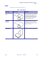
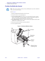
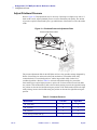
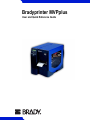
Bradyprinter THT MVPplus Quick Reference Guide
Ribbon
Ribbon
Ribbon is a thin film that is coated on one side with wax, wax resin, or resin, and which is
transferred to the media during the thermal transfer process.
When To Use Ribbon
Thermal transfer media requires ribbon for printing while direct thermal media does not.
To determine if ribbon must be used with a particular media, perform a media scratch test.
To perform a media scratch test, complete these steps:
1. Scratch the print surface of the media with your fingernail.
2. Did a black mark appear on the media?
If a black mark...
Then the media is...
Does not appear on the media
Thermal transfer. A ribbon is required.
Appears on the media
Direct thermal. No ribbon is required.
Coated Side of Ribbon
Ribbon can be wound with the coated side on the inside or outside (Figure 2). This printer can
only use ribbon that is coated on the outside.
Figure 2 • Ribbon Coated on Outside or Inside
Outside
Inside
To determine which side of a ribbon is coated, complete these steps:
1. Peel a label from its liner.
2. Press a corner of the sticky side of the label to the outer surface of the roll of ribbon.
3. Peel the label off of the ribbon.
4. Observe the results. Did flakes or particles of ink from the ribbon adhere to the label?
EN-4
If ink from the ribbon...
Then...
Adhered to the label
The ribbon is coated on the outer surface.
Did not adhere to
the label
The ribbon is coated on the inner surface. To verify this,
repeat the test on the inner surface of the roll of ribbon.
13293LB-12 Rev. 2 16Nov2004
English
Bradyprinter THT MVPplus Quick Reference Guide
Load the Media
Load the Media
This procedure is for loading media in Tear-Off Mode. For loading either fanfold media or roll
media with a printer option, refer to the User Guide.
1. See Figure 3. Press the printhead open lever.
The printhead assembly springs up. Continue to pivot the printhead until it locks into
place.
2. Slide out the media guide as far from the printer frame as possible.
3. Place the roll of media on the media supply spindle.
4. Load the media as shown.
For fanfold or roll media, refer to the User Guide.
5. Slide in the media guide so that it just touches, but does not restrict, the edge of the roll.
6. Close the printhead assembly.
Figure 3 • Load the Media
Media Supply
Spindle
Printhead
Assembly
Printhead
Open Lever
English
Media Guide
13293LB-12 Rev. 2 16Nov2004
EN-5
Bradyprinter THT MVPplus Quick Reference Guide
Position the Transmissive Sensor
This printer uses two types of media sensors: transmissive and reflective. By default, the
printer uses the transmissive sensor, which you can adjust for optimal print performance. The
reflective sensor is a secondary media sensing system that is activated only if the transmissive
sensor cannot be used to calibrate the media.
The transmissive sensor is equipped with a slide-on sensor sleeve (Figure 4). This sleeve has a
notch on one end and a hole in the middle, which help the printer calibrate media that has an
edge notch or an intra-label gap.
Figure 4 • Transmissive Sensor and Sensor Sleeve
Transmissive Sensor
Sensor Sleeve
The lower section of the transmissive sensor has two white vertical positioning marks and a
movable adjustment tab pointer (Figure 5). The positioning marks correspond to the notch and
hole in the sensor sleeve.
Figure 5 • Transmissive Sensor with Adjustment Tab Pointer
Sensor Sleeve
Sensor Sleeve
Positioning
Marks
Adjustment Tab Pointer
(Inner Position)
EN-6
13293LB-12 Rev. 2 16Nov2004
Positioning
Marks
Adjustment Tab Pointer
(Outer Position)
English
Bradyprinter THT MVPplus Quick Reference Guide
Position the Transmissive Sensor
To adjust the transmissive sensor:
1. Press the printhead open lever.
The printhead assembly springs up. Continue to pivot the printhead until it locks into
place.
2. See Figure 4. Locate the transmissive sensor.
3. Push the sensor sleeve all the way in on the transmissive sensor.
4. See Figure 5. Locate the white adjustment tab pointer on the back of the transmissive
sensor.
5. What type of media are you using?
If you are using…
Then…
Non-continuous media
with notched edges
Move the adjustment tab pointer to the inner positioning
mark. The point of the tab should align with the mark.
Non-continuous media
without notched edges
Move the adjustment tab to the outer positioning mark. The
point of the tab should align with the mark.
Continuous media
Move the adjustment tab to the outer positioning mark. The
point of the tab should align with the mark.
Note • Certain types of media may require you to position the adjustment tab to locations
outside of the sensor sleeve.
6. Ensure the media and ribbon are properly positioned.
7. Close the printhead assembly.
English
13293LB-12 Rev. 2 16Nov2004
EN-7
Bradyprinter THT MVPplus Quick Reference Guide
Position the Reflective Sensor
Note • This sensor is typically covered by a factory-installed plate. If you need to enable this
sensor, you must remove the plate.
Refer to Figure 6.
1. Open the printhead assembly and turn on the AC power.
2. Locate the reflective sensor positioning lever.
3. For non-continuous media: Move the lever across the width of the media to align the
reflective sensor with the start-of-label indicator (notch, hole, black mark, or gap). The
glow of the red LED through the media helps to position the sensor.
4. For continuous media: Position the reflective sensor anywhere under the media so that a
“MEDIA OUT” condition can be sensed.
5. Ensure that the media and ribbon are properly positioned.
6. Close the printhead assembly.
Figure 6 • Position the Reflective Sensor
Printhead
Transmissive
Sensor
Reflective
Sensor
Reflective Sensor
Positioning Lever
EN-8
13293LB-12 Rev. 2 16Nov2004
English
Bradyprinter THT MVPplus Quick Reference Guide
Load the Ribbon
Load the Ribbon
Figure 7 • Load the Ribbon
Ribbon take-up spindle
Ribbon
guide plate
Ribbon
supply spindle
Printhead open lever
Important • To protect the printhead from wear, always use ribbon that is wider than the
media.
Note • For direct thermal printing, do not load ribbon in the printer.
Refer to Figure 7.
1. Press the printhead open lever. The printhead assembly springs up. Continue to pivot the
printhead until it “locks” into place.
2. Align the segments of the ribbon supply spindle.
3. Place the ribbon roll on the ribbon supply spindle.
4. Thread the ribbon approximately 18 inches (45 cm) past the printhead assembly.
5. Close the printhead assembly, keeping the ribbon aligned with the guide mark near the left
edge of the ribbon guide plate.
6. Wind the ribbon clockwise onto the ribbon take-up spindle for several turns.
Remove the Ribbon
While holding the ribbon take-up spindle, turn the release knob counterclockwise on the end
of the ribbon take-up spindle. Then, slide the ribbon off the spindle.
English
13293LB-12 Rev. 2 16Nov2004
EN-9
Bradyprinter THT MVPplus Quick Reference Guide
Front Panel
Front Panel
Refer to Figure 8.
Figure 8 • Front Panel
PAUSE
Table 2 • Front Panel Buttons
Front Panel Buttons
Description
FEED
• Press once to feed one blank label.
PAUSE
• Press once to stop the printing process.
• Press again to restart the printing process.
CANCEL
When in Pause Mode, this cancels print jobs.
• Print job(s) in queue: press once for each print job to be deleted.
• Press and hold for more than three seconds to discard all of the label
formats received and return to idle.
• If no label formats are stored, CANCEL will be ignored.
SETUP/EXIT
• Press to enter Configuration Mode.
• Upon completion of the configuration sequence, press to save changes
and exit Configuration Mode.
SELECT
SELECT changes the function of INCREMENT (+) and DECREMENT (–).
• Press SELECT once to use INCREMENT (+) and DECREMENT (–) to
change the value of the selection.
• Press SELECT again to use INCREMENT (+) and DECREMENT (–) to
scroll through the menu items.
EN-10
13293LB-12 Rev. 2 16Nov2004
English
Bradyprinter THT MVPplus Quick Reference Guide
Front Panel
Table 2 • Front Panel Buttons (Continued)
Front Panel Buttons
Description
PLUS (+)
Press (+) to:
• scroll to the next selection
• increase the value
• answer “yes”
• print a label (when applicable)
MINUS (–)
Press (–) to:
• return to the previous selection
• decrease the value
• select the digit you wish to change
• answer “no”
Table 3 • Front Panel LEDs
Front Panel LEDs
Description
POWER
POWER is on when the printer is turned on.
PAUSE
When on, the printer has stopped all printing operations. If the printer is
printing when a pause is requested, the LED turns on at the end of the current
label.
In Peel-Off Mode, the PAUSE LED blinks when the label is available for
removal.
Note • No printing occurs when the printer is in Peel-Off Mode and the
peel-off option is not installed.
ERROR
The ERROR LED is normally off. When an error occurs that causes an
interruption in the printing process, the LED acts as follows:
• SLOW BLINK — “RIBBON IN” warning, “UNDER TEMP” warning, or
“OVER TEMP” error
• FAST BLINK — “PRINTHEAD OPEN” error
• LED ON — “MEDIA OUT,” “RIBBON OUT,” or “CUTTER” errors
The error is displayed on the liquid crystal display (LCD).
DATA
The DATA LED is normally off. When data is received, the LED acts as
follows:
• SLOW BLINK — The printer is unable to accept more data from the host.
• FAST BLINK — The printer is receiving data.
• LED ON — No data is being received. Data processing or printing is still
occurring.
The DATA LED blinks once when CANCEL is pressed and a format is
successfully canceled.
English
13293LB-12 Rev. 2 16Nov2004
EN-11
Bradyprinter THT MVPplus Quick Reference Guide
Configure the Printer
The configuration procedure in the next table contains the information you need to get your
printer up and running, but it is not comprehensive. Refer to the user guide for more
information.
To enter Configuration Mode, press SETUP/EXIT at the PRINTER READY display.
Note • You will need to press (+) more than once to advance to some of the displays.
Remember:
• Press SELECT once to use (+) and (–) to change the value of the selection.
• Press (+) to scroll to the next selection, increase the value, answer “yes,” or print a label
(when applicable).
• Press (–) to return to the previous selection, decrease the value, select the digit you wish to
change, or answer “no.”
• Press SELECT again to use (+) and (–) to scroll to the desired menu item.
Table 4 • Configure the Printer
EN-12
Menu Display
Description
DARKNESS
0 to 30 (default setting is 10)
PRINT MODE
Tear-Off, Peel-Off, Cutter, Rewind (default setting is
Tear-Off)
MEDIA TYPE
Non-continuous, continuous (default setting is noncontinuous)
SENSOR TYPE
Web, mark (default setting is web)
SENSOR SELECT
Auto Select, Reflective, Transmissive (default is
Transmissive)
PRINT METHOD
Thermal transfer, direct thermal (default setting is thermal
transfer)
SAVE CHANGES
Permanent, temporary, cancel, load defaults, load last saved
(default setting is permanent)
PRINTER READY
You have exited Configuration Mode and are ready to print a
test label.
13293LB-12 Rev. 2 16Nov2004
English
Bradyprinter THT MVPplus Quick Reference Guide
Configure the Printer
Print a Test Label
To print a test label:
1. Turn off the printer.
2. Press and hold CANCEL while turning on the printer.
3. Release CANCEL after the first front panel LED turns off.
A configuration label prints showing the printer’s stored parameters (Figure 9).
Figure 9 • Configuration Label
Brady Corporation
Bradyprinter MVP-Series
English
13293LB-12 Rev. 2 16Nov2004
EN-13
Bradyprinter THT MVPplus Quick Reference Guide
Configure the Printer
Adjust Printhead Pressure
Refer to Figure 10. This adjustment may be necessary if printing is too light on one side or if
thick media is used. Adjust printhead pressure to ensure maximum print quality. The amount
of pressure required is determined by the type and thickness of the media as well as the media
width.
Figure 10 • Printhead Pressure Adjustment Dials
Pressure adjustment dials
The pressure adjustment dials for the MVPplus each have four possible settings designated by
blocks of increasing size embossed on the print mechanism. The smallest block (fully
counterclockwise) is considered position 1 and the largest block (fully clockwise) is
considered position 4. Refer to Table 5 to select the initial dial settings for your media.
Some media types require higher pressure to print well. For these media, increase both dials
one position. If the media tends to shift to the left while printing, increase the right dial setting
one position or decrease the left dial setting one position. If the media tends to shift to the right
while printing, increase the left dial setting one position or decrease the right dial setting one
position.
Table 5 • Printhead Pressure
Media Width
EN-14
Left Dial
Right Dial
1 in. (25.4 mm)
3
1
2 in. (51 mm)
4
1
3 in. (76 mm)
3
2
3.5 in. and up (89 mm and up)
3
3
13293LB-12 Rev. 2 16Nov2004
English
Bradyprinter THT MVPplus Quick Reference Guide
Maintenance
Maintenance
Clean the Printer
Note • Use only the cleaning agents indicated. Brady Corporation will not be responsible for
damage caused by any other cleaning materials used on the printer.
The following table provides a recommended cleaning schedule. Use a solvent of 90%
isopropyl alcohol.
Table 6 • Maintenance
Printer Equipment
Cleaning Method
Frequency
Printhead
Solvent*
Platen roller
Solvent*
Media sensors
Air blow
Media path
Solvent*
Ribbon Sensor
Air blow
In Direct Thermal Mode,
after every roll of media or
every 500 feet or 150 m of
fanfold media
In Thermal Transfer Mode,
after every roll of ribbon
(1500 feet or 450 m)
Ribbon path
Solvent*
Cutter
assembly
If cutting
continuous,
pressuresensitive media
Citrus-based
adhesive remover
After every roll of media (or
more often, depending on
your application and media)
If cutting tag
stock or label
liner
Solvent and air blow
After every two or three rolls
of media
Tear-off/peel-off bar
Solvent*
Once a month
Peel blade
Solvent*
After every roll of media (or
more often, depending on
your application and media)
Label-available sensor
Air blow
Once every six months
* Brady recommends using a solvent of 90% isopropyl alcohol or Preventative Maintenance
Kit PCK-4.
English
13293LB-12 Rev. 2 16Nov2004
EN-15
Bradyprinter THT MVPplus Quick Reference Guide
Maintenance
Figure 11 • Clean the Printer
Printhead
Transmissive
Sensor
Take Label
Sensor
Reflective
Sensor
Ribbon
Sensor
Platen
Roller
Clean the Exterior
Clean the exterior of the printer with a lint-free cloth. Do not use harsh, abrasive cleaning
agents or solvents. If necessary, use a small amount of mild detergent or desktop cleaner.
Clean the Interior
Remove any accumulated dirt and lint from the interior of the printer using a soft bristle brush
or vacuum cleaner. Inspect this area after every four rolls of media.
Caution • No lubricating agents of any kind should be used on this printer! Some
lubricants will damage the finish and the mechanical parts inside the printer.
Replace the Fuse
A user-replaceable AC power fuse is located just below the AC power switch at the rear of the
printer. The replacement fuse is a 3AG fast-blow style rated at 5 Amp/250 VAC. Before
replacing the fuse, turn the AC power switch off and unplug the AC power cable.
To replace the fuse, insert the tip of a flat-blade screwdriver into the slot in the end of the fuse
holder end cap. Slightly press in the end cap and turn the screwdriver counterclockwise. The
end cap disengages from the fuse holder and permits removal of the fuse.
To install a new fuse, reverse the sequence.
EN-16
13293LB-12 Rev. 2 16Nov2004
English
Brady Worldwide Identification Solutions
6555 West Good Hope Road
P.O. Box 2131
Milwaukee, WI 53201-2131
Telephone: +1 800.537.8791
Facsimile: +1 800.292.2289
website: ww.bradyid.com
W.H.Brady n.v.
Industriepark C3
Lindestraat 20
B-9240 Zele
Belgium
Telephone: 32 (0) 52 457 811
Facsimile: 32 (0) 52 457 812
website: www.bradyeurope.com
Brady Corporation Asia Pte Ltd
55 Ayer Rajah Crescent #03-25
Ayer Rajah Industrial Estate
Singapore 139949
Telephone: 65-6477-7261
Facsimile: 65-6775-7929
website: www.bradyid.com.sg
Customer Order # 13293L-12
Manufacturer Part # 13293L-12 R2
© 2004 Brady Corp.