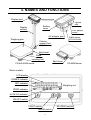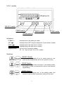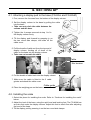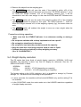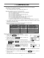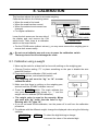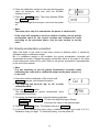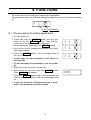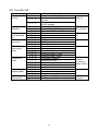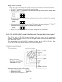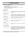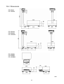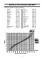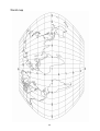
1
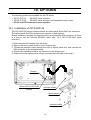
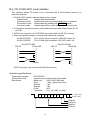
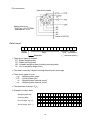
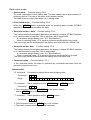
FG Series
Digital Platform Scales
FG-60KAL / FG-150KAL
FG-30KAM / FG-60KAM / FG-150KAM
FG-30KBM / FG-60KBM / FG-150KBM
WM+PD4000966
This manual and Marks
All safety messages are identified by the following, “WARNING” or “CAUTION”, of
ANSI Z535.4 (American National Standard Institute: Product Safety Signs and
Labels). The meanings are as follows:
WARNING
CAUTION
A potentially hazardous situation which, if not avoided,
could result in death or serious injury.
A potentially hazardous situation which, if not avoided,
may result in minor or moderate injury.
This is a hazard alert mark.
This mark informs you about the operation of the product.
This manual is subject to change without notice at any time to improve the
product.
Product specifications are subject to change without any obligation on the part
of the manufacturer.
2004
All rights reserved.
Contents
1. INTRODUCTION .............................................................................................. 2
2. UNPACKING .................................................................................................... 2
3. NAMES AND FUNCTIONS .............................................................................. 3
4. SETTING UP .................................................................................................... 6
4-1. Attaching a display pod to the base (FG-KAL and FG-KAM) ..................... 6
4-2. Installing the scale ..................................................................................... 6
4-3. Power source............................................................................................. 7
5. BASIC OPERATION......................................................................................... 8
5-1. Turning the power ON and OFF ................................................................ 8
5-2. Selecting a weighing unit ........................................................................... 8
5-3. Basic operation.......................................................................................... 8
5-4. Weight display resolution........................................................................... 9
6. COUNTING MODE ......................................................................................... 10
7. COMPARATOR .............................................................................................. 11
8. CALIBRATION ............................................................................................... 12
8-1. Calibration using a weight........................................................................ 12
8-2. Gravity acceleration correction ................................................................ 13
9. FUNCTIONS ................................................................................................... 14
9-1. The procedure for setting parameters...................................................... 14
9-2. Function list ............................................................................................. 15
10. OPTIONS...................................................................................................... 16
10-1. Installation of OP-23/OP-24................................................................... 16
10-2. OP-23 RS-232C serial interface ............................................................ 17
10-3. OP-24 RS-232C serial interface and Comparator relay output.............. 20
11. MAINTENANCE............................................................................................ 21
11-1. Notes on maintenance ........................................................................... 21
11-2 Error codes ............................................................................................. 21
12. SPECIFICATIONS ........................................................................................ 22
12-1. Specifications......................................................................................... 22
12-2. Dimensions............................................................................................ 23
GRAVITY ACCELERATION MAP ...................................................................... 24
1
1. INTRODUCTION
This manual describes how this scale works and how to get the most out of it
in terms of performance.
FG series platform scales have the following features:
? The FG series has three kinds of weight display resolution, 1/3,000, 1/6,000
(1/7,500) and 1/12,000 (1/15,000).
? There are 2 sizes of weighing pan. The FG-KAL has a larger pan and the FGKAM/KBM has a smaller pan. The FG-KAL/KAM has a display column and the FGKBM is a without column model. You can select a model that suits your own
application.
? As power source, you can use an AC adapter or C size dry batteries.
? The counting function easily counts the number of articles of the same weight.
? The comparator function compares the display value with upper limit and lower limit.
The display shows the result and the optional FG-24 can output it as a relay signal.
? The optional FG-23 and FG-24 has an RS-232C interface and can output the
weighing data to connect with a printer, computer and so on.
2. UNPACKING
When unpacking, check whether all of the following items are included:
FG30KAM/60KAM/150KAM
FG60KAL/150KAL
Column support foot
(FG-KAM only)
Protective cover is attached.
(All models)
Scale (Shape is different by model.)
FG series
INSTRUCTION MANUAL
2
3. NAMES AND FUNCTIONS
Display pod
Option
slot
(Bottom)
Battery
cover
Display
column
CAL switch
cover
AC adapter jack
Cable cover
(FG-KAL/KAM)
Weighing pan
Column
support foot
(FG-KAM only)
Spirit level
Base
Leveling foot
Spirit level
FG-KAL/KAM series
FG-KBM series
Metric models
LCD display
STABLE indicator
NET indicator
Weighing unit
ZERO indicator
HI OK LO indicator
ON/OFF switch
PRINT switch
RE-ZERO switch
MODE switch
3
U.S.A. models
Weighing unit
ON/OFF switch
PRINT switch
ZERO switch
TARE switch
MODE switch
Indicators
STABLE ?
Indicates when the reading is stable.
NET ?
Indicates when NET weight is displayed. (Tare function is used.)
ZERO ?
Indicates when the scale zero is correct.
HI
OK
LO
Weighing units
Indicates when the scale zero is correct.
“kg” and “pcs” for metric models
“lb”, “oz”, “kg” and “pcs” for U.S.A. models
Switches
ON/OFF Switch
Used to turn the power on or off. When turned on, the
scale will be automatically set to zero (power-on zero).
PRINT Switch
Outputs the weight value to printer. In the setting mode,
this switch is used to increment the value of the selected
digit blinking.
MODE Switch
Switches the weighing unit. In the setting mode, this
switch is used to store a parameter and go to the next.
4
RE-ZERO Switch
Clears the display to zero. In the setting mode, this
switch is used to select a digit blinking to change its
value.
ZERO Switch
U.S.A. model
Zeroes the scale and turns the display zero. In the
setting mode, this switch is used to select a digit blinking
to change its value.
TARE Switch
U.S.A. model
Subtracts tare (container) weight on the weighing pan.
? The RE-ZERO ,
stable.
ZERO
and
TARE
switches work when the weight value is
? The RE-ZERO and ZERO switches will zero the scale if the weight is within
±2% of the weighing capacity (kg) around the power-on zero point. The ZERO
indicator ? turns on.
? If the weight exceeds +2% of the weighing capacity (kg), the RE-ZERO
will tare the scale. In this case the ZERO and NET indicators turn on.
switch
? The TARE switch will tare the scale when the weight is plus value. In this case
the ZERO and NET indicators turn on.
? The ZERO operation clears tare operation previously done and NET indicator turns
off.
5
4. SETTING UP
4-1. Attaching a display pod to the base (FG-KAL and FG-KAM)
1. First, remove the 4 screws from the bottom of the display column.
Screws
2. Set the display column to the base by pulling the cable
into the base.
? Take care not pinch the cable between the
column and the base.
3. Tighten the 4 screws removed at step 1 to fix
the display column firmly.
4. Tilt the display pod forward by pressing in on
the two round side clamps, and slide off the
cable cover.
5. Pull the bundle of cable out from the top end of
display column, feeding all of slack of the
cable on the base into the display column.
? Take care not scratch the cable.
Cable cover
Cable
Neither slack
Nor tension
6. Put the bundle of cable back into the display column.
7. Make sure the cable is fitted to the 2 cable
guides and attach the cable cover.
Cable guide
8. Place the weighing pan on the base.
4-2. Installing the scale
1. Select the place for installing the scale. Refer to “Cautions for installing the scale”
below.
2. Adjust the level of the base, using the spirit level and leveling feet. The FG-KAM has
an extra foot under the display column. Adjust this foot to reach floor after adjusting
the level of the base.
3. Tilt the display pod by pressing in on the two round side clamps.
6
Cautions for installing the scale
Consider the following conditions to get the most out of your scale.
? Install the scale where the temperature and relative humidity is stable. There is no
draft and a stable power source is available.
? Install the scale on a solid and level surface.
? Do not install the scale in direct sunlight.
? Do not install the scale near heaters or air conditioners.
? Do not install the scale where there is flammable or corrosive gas present.
? Do not install the scale near equipment which produces magnetic fields.
? Do not install the scale where there is apt to be static electricity, in a place where
the relative humidity is lower than 45% RH. Plastic and isolators are apt to be
charged with static electricity.
? Do not use an unstable power source.
? When the scale is installed for the first time, or the scale has been moved, carry out
calibration as described in “8. CALIBRATION”.
4-3. Power source
For the power source, the AC adapter or C size dry cells can be used.
When using the AC adapter
Use a stable power source. To use the AC adapter, insert the AC adapter plug into the
AC adapter jack on the rear side of display pod.
? Confirm the AC adapter type is correct for your local voltage.
When using the batteries
Prepare 4 x C size (R14P/LR14) dry batteries. The batteries are not included in the
product. The scale can be used continuously for about 150 hours using the alkaline
batteries.
1. Turn of the scale and disconnect the AC adapter if used.
2. Slide the battery cover off
3. Push the battery case inside the display pod and take it out.
4. Insert four new dry cells into the battery case.
5. Push the battery case into the display pod as before.
6. Attach the battery cover.
? Take great care of the polarity of batteries. The polarity marks are
shown in the battery case.
? Replace used batteries with four new ones when “lb0” is displayed.
? Do not mix used and new batteries. It may cause damage to the
battery or product, if used.
? Do not mix the battery type. It may cause damage to the battery or
product.
? The battery life depends on the ambient temperature.
? Remove batteries from display pod when the scale is not to be used
for a long time. They may leak and cause damage.
? Damage due to battery leakage is not covered by the warranty.
7
5. BASIC OPERATION
5-1. Turning the power ON and OFF
1. Press the ON/OFF switch to turn the power ON.
All the display symbols are displayed and the scale waits for the weighing data to
become stable.
(Only the units available illuminate.)
After the weighing value internally becomes stable, the display turns off for a
moment and zero is shown with the ZERO indicator (power-on zero).
If the weighing value is unstable, the display shows “------”. Check if anything
touches the weighing pan, or check if there is strong wind or vibration.
The range for power-on zero is within ±10% of the weighing capacity (kg) around
the calibrated zero point.
If the power is switched ON while there is a load beyond this range, the scale shows
“------”. Remove the load on the weighing pan.
2. Pressing the
ON/OFF
switch again, and the power will be switched OFF.
? Auto power-off function
It is possible to have the power automatically switched OFF, if zero is displayed for
approximately 5 minutes. See “9-2. Function list” and set the function “F1-1” or “F12” .
5-2. Selecting a weighing unit
Press the
MODE
switch to select a weighing unit.
lb
oz
kg
pcs
? “lb” and “oz” will be available for U.S.A. models only.
? For U.S.A. models, it is possible to specify the display unit “lb”, ”oz” or ”kg” that will
shown first when the power is switched on. See “Function list F3”.
5-3. Basic operation
1. Turn the display on via the
ON/OFF
2. Select a weighing unit using the
switch.
MODE
switch.
3. When the display doesn’t show zero, press the
set the display to zero.
RE-ZERO
(
ZERO
) switch to
4. When using a tare (container), place the container on the weighing pan, and press
the RE-ZERO ( TARE ) switch to set the display to zero.
5. Place the object to be weighed on the pan or in the container, and wait for the
STABLE indicator to be displayed and read the value.
8
6. Remove the object from the weighing pan.
? The RE-ZERO switch will zero the scale if the weight is within ±2% of the
weighing capacity (kg) around the power-on zero point. The ZERO indicator ? turns
on. When the weight exceeds +2% of the weighing capacity (kg), it will be
subtracted to zero as a tare weight. In this case the ZERO and NET indicators turn
on.
? The ZERO switch will zero the scale if the weight is within ±2% of the weighing
capacity (kg) around the power-on zero point. The ZERO indicator ? turns on.
When the weight exceeds ±2% of the weighing capacity (kg), the switch does not
work.
? The TARE switch will subtract the weight to zero as a tare weight when the
weight is a plus value.
Precautions during operation
? Make sure that the STABLE indicator is on whenever reading or storing a
value.
? Do not press switches with a sharp implement such as a pencil.
? Do not apply a shock load to the scale.
? Do not place a load onto the pan that exceeds the capacity.
? Keep the scale free from foreign objects such as dust or liquid.
? Calibrate the scale periodically to keep weighing accuracy.
(See “8. CALIBRATION”.)
5-4. Weight display resolution
The FG series has three kinds of weight display resolution, NORMAL, HIGH and
HIGHER. The following is about “kg” and “lb” display for reference. See the “12.
SPECIFICATIONS” in detail.
NORMAL:
HIGH:
HIGHER:
1/3,000
1/6,000 ~ 1/7,500 (depending on capacity)
1/12,000 ~ 1/15,000 (depending on capacity)
The factory setting is the HIGH resolution, but it is possible to change by Function
settings “F2”. Set this function according to the application.
? In some countries, the resolution will be limited NORMAL only, and the setting F2 is
not available.
? In the COUNTING mode, the scale works as in the HIGHER resolution regardless
of weight display resolution.
9
6. COUNTING MODE
Determines a unit weight (the weight of one piece) from sample pieces, and calculates
how many pieces on the weighing pan using the unit weight.
1. Press the
MODE
switch to select “pcs”.
(“pcs” = pieces)
2. Press and hold the MODE switch to enter
the sample unit weight storing mode.
3. To select the number of samples, press the
PRINT switch. It may be set to 5, l0, 20, 50
or l00.
ZERO ?
0
ZERO ?
5 0
ZERO ?
20 -
Confirm the display
4. If necessary, place a container on the weighing
pan, and press the RE-ZERO ( TARE )
switch. Confirm that the right side of the number
of samples shows zero.
ZERO ?
20 0
5. Place the correct number of samples on the pan
or in the container.
20 -
6. Press the MODE switch to calculate and
store the unit weight. Remove the sample. The
scale is set to count objects with this unit weight.
20
? The total weight of sample pieces should be more than below regardless
of number of sample pieces.
FG-30K: 25 g
FG-60K: 62.5 g
FG-150K: 125 g
If not, the display shows “lo ut” and returns to the previous display.
Increase the number of samples (go to step 3) and try again.
? If pressing the MODE switch without adding sample pieces or adding
enough weight to be acceptable as a unit weight, the display leaves
counting mode and switches to the next weight unit.
7. Place the objects to be counted on the pan.
? Unit weigh is maintained even if the scale is powered off.
10
234
7. COMPARATOR
The results of the comparison are indicated by HI, OK or LO on the display.
The formula to compare is as follows:
LO < Lower limit value = OK = Upper limit value < HI
Operating conditions (see the “Function list F6”):
F6-0: No comparison (comparator function disabled).
F6-1: To compare all data.
F6-2: To compare more than +4d or less than -4d.
F6-3: To compare all stable data.
F6-4: To compare stable data more than +4d or less than -4d.
F6-5: To compare stable data more than +4d.
d = minimum weight display (see “12-1 Specifications”)
In case of counting mode, “d” is equal to minimum weight display of kg mode.
? The upper limit and lower limit numerical values are common to each of the
weighing and counting mode.
? Ignore the decimal point of setting value to apply it to each mode.
Example of FG30K / setting value is “001000”.
Display mode
NORMAL resolution kg
HIGH resolution kg
HIGHER resolution kg
NORMAL resolution lb
HIGH resolution lb
HIGHER resolution lb
Counting mode
Limit value
10.00 kg
1.000 kg
1.000 kg
10.00 lb
10.00 lb
1.000 lb
1000 pcs
Display capacity
30.00 kg x 0.01 kg
30.000 kg x 0.005 kg
30.000 kg x 0.002 kg
60.00 kg x 0.02 lb
60.00 kg x 0.01 lb
60.000 kg x 0.005 lb
Entering the upper and lower limit values
1. Press the
MODE
unit ”kg”, ”lb” or ”oz”
switch to select weighing
2. Press and hold the MODE
upper limit setting mode.
0.00
switch to enter the
0000.00
3. Enter an upper limit value using the following switches.
RE-ZERO
PRINT
or
ZERO
HI
To select the digit blinking to change.
Increment the value of the selected digit.
The minus sign can be set at the next digit of the least
significant digit. The PRINT switch alternates the
minus sign on and off. The blinking “-” shows minus
and no sign is plus.
-0000.00
HI
4. After setting all of digits, press the MODE switch. Then, the upper limit is stored
and the display goes to the lower setting mode.
5. Set the lower limit in a similar way, and press the
weighing mode.
MODE
switch to return to
? The upper and lower limits are maintained even if the scale is powered off.
11
8. CALIBRATION
This function adjusts the scale for accurate weighing.
Calibrate the scale in the following cases.
? When the scale is first used.
? When the scale has bee moved.
? When the ambient environment has
changed.
? For regular calibration.
Connector
Lock screw
Loose the lock screws on the rear side of
the display pod, and remove the CAL
switch cover. Then, there is a calibration
switch on the board inside.
Calibration (CAL) switch
CAL switch cover
? For the FG-KB series (without column), you may once remove the weighing pan to
access lock screws easily.
? Do not use a ballpoint pen and so on to press the calibration switch.
That may short-circuit and damage the scale.
8-1. Calibration using a weight
1. Warm up the scale for at least half an hour with nothing on the weighing pan.
? Change Function setting “F1” or place something on the pan to disable the auto
power-off function.
2. Press and hold the calibration (CAL) switch until
Cal 0 appears, and release the switch.
? The weighing unit must be “kg” or “lb” to enter
calibration mode.
Cal 0
3. Make sure that there is nothing on the weighing pan,
and wait until the STABLE indicator turns on.
5pn 1
4. Press the MODE switch. The scale calibrate the
zero point, and the display shows “5pn 1” and the
weight value to calibrate (SPAN calibration).
60.00
? The weight value is equal to the capacity. When
you enter with “kg” mode, then the value is “kg”.
Entering with “lb”, then “lb”.
? If you do not need SPAN calibration, turn the power off to exit from the calibration
procedure.
5. To calibrate with the different weight, change the displayed value using the following
switches.
RE-ZERO
PRINT
or
ZERO
To select the digit blinking to change.
Increment the value of the selected digit.
12
6. Place the calibration weight on the pan with the same
value as displayed, and wait until the STABLE
indicator turns on.
40.00
7. Press the MODE switch. The scale calibrate SPAN
and end
will appear.
end888
Remove the weight from the pan, and turns the power
off.
? Note
The value set in step 5 is cleared after the power is switched off.
If the scale will suppose to move to another location, set the gravity
acceleration value for the current location and calibrate the scale
according to the procedure above. See the next section to set the
value.
8-2. Gravity acceleration correction
When the scale is first used or has been moved to different place, it should be
calibrated using a calibration weight.
But if a calibration weight is not available, the gravity acceleration correction will
compensate the scale. Change the gravity acceleration value of the scale to the value
of area where the scale will be used. Refer to the gravity acceleration map appended
to the end of this manual.
? Note
It is not necessary to set the gravity acceleration correction when
calibrating the scale with a calibration weight at the place where it is
to be used.
1. Press and hold the calibration (CAL) switch until
Cal 0 appears, and release the switch.
? The weighing unit must be “kg” or “lb” to enter
calibration mode.
2. Press the PRINT switch.
The display shows the gravity acceleration value
memorized in the scale.
Cal 0
9.798
3. To change the displayed value using the following switches.
RE-ZERO
or
PRINT
4. Press the
MODE
ZERO
To select the digit blinking to change.
Increment the value of the selected digit.
switch. The display returns to
Cal 0 .
5. If necessary to calibrate the scale using a calibration weight, go to step 3 of “8-1.
Calibration using a weight”. To finish the setting, turn the power off.
13
9. FUNCTIONS
The scale has Function settings to expand your applications.
The parameters set in the Function settings are maintained even if the power switched
off.
f 1- 1
Item
Parameter
9-1. The procedure for setting parameters
1. Turn the power off.
2. Press and hold the ZERO switch and turn the
power on via the ON/OFF switch. Then, the first
function item and its parameter is displayed.
3. Set the parameter value using the PRINT switch.
? If you do not need to change the parameter, go to next
step without setting.
4. Press the MODE switch. Then the display goes to
the next function item.
? In this stage, the new parameter is not stored in
the scale yet.
f 1- 1
f 1- 0
f 2- 1
? To end changing the parameters, turn the power
off.
5. Repeat the steps 3 and 4 to the last item.
6. After setting the last item, press the
Then, end
will appear.
MODE
switch,
7. Press the MODE switch again. The parameters are
stored in the scale, and the scale will automatically boot
up.
? If you turn the power off before this step is done,
none of the parameters will be changed.
14
end888
9-2. Function list
Item
Auto power-off
function
f 1- 0
? f 1- 1
f 1- 2
Display
resolution
Weighing unit
when powered
on
RS-232C
Baud rate
RS-232C
Data output
mode
Comparator
mode
Filtering to
weighing data
RS-232C
Data format
Description
Auto power-off disabled
Auto power-off enabled for battery
use only
Auto power-off enabled for battery
and AC adapter
Normal (1/3,000 class)
High (1/6,000~1/7,500 class)
Higher (1/12,000~1/15,000 class)
lb
oz
kg
2400 bps
4800 bps
9600 bps
Stream mode
Command mode
f 2- 0
? f 2- 1
f 2- 2
? f 3- 0
f 3- 1
f 3- 2
? f 4- 0
f 4- 1
f 4- 2
? f 5- 0
f 5- 1
Print switch mode
f 5- 2
Auto-print mode +/- data
f 5- 3
Auto-print mode + data
f 5- 4
? f 6- 0
Comparator disabled
Compares all data
f 6- 1
Compares data > +4d or < -4d
f 6- 2
Compares all stable data
f 6- 3
Compares stable data > +4d or < -4d
f 6- 4
Weak / fast response
f 7- 0
? f 7- 1
Normal / normal response
Strong / slow response
f 7- 2
? f 8- 0
Reply is sent
No reply except “Q” command
f 8- 1
?Factory setting
15
Automatically
power off
Legal for trade
will be Normal.
U.S.A. models
only
Conditions to
compare.
d = minimum
display division
Reaction to the
command
10. OPTIONS
The following options are available for the FG series:
? OP-23 (FG-23)
RS-232C serial interface
? OP-24 (FG-24)
RS-232C serial interface and Comparator relay output
? OP-23 and OP-24 cannot be used together.
10-1. Installation of OP-23/OP-24
The OP-23/OP-24 has an interface board, an option panel and a DIN 8 pin connector.
The option panel and DIN connector are common to both options.
Before installation, prepare an interface cable using attached DIN connector. Or there
is a way to use the optional RS-232C cable (see “10-2. OP-23 RS-232C serial
interface”).
1. Disconnect the AC adapter from the scale.
2. Remove the four screws and the cover of option slot.
3. Thread the interface cable through the hole of option panel first, and connect the
DIN connector to the interface board.
4. Connect the interface board to the connector in the display pod.
5. Attach and fix the option panel using the screws that removed in the step 2.
Screws
`
Option slot for OP-23/24
(Cover)
Interface board
Option panel
Interface cable
16
10-2. OP-23 RS-232C serial interface
This interface allows FG series to be connected with a multi-function printer or a
personal computer.
? The RS-232C interface has the following four modes.
Stream mode
Outputs data continuously.
Command mode
Controls the scale using commands from a computer.
Print switch mode
Outputs data by pressing the PRINT switch..
Auto-print mode
Outputs data which meets the conditions of auto-print.
? If necessary, set the parameter of the data format and data output mode (F4, F5
and F8).
? A DIN 8 pin connector (JA+TCP0586) is provided with the OP-23 for wiring.
? There are optional cables to connect with a personal computer.
AX-KO577A-200
AX-KO1786-200
FG to D-Sub 25 pin computer / RS-232C cable, 2m
FG to D-Sub 9 pin computer / RS-232C cable, 2m
AX-KO577A-200
DIN 7P
D-Sub 25P
1
1
2
2
3
3
4
4
5
5
6
6
7
7
others
AX-KO1786-200
DIN 7P
D-Sub 9S
1
1
2
2
3
3
4
4
5
5
6
6
7
7
8
9
(DIN 7 pin plug P can connect with DIN 8 pin socket.)
Interface specifications
Transmission system
Transmission form
Data format
EIA RS-232C
Asynchronous, bi-directional, half-duplex
Baud rate:
2400, 4800, 9600 bps
Data:
7 bits + parity 1bit (even)
Start bit:
1 bit
Stop bit:
1 bit
Code:
ACII
Terminator:
CRLF (CR: 0Dh, LF: 0Ah)
LSB
0
1
2
3
4
5
MSB
6
1 (-15V~-5V)
0 (5V~15V)
Stop bit
Parity bit
Data bit
Start bit
17
Pin connections
View from outside
Mating connector:
DIN 8 pin (JA+TCP058)
Attached to FG-23.
NC
NC
NC
NC
(Inside of OP-23)
Data format
S
T
,
+
0
0
0
Header
0
0
.
0
0
_
k
Data
Unit
g CR LF
Terminator
(“_” shows a space.)
Separator
? There are 4 types of headers:
ST : Stable weighing data
QT : Stable counting data
US : Unstable weighing data (including counting data)
OL : Out of weighing range (Over)
? The data is normally 9 digits including decimal point and a sign.
? There are 4 types of units:
_ k g : Weighing data “gram”
_ P C : Counting data “pcs”
_ l b : Weighing data “decimal pound”
_ o z : Weighing data “decimal ounce”
? The terminator is always CRLF.
? Example of output data:
S T
,
+ 0 0 1
2 3
.
Counting data
Q T
,
+ 0 0 0
1 2
3 4 5 _ P C CR LF
Out of range “kg” (+)
O L
,
+ 9 9 9
9 9
.
Out of range “pcs” (-)
O L
,
-
9 9
9 9 9 _ P C CR LF
18
9 9 9
4 5 _
9 9 _
k
g CR LF
Weighing data “kg”
k
g CR LF
Data output mode
? Stream mode
Function setting “F5-0”
The scale outputs the current display data. The data-update rate is approximately 10
times per second. This rate is the same as the display-update.
The scale does not output data while it is in setting mode.
? Print switch mode
Function setting “F5-2”
When the PRINT switch is pressed while the weighing data is stable (STABLE
indicator is on), the scale transmits the data.
? Auto-print mode +/- data
Function setting “F5-3“
The scale transmits the weighing data when the display is stable (STABLE indicator
is on) and the data is more than +4d or less than -4d of weight data.
d = minimum weight display (see “12-1 Specifications”)
When in counting mode, “d” is equal to minimum weight display of kg mode.
The next output can be obtained after the display returns to between -4d and +4d.
? Auto-print mode + data
Function setting “F5-4“
The scale transmits the weighing data when the display is stable (STABLE indicator
is on) and the data is more than +4d of weight data.
d = minimum weight display (see “12-1 Specifications”)
When in counting mode, “d” is equal to minimum weight display of kg mode.
The next output can be obtained after the display returns to below +4d.
? Command mode
Function setting “F5-1
In the command mode, the scale is controlled by commands that come from the
personal computer and so on.
Command list
“Q” command
Command to request the current weighing data.
Command
Q CR LF
Reply
S T ,
“Z” command
Command
+ 0 0 1 2 3
Same operation as the
.
4 5 _ k g CR LF
RE-ZERO
or
ZERO
Z CR LF
? This command works as RE-ZERO
and as ZERO for U.S.A. models.
for the metric models
“T” command
TARE
Command
Same operation as the
switch.
T CR LF
? This command works as TARE for U.S.A. models.
? The metric models cannot accept this command.
19
switch.
Reply to the command
When the “F8-0” is selected, the scale reacts to the received command as follows.
? For the “Q” command, the scale will send the data.
? For the “Z” and “T” commands, the scale will send the same code as a reply after
executing the command.
Reply
Z CR LF
Reply
T CR LF
When the command cannot execute because the scale is unstable, for example,
“I” will be sent.
Reply
I CR LF
? If the received command is not for the FG series, the scale will send “?”. The “T”
command for the metric model is included to this group.
Reply
? CR LF
? When “F8-1” is selected, there is no reply except the “Q” command.
10-3. OP-24 RS-232C serial interface and Comparator relay output
The OP-24 has an RS-232C series interface and relay output for the comparator
function. It allows output of the HI, OK or LO signal results to an external device as a
solid state relay output.
The specification for the RS-232C interface is same as the OP-23 (FG-23).
“10-2. OP-23 RS-232C serial interface” for further information.
Interface specifications
Pin connections
View from outside
Mating connector:
DIN 8 pin (JA+TCP058)
Attached to FG-24.
(Inside of OP-24)
Maximum rating for relay is as follows.
? Maximum voltage:
50V DC
? Maximum current:
100mA DC
? Maximum ON resistance: 35?
20
See
11. MAINTENANCE
11-1. Notes on maintenance
? Do not disassemble the scale. Contact your local A&D dealer if your scale
needs service or repair.
? Please use the original packaging for transportation.
? Do not use organic solvents to clean the scale. Use a warm lint free cloth
dampened with a mild detergent.
11-2 Error codes
Overload error
888e888
Warning to indicate that an object beyond the scale
capacity has been placed on the pan. Remove the object
from the pan.
Range over notice
88-e888
This will be shown if the weight sensor receives strong
force upward. Check if the weighing pan is touching
anything or if there is anything in the base. There is a
possibility that the weight sensor itself may have a failure.
Unit weight error
88lo8ut
The sample weight is too light to set the unit weight in the
counting mode. Increase the sample numbers.
Low battery
888lb08
Warning to show that the batteries are exhausted.
Replace them with new batteries.
Low power
888lb18
Warning to show that the voltage of main power source is
too low.
Memory writing error
88err13
This may be shown that the scale fails to store
parameters when the calibration, function setting, unit
weight registration, comparator limits setting and so on
have been done. Turn the power off once and try the
above procedure again. If this error happens again, there
is a defect in the memory device.
If you cannot cancel an error or other errors occur, request service from the store
where you purchased the product or to your A&D dealer.
21
12. SPECIFICATIONS
12-1. Specifications
FG-30KAM
FG-30KBM
FG-60KAM
FG-60KBM
FG-150KAM
FG-150KBM
FG-60KAL
FG-150KAL
30
60
150
60
150
0.01
0.005 *
0.002
0.02
0.01 *
0.005
0.05
0.02 *
0.01
0.02
0.01 *
0.005
0.05
0.02 *
0.01
60
150
300
150
300
0.02
0.01 *
0.005
0.05
0.02 *
0.01
0.1
0.05 *
0.02
0.05
0.02 *
0.01
0.1
0.05 *
0.02
Weight capacity
(oz)
960
2400
4800
2400
4800
Min. display
(oz)
0.5
0.2 *
0.1
MODEL
Weight capacity
(kg)
Min. display
(kg)
Weight capacity
(lb)
Min. display
(lb)
No. of samples
Max. counts
Min. unit weight
Repeatability
(Std. deviation)
Linearity error
Sensitivity drift
Display
Display update
Operating temp.
Power supply
Battery operating
Weighing
pan
size
Dimension
Weight
(approximately)
Calibration weight
(Factory setting)
1
2
1
2
0.5 *
1*
0.5 *
1*
0.2
0.5
0.2
0.5
5 (can be changed to 10, 20, 50 or 100) pieces
120,000 pcs
96,000 pcs
120,000 pcs
96,000 pcs
120,000 pcs
0.25 g
0.625 g
1.25 g
0.625 g
1.25 g
0.005 kg
0.01 kg
±0.01 kg
0.02 kg
0.01 kg
0.02 kg
±0.02 kg
±0.05 kg
±0.02 kg
±0.05 kg
±20 ppm / °C (10°C~30°C / 50°F~86°F)
7 segment LCD display (Character height 26 mm)
10 times per second
-10°C~40°C / 14°F~104°F, less than 85% R.H. (non-condensing)
AC adapter or C size (R14P / LR14) x 4 batteries
Approximately 150 hours with alkaline dry cell battery
390 x 530 mm
300 x 380 mm / 11.8 x 15.0 in.
15.4 x 20.9 in.
FG-KAM: 300(W) x 624(D) x 781(H) mm
11.8(W) x 24.6(D) x 30.7(H) in.
390(W) x 771(D) x 781(H) mm
FG-KBM: 380(W) x 464(D) x 118(H) mm
15.4(W) x 30.4(D) x 30.7(H) in.
15.0(W) x 18.3(D) x 4.6(H) in.
FG-KAM: 11.2 kg
16.4 kg
FG-KBM: 9.7 kg
30 kg
60 kg
150 kg
60 kg
150 kg
60 lb
150 lb
300 lb
150 lb
300 lb
*) Factory setting
22
12-2. Dimensions
781
FG-60KAL
FG-150KAL
390
289
128
99
530
300
440
781
FG-30KAM
FG-60KAM
FG-150KAM
82
202
118
300
89
380
300
220
FG-30KBM
FG-60KBM
FG-150KBM
230
89
300
300
118
145
380
220
mm
23
GRAVITY ACCELERATION MAP
Values of gravity at various locations
Amsterdam
Athens
Auckland NZ
Bangkok
Birmingham
Brussels
Buenos Aires
Calcutta
Cape Town
Chicago
Copenhagen
Cyprus
Djakarta
Frankfurt
Glasgow
Havana
Helsinki
Kuwait
Lisbon
London (Greenwich)
Los Angeles
Madrid
9.813 m/s2
9.807 m/s2
9.799 m/s2
9.783 m/s2
9.813 m/s2
9.811 m/s2
9.797 m/s2
9.788 m/s2
9.796 m/s2
9.803 m/s2
9.815 m/s2
9.797 m/s2
9.781 m/s2
9.810 m/s2
9.816 m/s2
9.788 m/s2
9.819 m/s2
9.793 m/s2
9.801 m/s2
9.812 m/s2
9.796 m/s2
9.800 m/s2
Manila
Melbourne
Mexico City
Milan
New York
Oslo
Ottawa
Paris
Rio de Janeiro
Rome
San Francisco
Singapore
Stockholm
Sydney
Taichung
Taiwan
Taipei
Tokyo
Vancouver, BC
Washington DC
Wellington NZ
Zurich
24
9.784 m/s2
9.800 m/s2
9.779 m/s2
9.806 m/s2
9.802 m/s2
9.819 m/s2
9.806 m/s2
9.809 m/s2
9.788 m/s2
9.803 m/s2
9.800 m/s2
9.781 m/s2
9.818 m/s2
9.797 m/s2
9.789 m/s2
9.788 m/s2
9.790 m/s2
9.798 m/s2
9.809 m/s2
9.801 m/s2
9.803 m/s2
9.807 m/s2
World map
25
MEMO
26
MEMO
27
MEMO
28
3-23-14 Higashi-Ikebukuro, Toshima-ku, Tokyo 170-0013 JAPAN
Telephone: [81] (3) 5391-6132 Fax: [81] (3) 5391-6148
A&D ENGINEERING, INC.
1555, McCandless Drive, Milpitas, CA. 95035 U.S.A.
Telephone: [1] (408) 263-5333 Fax: [1] (408) 263-0119
A&D INSTRUMENTS LTD.
Unit 24/26 Blacklands Way, Abingdon Business Park, Abingdon, Oxon OX14 1DY United Kingdom
Telephone: [44] (1235) 550420 Fax: [44] (1235) 550485
<German Sales Office>
Große Straße 13 b 22926 Ahrensburg GERMANY
Telephone: [49] (0) 4102 459230 Fax: [49] (0) 4102 459231
A&D MERCURY PTY. LTD.
32 Dew Street, Thebarton, South Australia 5031 AUSTRALIA
Telephone: [61] (8) 8301-8100 Fax: [61] (8) 8352-7409
A&D KOREA Limited
8th Floor, Manhattan Bldg. 36-2 Yoido-dong, Youngdeungpo-ku, Seoul, KOREA
Telephone: [82] (2) 780-4101 Fax: [82] (2) 782-4280