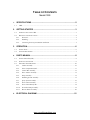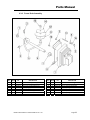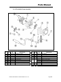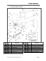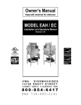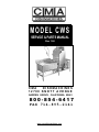
1
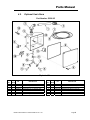
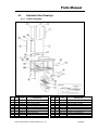
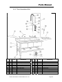
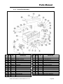
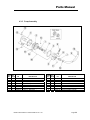
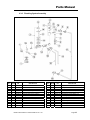
MODEL CWS
SERVICE & PARTS MANUAL
Rev 1.00
CMA
DISHMACHINES
12700 KNOTT AVENUE
GARDEN GROVE, CALIFORNIA 92841
800-854-6417
FAX 714-895-2141
www.cmadishmachines.com
TABLE OF CONTENTS
Model CWS
1.
SPECIFICATIONS .........................................................................................2
1.1
2.
3.
4.
5.
CWS ............................................................................................................................................... 2
GETTING STARTED .....................................................................................3
2.1.
INTRODUCTION TO THE CWS .......................................................................................................... 3
2.2.
RECEIVING AND INSTALLATION ...................................................................................................... 4
2.2.1.
Electrical ................................................................................................................................ 4
2.2.2.
Plumbing................................................................................................................................. 4
2.2.3.
Connecting the Scrap Accumulator and Drain....................................................................... 5
OPERATION..................................................................................................6
3.1.
INITIAL SETUP ................................................................................................................................. 6
3.2.
STARTUP PROCEDURES ................................................................................................................... 7
PARTS MANUAL ..........................................................................................8
4.1.
INITIAL PARTS KIT (P/N)................................................................................................................. 8
4.2.
OPTIONAL SANI ALARM .................................................................................................................. 9
4.3.
EXPLODED VIEW DRAWINGS......................................................................................................... 10
4.3.1.
Cabinet Assembly ................................................................................................................. 10
4.3.2.
Three Compartment Sink ...................................................................................................... 11
4.3.3.
Control Box Assembly .......................................................................................................... 12
4.3.4.
Door Actuator Assembly....................................................................................................... 13
4.3.5.
Pump Assembly..................................................................................................................... 14
4.3.6.
Plumbing System Assembly................................................................................................... 15
4.3.7.
Spray System Assembly......................................................................................................... 16
4.3.8.
Power Drain Assembly ......................................................................................................... 17
4.3.9.
Power Drain Retrofit Kit ...................................................................................................... 18
4.3.10.
Peristaltic Pump Assembly ................................................................................................... 19
4.3.11.
Booster Heater Assembly...................................................................................................... 20
ELECTRICAL DIAGRAM ............................................................................21
www.cmadishmachines.com
1. Specifications
Electrical and plumbing connections must be made by a qualified service person who will
USAElectrical,METRIC
Plumbing and Safety
comply with all available Federal, State, and Local Health,
1.1
CWS
WATER CONSUMPTION
PER RACK
1.7 GAL.
(6.4 L)
PER HOUR
51 GPH.
(193 LPH)
OPERATING CYCLE
WASH TIME-SEC.
57
57
RINSE TIME-SEC.
48
48
DWELL TIME-SEC.
15
15
120 SEC.
120 SEC.
30
30
WASH TANK CAPACITY
1.7 GAL.
(6.4 L)
PUMP CAPACITY
68 GPM
(257 LPM)
REQUIRED MINIMUM TEMP.
120°F
(49°C)
RECOMMENDED TEMP.
140°F
(60°C)
TOTAL CYCLE
OPERATING CAPACITY
RACKS PER HOUR
WATER REQUIREMENTS
WATER INLET
3/4”
—
2”
—
1-1/2”
—
DEPTH
31”
(78.7 cm)
WIDTH CWS
102”
(259 cm)
120-1/4”
(305 cm)
HEIGHT
68”
(172 cm)
MAX CLEARANCE FOR DISHES
27”
(68 cm)
STRANDARD RACKS
19 ¾” x 19 ¾”
(50 x 50 cm)
ELECTRICAL RATING
VOLTS
(60-Hz)
AMPS
SINGLE PHASE
208
57
SINGLE PHASE
240
62
THREE PHASE
208
38
THREE PHASE
240
40
DRAIN -MACHINE
DRAIN-SINKS
DIMENSIONS
WIDTH CWS W/DRAIN BOARD
WASH PUMP MOTOR
2 HP
SHIPPING WEIGHT
APPROXIMATE
MODEL CWS SERVICE & PARTS MANUAL Rev. 1.00
708#
(321 kg)
Page 2
Getting Started
2. Getting Started
2.1.
Introduction to the CWS
The CWS Dishmachine is safe and easy to operate with its “Auto Start/Stop” and it’s economical
to operate—using only 1.7gallons of water per cycle. The CWS Dishmachine’s top mounted
controls include built-in chemical pumps and a de-liming system that assures proper chemical
usage. Its integrated scrap tray prevents food soil from entering the drain system. The CWS can
be run at a rate of 30 racks / 120 covers per hour and its heavy duty stainless steel construction
assures long life and years of trouble free operation.
The supply water to the dishmachine should be 140°F. The pipe supplying the water must be ¾”
minimum. The supply water connects to the gate valve located at the back of the machine (¾”
female pipe thread connection). Temp Sure Hot Water Assurance System guarantees hot water
every cycle. The drain is 2" and comes off of the scrap accumulator for easy attachment of your
drain line. See section 2.2.3 Connecting the Scrap Accumulator and Drain
The CWS conceals a three-compartment sink within the soiled dishtable that complies with local
health code requirements.
This manual is structured to provide a complete reference guide to the CWS Dishmachine. It is
presented in a manner that all users will be able to comprehend and use as an effective tool in
supporting the operation and maintenance of the dishmachine. The first section explains how the
machine is packaged and what to look for when receiving the machine.
After unpacking the machine, this manual explains how to install and set up the machine for use.
Requirements are given for plumbing, wiring, and space considerations. These attributes of the
machine are always taken into consideration by our well-trained sales representatives prior to the
order being placed. In the manual, guidance is also given for installation to ensure that the
machine will be able to run at optimum conditions.
The Operation section of the manual may be used for instruction and procedures when required.
We make this portion of the manual easy to understand so that all levels of operators may be
able to read and comprehend the operation of the machine. The function of the machine itself is
mostly automatic and takes little training to put into full operation.
A wiring diagram for the machine is located at the end of the manual.
CMA warranties the workmanship of the machine.
We are committed to providing the best machines and customer service in the food industry and
your feedback is welcome.
MODEL CWS SERVICE & PARTS MANUAL Rev. 1.00
Page 3
Getting Started
2.2.
Receiving and Installation
The dishwasher is shipped from the factory in a corrugated box on a wooden pallet. The
installation guidelines give a systematic procedure for setting up the machine.
Start by removing the dishmachine from the box. Remove the packaging, unwrap the machine
and check for the following components:
Scrap Accumulator complete with lid and scrap tray.
Inside the wash tank is a box with one control box key, 4 legs, thermometer, spray
arms, machine manual and a cam timer wrench.
Tube Stiffeners: The tube stiffeners must be used to prevent the feed tubes from
curling up inside the chemical pail allowing the tip to rise out of the chemical.
Remove the tie-wraps securing the tube stiffeners to the dishmachine to free them up
for use. Be careful not to remove any of the tie-wraps securing the tube bundle. Red
is for detergent, white for sanitizer, and blue for rinse aid.
2.2.1. Electrical 1
The CWS Dishmachine must be hard wired directly to a dedicated 240 VAC, 60Hz, 3 Phase.
circuit equipped with proper circuit protection.
2.2.2. Plumbing 2
The water supply connection is made with a ¾” hot water line to the water supply inlet on the top
of the machine. The water supplied to the machine is recommended to be 140° F (120° F
minimum).
Caution: Do not connect galvanized pipe water supply to dishmachine. This will create
electrolysis, causing corrosion.
The CWS Dishmachine has a 2” drain. The following section explains how to connect the drain.
1
2
All electrical connections must be made by a qualified electrician
All plumbing connections must comply with all plumbing and safety codes
MODEL CWS SERVICE & PARTS MANUAL Rev. 1.00
Page 4
Getting Started
2.2.3. Connecting the Scrap Accumulator and Drain
The scrap accumulator is designed to perform two basic functions:
1. It allows a method to discharge all the heavy solids out of the machine with each
wash cycle.
2. It provides accumulation capacity to allow draining the contents of one cycle
regardless of the discharge rate of the existing drain.
The drainpipe is connected to the scrap accumulator drain using a 2” no-hub connector as shown
in Figure 2.2.3 below.
SCRAP ACCUMULATOR
2" DRAIN
SLEEVE
2"
NO-HUB
2" DRAINPIPE
HOSE
CLAMPS
Figure 2.2.3
MODEL CWS SERVICE & PARTS MANUAL Rev. 1.00
Page 5
Operation
3. Operation
3.1.
Initial Setup
All machines are equipped with switches to prime the peristaltic pumps at anytime the master
switch is "ON".
Following completion of the installation, always fill the machine with water before starting the
machine.
1. With the power “ON” hold the fill button until the water level overflows into the scrap
accumulator.
2. Check the chemical lines to the chemical containers.
a. Red: detergent line.
b. Blue: rinse agent line.
c.
Clear/White: sanitizers destainer line.
3. Activate the prime switches for the three chemical pumps until product is
discharging into the machine.
4. To start the machine, close the doors - this will automatically start the machine. The
machine will run through its cycle.
5. Operate the machine one cycle and watch to ensure that the chemicals are
delivered and stop during the cycle. Remember: red tube - detergent: blue tube rinse: and clear/white tube - sanitizer. Check temperature at the end of the cycle for
140°F, 60°C.
The amount of product delivered by each cam is controlled by adjusting the cam’s
opening. When the micro switch rides down into the cam the peristaltic pump motor
begins to rotate. It will continue to rotate until it rides up out of the groove.
Therefore, to extend the amount of product delivered to the machine, open the
grove; to reduce the amount of product delivered to the machine, close the groove.
The cams are slip fit and a cam adjustment wrench is provided.
CAUTION: The motors on the new peristaltic pumps may be stalled by excessive tightening of
the cover plate screws. If a peristaltic pump does not turn when the micro switch is activated,
loosen the screws on the cover plate.
Technical personnel are available during normal business hours at CMA Headquarters should
you, as an installer, have any questions please call 800-854-6417.
MODEL CWS SERVICE & PARTS MANUAL Rev. 1.00
Page 6
Operation
3.2.
Startup Procedures
Please follow the instructions given here before each shift to assure trouble free operation.
1. Drain the water if it is cold by activating the drain switch until all the water is
out of the machine.
2. Check the drain screen and, if needed, remove it from the machine and clean
it out. After cleaning, replace it properly into the sump housing.
3. Check the wash arm spray tips. If they are clogged, clean them with a
toothpick and rinse them at the sink. Replace the wash arms.
4. Press and hold the fill switch until the water overflows into the scrap
accumulator.
5. Once a proper water level is established, check the temperature of the water
(it should be approximately 140°F, 60°C).
6. Insert the tray of dishes into the machine and close the doors. The machine
will automatically start when the doors are closed.
7. After the machine stops, raise the doors, remove the tray of dishes and allow
to dry before stacking.
If the doors are lifted during a cycle, the machine will automatically stop running.
The CWS will run through the wash and rinse cycles automatically feeding the proper chemicals
and then turn itself off.
MODEL CWS SERVICE & PARTS MANUAL Rev. 1.00
Page 7
Parts Manual
4. Parts Manual
4.1.
Initial Parts Kit (P/N)
P/N
DESCRIPTION
Qty
00104.86
50 RPM Drain Motor, 220 V 50 HZ
1
00115.85
Drain Sump Screen
1
00121.60
Drain Diaphragm
1
00105.81
Drain Spring
1
00200.14
Pump Assembly CWS
1
00205.00
Pump Gasket
1
00206.00
Pump Seal kit
1
00304.06
Spray Arm A&C
1
00308.50
Spray Arm End Plug SS
1
00341.00
Spray Arm Bearing
1
00363.00
Spray Base Lock Pin
1
00404.80
Contactor 220 V 20 Amp
1
00411.00
Micro Switch
1
00415.20
Peristaltic Pump Assembly 220 V/60Hz
1
00418.00
Peristaltic Pump Cover
1
00421.35
Lighted Rocker Switch 220 V (Amber)
1
00421.87
CMA-44 Rocker Switch (White)
1
00433.00
Master Switch (30 Amp)
1
00435.00
Squeeze Tube 8” Silicone
1
00501.10
Timer Motor Assembly 2Min 220/60Hz
1
00562.00
Roller Door Switch
1
00631.05
Ice Cube Relay 220 V
1
00706.00
3/4” Water Solenoid Repair Kit JE
1
00715.00
1/2” Boll Check Valve
1
00735.00
3/4” Vac. Breaker Repair Kit Watts
1
13003.50
Contactor 60 Amp 3 Pole
1
13003.50
Contactor 30 Amp
1
13415.00
EGO Thermostat Retrofit Kit
1
17523.51
Hi Limit Switch 250 Deg.
1
MODEL CWS SERVICE & PARTS MANUAL Rev. 1.00
Page 8
Parts Manual
4.2.
Optional Sani Alarm
Part Number 12508.05
Exploded View
ITEM NO.
NO. REQ’D
1
2
3
4
5
6
7
3
1
1
1
1
1
1
P/N
00400.00
00401.00
00402.00
00406.05
00435.00
00521.00
00531.00
DESCRIPTION
Conduit, 3/8” Sealtite
S.T. 3/8” Straight Connector
S.T. 90 Degree 3/8” Connector
Control Box Light, .5” Diameter, Red
Squeeze Tube, 8”
Wire, 18 Gauge, Orange, 6 ft.
Wire, 18 Gauge, White, 6 ft.
MODEL CWS SERVICE & PARTS MANUAL Rev. 1.00
ITEM NO.
NO. REQ’D
8
9
10
11
12
13
14
5
1
1
1
4
4
1
P/N
00931.00
12510.00
12511.00
12512.05
40126.10
40127.00
00426.00
DESCRIPTION
Wire Tie, Small
Sanitizer Alarm Box Assembly
Sanitizer Low Level Vacuum Switch
Sanitizer Alarm Buzzer, 220 Volts
#10 x 3/4" Sheet metal Screw
Wall Anchors
Y Hose Connector, 3/16”
Page 9
Parts Manual
4.3.
Exploded View Drawings
4.3.1. Cabinet Assembly
ITEM
NO.
NO. REQ’D
1
2
3
4
5
6
7
8
9
10
1
2
2
1
1
4
4
1
4
1
P/N
01500.21
01505.32
01506.20
01577.10
01577.20
01310.00
00636.30
16904.00
01554.50
16920.50
DESCRIPTION
Wrapper
Tray Track Inline (AH)
Door (Scullary & CWS)
Molded Scrap Trap Body (New)
Molded Scrap Trap Drawer (New)
Bullet Foot
EZ Glide Plastic Dr 31 ¾”
CWS Chemical Tray
EZ Glide Door Guide ss.33”
CWS Pan /Stand Right Sink
MODEL CWS SERVICE & PARTS MANUAL Rev. 1.00
ITEM NO.
NO. REQ’D
10B
11
12
13
14
15
16
17
18
19
1
1
1
24
24
20
4
4
1
1
P/N
16920.00
00120.50
01573.50
00924.00
00912.00
00905.00
00914.10
00911.00
01577.40
00115.85
DESCRIPTION
CWS Pan /Stand Left Sink
Power Drain Cover CWS/N-EVA
Sani Mount Drain Lid-CWS
¼”ss Washer
¼”-20 Nylon Lock Nut
¼”-20x1/2” Truss Head Bolt
¼”-20x5/8” Hex Head Bolt
8-32x1/2 » Pan Head Screw
Scrap Trap Lid
Drain Screen VA
Page 10
Parts Manual
4.3.2. Three Compartment Sink
ITEM
NO.
NO. REQ’D
1
1A
2
3
4
4A
4B
5
6
7
8
1
1
1
2
3
3
4
2
1
1
1
P/N
16922.00
16922.50
16906.00
16905.00
20500.00
20500.10
20500.20
01310.00
20505.00
20411.00
20414.00
DESCRIPTION
CWS 3 Comp Sink Left
CWS 3 Comp Sink Right
CWS Sink Scrap Basket
CWS Sink Covers
CWS Rotary Waste Valve
Waste Valve Screen Gasket
Waste Valve Screen
Bullet foot
CWS ½” Faucet
Pre Rinse Unit
Pre Rinse Brush
MODEL CWS SERVICE & PARTS MANUAL Rev. 1.00
ITEM NO.
NO. REQ’D
9
10
11
12
13
14
15
16
17
18
19
1
1
1
1
1
1
1
1
1
1
1
P/N
20472.00
20475.00
20450.00
20416.00
20451.00
20417.00
20419.00
20420.00
20415.00
20418.00
20413.00
DESCRIPTION
Bumper Spray
Spray Valve
Pre Rinse Hose Handle
Pre Rinse Check Valve
Pre Rinse Hose
Pre Rinse Spring
Pre Rinse Hook
Pre Rinse Hose Pipe Adapter
Pre Rinse Wall Bracket
Pre Rinse Riser Pipe
Add On Faucet
Page 11
Parts Manual
4.3.3. Control Box Assembly
ITEM NO.
NO. REQ’D
1
2
3
4
5
6
7
8
8A
9
10
11
12
13
14
15
16
3
3
3
3
6
12
3
1
1
1
1
5FT
1
1
1
1
8
P/N
00416.20
00417.00
00418.00
00419.00
00919.00
00911.00
00918.00
00449.00
00450.00
00562.00
00562.60
00546.00
00404.80
13003.17
00408.40
01514.00
00411.00
DESCRIPTION
Peristaltic Pump Motor 220 V
Peristaltic Pump Block
Peristaltic Pump Cover
Peristaltic Pump Rotor
10-32 X 1 ½” Panhead Bolt
8-32 X ½” Panhead screw
10-32 X 1 ½” Filister Bolt
Lock and Key
Key Only
Roller Switch
Roller Switch Connector
Switch Cord
Motor Contactor 20 Amp
Main Contactor 60 Amp
Timer 120 Sec 8 Cam 220V/60Hz
Timer Support Bar
Microswitch
MODEL CWS SERVICE & PARTS MANUAL Rev. 1.00
ITEM NO.
NO. REQ’D
17
18
19
20
21
22
23
24
25
26
27
28
29
30
31
32
3
3
1
1
1
2
6
1
1
3
1
1
1
1
1
5
P/N
00911.50
00927.00
00631.05
00433.10
13404.20
13825.00
00907.00
00535.00
01504.14
03470.00
00475.30
00421.35
00421.87
03408.55
16903.00
00470.10
DESCRIPTION
8-32 X 3/8” Pan Head Screw
8-32 Nylon Lock Nut
Ice Cube relay 220 V
Master Switch (20Amp)
Socket Terminal Block
8-32 X 1” Pan Head Screw
6-32 X 1/2” Pan Head Screw
Control Box Lid Handle
Control Box Lid
Primer Switch (Momentary)
Delimer Switch (DPDT 15Amp)
Illuminated Rocker Switch (Amber)
Illuminated Rocker Switch (White)
Counter (Panel Mount) 220 V
Control Box Body
Toggle Switch Rubber Boot
Page 12
Parts Manual
4.3.4. Door Actuator Assembly
ITEM NO.
NO. REQ’D
1
2
3
4
5
6
7
8
9
10
1
1
2
2
2
2
2
2
2
2
P/N
00613.65
01556.50
00603.63
00602.00
01552.00
01553.20
00606.00
00913.00
00926.00
00900.00
DESCRIPTION
Door Handle For CWS
Door Handle Support, 1” (Right)
Door Spring Extension Rod
Door Spring
Door Stop
Door Handle Link
5/16-18 x 7” Eyebolt
5/16-18 Nut
5/16” SS Washer
Cotter Pin
MODEL CWS SERVICE & PARTS MANUAL Rev. 1.00
ITEM NO.
NO. REQ’D
11
12
13
14
15
16
17
18
19
4
6
8
4
4
2
1
2
2
P/N
00906.00
00924.00
00912.00
00610.00
00611.00
00904.00
01555.50
00903.00
00607.04
DESCRIPTION
1/4-20 x 1/2" Hex Head Screw
1/4" SS Washer
1/4-20 Nylon Locknut
Door Handle Spacer, Small
Door Handle Spacer, Large
1/4-20 x 2” Hex Screw
Door Handle Support, 1” (Left)
1/4-20 x 1-3/4” Hex Head Screw
Door Handle Cap, 1”
Page 13
Parts Manual
4.3.5. Pump Assembly
ITEM NO.
NO. REQ’D
1
2
3
4
5
6
7
8
1
1
1
1
1
1
1
1
P/N
00206.00
00201.30
00203.05
00202.00
00205.00
00204.00
50302.40
50302.06
DESCRIPTION
Pump Seal Kit
Pump Motor 2HP 230/115 V
Impeller (close) 4-1/2”
Pump Base Large
Pump Gasket
Pump Cover
1-1/4” MIP X 1” Barb Fitting
1” MPT X 1” Barb Fitting
MODEL CWS SERVICE & PARTS MANUAL Rev. 1.00
ITEM NO.
NO. REQ’D
9
10
11
12
13
14
15
16
1
2
2
2
2
8
4
1
P/N
03108.61
03108.00
00238.00
00914.10
00912.00
00921.00
00926.00
00200.14
DESCRIPTION
Intake Hose
Hose Clamp
3/8” Male Plug
1/4 “ - 20 X 5/8 “ Hex Head Bolt
1/4 “ - 20 Nylon Lock Nut
3/8 “ –16 X 3/4” Hex Head Bolt
5/16” SS Washer
CWS Pump Motor Assembly
Page 14
Parts Manual
4.3.6. Plumbing System Assembly
ITEM NO.
NO. REQ’D
1
2
3
3A
3B
3C
3D
4
4A
4B
4C
5
6
1
2
1
1
1
1
1
1
1
1
2
1
2
P/N
00700.00
00704.00
00705.05
00706.00
00705.20
00786.00
00738.15
00710.50
00735.00
00735.60
00970.40
00716.00
00721.00
DESCRIPTION
3/4" Gate Valve
3/4" Street Elbow
3/4" Water Solenoid Valve JE 220 V
Solenoid Valve Repair Kit ¾”
Solenoid Valve Bonnet
Solenoid Valve Plunger w/Spring
Solenoid Valve Coil 220 V
3/4” Vacuum Breaker, Watts
3/4” Vacuum Breaker Repair Kit
Vacuum Breaker Bonnet, Brass
6-32 X 1/4” Self Threading Screw
1/2 “ X 1/2” X 3/4” Tee F X F X F
1/2 “ Jamb Nut Thin Pattern
MODEL CWS SERVICE & PARTS MANUAL Rev. 1.00
ITEM NO.
NO. REQ’D
7
8
9
10
11
12
13
14
15
16
17
18
19
1
2
2
2
1
4
1
1
2
2
1
1
1
P/N
00747.10
00748.00
00760.00
00761.00
00797.00
00797.10
01525.06
13633.20
13639.00
00745.00
00795.60
00912.00
00922.00
DESCRIPTION
Nipple Brass 1/2” X 5”
1/2” Sprinkler Head
5/8 “ Comp X 1/2” MIP Adapter
5/8 “ Comp X 3/4” MIP Adapter
CWS Booster Heater Water Line
CWS Booster Heater Water Line
Plumbing Support Bracket
Booster Heater ¾”’ In/Out Adapter
Nipple S/S 3/4” Close
1/2” 90 Deg. Street Elbow
Flush Tube CWS
1/4”-20 Nylon Lock Nut
1/4” Lock Nut
Page 15
Parts Manual
4.3.7. Spray System Assembly
ITEM NO.
NO. REQ’D
1
2
3
4
5
6
7
8
9
4
9
4
1
2
2
4
1
1
P/N
00914.00
00924.00
00912.00
00966.10
00341.00
00304.06
00308.50
00305.65
04306.00
DESCRIPTION
1/4-20 x 3/4" Hex Head Bolt
1/4" SS Washer
1/4-20 Nylon Lock Nut
10-32 x 1/4" Hex Head SS Bolt
Spray Arm Bearing
Spray Arm
Spray Arm End Plug
CWS Manifold
Square Manifold Gasket
MODEL CWS SERVICE & PARTS MANUAL Rev. 1.00
ITEM NO.
NO. REQ’D
10
11
12
13
14
14A
15
16
1
2
1
1
4
4
1
1
P/N
03108.24
03101.00
00905.82
00360.05
00363.00
00363.10
50302.06
00302.84
DESCRIPTION
Discharge Hose CWS 7”
Hose Clamp
1/4-20 x 3/8” Truss Head Bolt
CWS Lower Spray Base
Spray Base Lock Pin
Lock Pin Spring
1" MPT X 1" Barb Fitting
Spray Base 0-Ring
Page 16
Parts Manual
4.3.8. Power Drain Assembly
ITEM NO.
NO. REQ’D
1
2
3
4
5
6
7
8
2
4
1
1
1
1
1
2
P/N
00938.82
03801.00
00906.82
00105.81
00108.82
00109.82
00104.86
00109.40
DESCRIPTION
1/2" Drain Bushing, Brass (V)
10-32 Lock Nut
1/4-20 x 5/8” Socket Head Screw
Drain Spring (V)
Drain Actuator Arm
Drain Actuator Shaft (V)
50 RPM Drain Motor, 220V 60Hz
Shoulder Nut, SS
MODEL CWS SERVICE & PARTS MANUAL Rev. 1.00
ITEM NO.
NO. REQ’D
8A
9
10
11
12
13
14
15
2
1
2
1
1
1
1
2
P/N
00109.50
01511.84
00941.00
01520.82
00121.60
00912.00
01521.82
04806.00
DESCRIPTION
10-32 x 1” Stud
rd
Drain Motor Bracket – 3 Generation
10-32 x 5/8” Pan Head Screw
Diaphragm Support Disk, 1-1/8”
Drain Diaphragm
1/4-20 Nylon Lock Nut
Diaphragm Support Disk, 2”
#10 Brass Washer
Page 17
Parts Manual
4.3.9. Power Drain Retrofit Kit
MODEL CWS SERVICE & PARTS MANUAL Rev. 1.00
Page 18
Parts Manual
4.3.10. Peristaltic Pump Assembly
ITEM NO.
NO. REQ’D
1
2
3
4
5
6
7
8
9
13
1
1
2
1
1
1
4
1
1
2
P/N
00416.00
00417.00
00919.00
00918.00
00418.00
03415.50
00911.00
00435.00
00419.00
03426.00
DESCRIPTION
Peristaltic Pump Motor
Peristaltic Pump Block
10-32 x 1-1/2” Pan Head Screw
10-32 x 1-1/2” Fillister Head Screw
Peristaltic Pump Block Cover
Flex-Tight Fitting
8-32 x 1/2" Pan Head Screw
Squeeze Tube
2-Bearing Rotor Assembly
Sight Glass 90 Deg Elbow
MODEL CWS SERVICE & PARTS MANUAL Rev. 1.00
ITEM NO.
NO. REQ’D
E
F
G
H
10
11
2
2
1
1
2
1
12
14
15
1
2
4
P/N
00423.00
00422.00
00424.00
00935.00
00448.00
00425.51
00425.53
00425.54
00443.00
00435.11
00932.00
DESCRIPTION
Rotor Bearing
Rotor Bearing Pin
Rotor Bearing Carriage
1/4-20 x 1/4" Allen Screw
Barrel Connector, Male
Chemical Tubing, Blue
Chemical Tubing, Red
Chemical Tubing, White
Tube Stiffener
Squeeze Tube 3”
Twist tye
Page 19
Parts Manual
4.3.11. Booster Heater Assembly
ITEM NO.
NO. REQ’D
1
2
3
4
5
6
7
8
9
10
11
1
1
2
2
2
14
8
6
2
2
1
P/N
00214.30
00743.10
00760.00
00911.50
00911.60
00912.00
00914.10
00924.00
00941.00
00971.10
01594.10
DESCRIPTION
1/4” Comp X 3/8” MIP Fitting
1/2 “ Tee FXFXF Brass
5/8 “ Comp X 1/2 ” MIP Adapter
8-32” X 3/8 “ Pan Head Screw
Screw Phillips M4X6
1/4”-20 Nylon Lock Nut
1/4”-20 X 5/8 Hex Head Bolt
1/4” S/S Washer
10-32” X 5/8 “ Pan Head Screw
4-40 Nylon Lock Nut
Booster Tank Access Cover
MODEL CWS SERVICE & PARTS MANUAL Rev. 1.00
ITEM NO.
NO. REQ’D
12
13
14
15
16
17
18
19
20
21
1
1
1
1
1
1
1
1
1
1
P/N
01594.30
01595.20
13003.17
13417.47
13417.67
13417.89
13426.50
13642.00
17523.51
41030.10
DESCRIPTION
3 Sided Heater Tank Shield w/o Hole
Heater Tank For Temp Sure
Contactor 60 Amp 3 Pole
CMA 180 Booster Heater Gasket
Immersion Heater 12 Kw 3ph/1ph
Thermostat For 12 Kw Heater (EGO)
Ground Block
1/2” Male Plug Brass
Hi Limit Switch 250 Deg.
½” 90 Deg. Ell. FXF Brass
Page 20
POWER
SWITCH
OFF
POWER
BLOCK ON
L1
L2
L3
MODEL CWS SERVICE & PARTS MANUAL Rev. 1.00
12
NO
C
9
NORMAL
DELIME
START /STOP
RELAY
14
8
13
4
NC
1
5
L1
L2
L3
T1
T2
T3
1
2
3
DET
DOOR
SAFETY
SWITCH
TO THE
HEATER
CONTACTOR
4
SWITCH
5
8 CAM TIMER
6
COUNTER
SANI
7
SWITCH
8
WATER
SOLENOID
VALVE
RINSE
DRAIN
SOLENOID
VALVE
SWITCH
RINSE
2
HEATER
SWITCH
3
T1
L1
7
2
1
7 8
FILL
START
SWITCH
3
SANI
WASH PUMP
CONTACTOR
DRAIN
DET
PUMP
MOTOR
TO THE
HEATER
CONTACTOR
Electrical Diagram
5. Electrical Diagram
Page 21
MAIN CONTACTOR