1
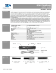
G3 USER’S GUIDE COMBINED RADAR ACTIVATION AND ACTIVE INFRARED SAFETY SENSOR 1 Description Cover 2nd Radar Antenna Radar Motion Sensor Push Buttons IR Presence Sensor IR Prism Radar Antenna Clip Main Connector Radar Tilt Angle Indication 45° 30° 15° IR Curtain Adjustment Screw 2 Specifications DESCRIPTION SPECIFICATION Supply voltage 12 to 24 VAC / VDC: -5% to +10% Power frequency 50 / 60 Hz Power consumption <3W Mounting height • Standard • High 5’9” to 8’2” 8’2” to 13’0” G3 data input 10 to 30 VDC Delay of the output activation after stimulation Transistor : < 1ms 3-color LED • RED: presence detection • GREEN: motion detection • ORANGE: monitoring process Temperature range -30°F to +131°F Degree of protection NEMA 3S / (IP54) Product conformity R&TTE 1999/5/EC & EMC 89/336/EEC BZT Germany, TÜV Dimensions 10.4“ x 2.2“ x 1.9“ Weight .55 lbs / 250 g Housing material ABS & LURAN S Color of Housing Anthracite gray (standard), aluminum, dark bronze, black or white finish Cable length 10’ of 6-conductor cable DESCRIPTION MOTION SENSOR PRESENCE SENSOR Technology Microwave and microprocessor Transmitter frequency: 24.125 GHz Transmitter radiated power: <20 dBm EIRP Transmitter power density: < 5 mW/cm² Focused active infrared and Self-monitored microprocessor Spot diameter (standard): 4” max Number of spots: 24 or 12 spots by curtain Number of curtains: 2 13’0” W x 6’6” D 6’6” W x 8’2” D 6’6” W x 13.75” D 3’3” W x 13.75” D Detection field (standard) • Wide field • Narrow field 75.5640.04 20110726 Page 1 of 15 2 Specifications (Continued) DESCRIPTION MOTION SENSOR PRESENCE SENSOR Detection mode Minimum detection speed 2 inches / sec. (measured in the sensor axis) Response time: < 128ms Angle From 15° to 50° in elevation (adjustable) From - 4° to + 4° (adjustable) Output specification Relay (free of potential change-over contact): • Max contact voltage: 42V AC/DC • Max contact current: 1A (resistive) • Max switching power: 30W (DC) / 60VA (AC) Transistor (optocoupled transistor) • Max output current: 100 mA • Max switching power: 48 VDC Output hold-time 0.5s to 9s (adjustable) 1s (fixed) Manual adjustment • orientation of sensing field (mechanically) • shape of the sensing field (choice of antenna) • multiple functions (using push buttons) • orientation of sensing field • shape of the sensing field (choice of front lens) • multiple functions (by push buttons) Remote control adjustments • Sensitivity • Hold time • Detection mode • Immunity • Output configuration • Immunity • Auto-learn time • Monitoring mode • Number of Curtains • Relay / Output configuration 3 Precautions ! CAUTION Shut off all power before attempting any wiring procedures. Maintain a clean & safe environment when working in public areas. Constantly be aware of pedestrian traffic around the door area. Always stop pedestrian traffic through the doorway when performing tests that may result in unexpected reactions by the door. ESD electrostatic discharge: Circuit boards are vulnerable to damage by electrostatic discharge. Before handling any board ensure you dissipate your body’s charge. Always check placement of all wiring before powering up to insure that moving door parts will not catch any wires and cause damage to equipment. Ensure compliance with all applicable safety standards (i.e. ANSI A156.10 / 19) upon completion of installation. DO NOT attempt any internal repair of the sensor. All repairs and/or component replacements must be performed by BEA, Inc. Unauthorized disassembly or repair: 1. May jeopardize personal safety and may expose one to the risk of electrical shock. 2. May adversely affect the safe and reliable performance of the product will result in a voided product warranty. 4 Pre Installation Check 1. When preparing to wire multiple devices together for a ‘System’ configuration, it is best to ensure the correct operation of each device independently before starting to help reduce troubleshooting time later in the event of a discrepancy. 2. Prior to installing any equipment, ensure the correct line voltage and stability. When applying equipment on a new installation utilizing new electrical supply circuits, always ensure that correct line voltage exists and is stable. Remember to shut the power back off after this is checked and before performing any wiring to the system. 5 Installation 1 Remove Sensor Cover 1. Remove cover from unit by gently prying the tab on the backside of the sensor housing or if the sensor is installed on the header insert a screwdriver behind the unit and gently pry off the cover. Tab Pry Page 2 of 15 75.5640.04 20110726 5 Installation (Continued) 2 Mount Sensor Drill 1/2” wire passage hole anywhere within this area G3 MOUNTING TEMPLATE Drill 1/8” hole 1/4 1/2 3/4 1 1-1/4 1-1/2 1-3/4 2 Do not mount lower than this line Do not mount lower than this line Drill 1/8” hole 1/4 1/2 3/4 1 1-1/4 1-1/2 1-3/4 2 1. Using scale on template, position drawing of sensor on template 0” to 2” from bottom of header. 2. Drill hole marked for wire passage and drill pilot holes for screw mounting. Remove template prior to sensor installation. NOTE: Flush mount with bottom of header is necessary for all negative IR angles. 3. Insert mounting screws approximately halfway in and install the G3 on the screws. When in place, tighten screws to secure to header. NOTE: Leave cover off until mechanical adjustments are complete. 3 Cable Routing 1. With G3 in place, locate the enclosed cable and feed the stripped end through the wire passage hole in the header. 2. Leave enough slack to allow connection to the G3 and proper routing of wire around the plastic post. NOTE: Observe proper routing of the cable as shown. This is to divert rainwater from the G3 if water should run down the cable. Proper routing of the wire also provides easier installation of the cover. Plastic Post Cable / Wire 4 Sensor Wiring 1. When connecting to a microprocessed control box, the motion output and presence output wires may be connected to separate inputs or may also be connected to a mutual input. Some controls may only have an activation input, while others may have an activation input, as well as a safety (or presence) input. Wiring the G3 to an Automatic Door Control with Separate Activation and Safety Inputs O P T I O N 1 Color Microprocessed Controls Red 12 to 24 VAC / VDC: -5% to +10% Black 12 to 24 VAC / VDC: -5% to +10% White Common at Door Control Green Activation Input at Door Control Brown Common at Door Control Blue Safety Input at Door Control Color Controls Without Safety Circuit Red 12 to 24 VAC / VDC: -5% to +10% Black 12 to 24 VAC / VDC: -5% to +10% White Common at Door Control Green Activation Input at Door Control Brown Common at Door Control Blue Activation Input at Door Control Color Controls Without Safety Circuit Red 12 to 24 VAC / VDC: -5% to +10% Black 12 to 24 VAC / VDC: -5% to +10% White Common at Door Control Green Activation Input at Door Control Brown Not Used White and Green provide output for motion and presence detection Blue Not Used On Remote Control Set: W I Z A R D • PWR: Red - 12 to 24 VAC / VDC: -5% to +10% • PWR: Black - 12 to 24 VAC / VDC: -5% to +10% • COM: White - Common at Door Control • ACTIV: Green - Activation at Door Control • COM: Brown - Common at Door Control • SAFETY: Blue - Safety at Door Control For Secondary Activation see important note on page 6. For One Way Evening Mode see addendum 5 on page 15. C O N T R O L Wiring the G3 to an Automatic Door Control with Activation and Safety Wired to One Input O P T I O N 2 W I Z A R D • PWR: Red - 12 to 24 VAC / VDC: -5% to +10% • PWR: Black - 12 to 24 VAC / VDC: -5% to +10% • COM: White - Common at Door Control • ACTIV: Green - Activation at Door Control • COM: Brown - Connected to White Common • SAFETY: Blue - Connected to Green Activation C O N T R O L Brown and Blue may be connected to White and Green Wiring the G3 to an Automatic Door Control with Activation and Safety Signal through Relay Only O P T I O N 3 W I Z A R D • PWR: Red - 12 to 24 VAC / VDC: -5% to +10% • PWR: Black - 12 to 24 VAC / VDC: -5% to +10% • COM: White - Common at Door Control • ACTIV: Green - Activation at Door Control F1 To C O N T R O L 1 75.5640.04 20110726 Page 3 of 15 6 Mechanical Adjustments 1 Radar Motion Sensing Field: Width 0 6.4’ 3.2’ 0 3.2’ 6.4’ 0 3.2’ 3.2’ 6.4’ 6.4’ 9.6’ 6.4’ 9.6’ Wide Pattern 3.2’ 0 3.2’ 6.4’ Narrow Pattern 1. Insert the desired microwave antenna for a wide or narrow field of detection. The optional narrow field antenna is located in the slot behind the mounted antenna as shown. To remove the antenna, carefully remove the protective cover and change the antenna. Once the proper antenna is in place, adjust the angle of antenna as necessary. 2 Radar Motion Sensing Field: Depth 0 6.4’ 3.2’ 0 3.2’ 6.4’ 0 3.2’ 3.2’ 6.4’ 6.4’ 9.6’ 9.6’ 6.4’ 3.2’ 0 3.2’ 6.4’ 0° 15° 45° 30° 15° 30° 45° 13.1’ 1. The position of the sensing field is determined by the vertical angle of the planar antenna. The angle is adjusted by gently rotating the antenna forward or backward. The default angle is 30°. 2. The tilt angle is determined by the position of the sensor with relation to the face of the door. A 15° angle will result in the pattern being drawn back toward the door. A 45° angle will place the pattern further away from the door. Be certain to walk test the detection field and ensure compliance with applicable ANSI standards. 3 IR Presence Sensing Field: Width 7.2’ 7.2’ 3.2’ 14” 14” 6.5’ Wide Pattern Narrow Pattern 1. Install the lens for the desired IR pattern. The wide pattern offers 2 curtains of 24 overlapping spots and the narrow pattern offers 2 curtains of 12 overlapping spots. When installing the lens ensure the smooth part of the lens is installed facing outward. 4 IR Presence Sensing Field: Depth 0° -4° +4° -4° 0° max. 3” max. 3” Sensor Plastic Pin Indicator Sensor Adjustment Screw 1. The IR pattern may be adjusted by moving the pattern nearer or further away from the face of the door by adjusting the tilt angle from +4° to -4°. A counterclockwise rotation of the adjustment screw will move the curtain further away from the door and clockwise rotation will move the curtain toward the door. Precise location of the IR beam may be found by using BEAs Spotfinder P/N 10SPOT. Page 4 of 15 75.5640.04 20110726 7 Remote Control Adjustments 1 Important Remote Control Adjustments Every programming session begins by unlocking the sensor. Thereafter a program setting may be altered by pressing the desired function key followed by the desired value for that function. When all programming is complete press the lock key twice to retain settings. Use the following as a guide: Unlock the sensor to enter into adjustment session (if no access code has been entered) To change the value of a parameter (ex. Maximum duration of presence detection) To check the value of a parameter (ex. maximum duration of presence detection) Lock the adjustment session and go back to normal function 0: No Redirection 1: Transfer Presence Detection To Activation Output (All Relay Output) 2: Activation Output Only Upon Motion and Presence Detection 3: N/A - Future 4: N/A - Future ? 0 (0.5s) → 9 (9s) RED LED Flashes Quickly Enter New Value Select Parameter to Check RED LED Flashes Quickly Press Question Mark RED LED Flashes Slowly ? The Number of Green Flashes Indicate the Value of This Parameter RED LED Flashes Slowly + Lock Code OR Press Lock Key Twice Installation Configuration Radar Motion Detection IR Presence Detection Mounting Height Pulse Frequency Single Unit 1 7 2 5 8 0 3 6 9 F2 1 Low Low A 2 High Low 3 Low High B 4 High High C 5 Low Low 6 High Low D 7 Low High 8 High High Overlapping Units See Important Notes Page 6 0 (min) → 9 (max) default = 7 6.4’ RED LED Flashes Slowly ? Sensitivity 3.2’ Enter New Value + Relay Hold Time 0 RED LED Flashes Quickly Select Parameter to Change F1 Lock 3.2’ Select Parameter to Change 4 Unlock 6.4’ 0-9 F1 Check Value RED LED Flashes Slowly 0-9 … to change any other parameters (ex. Output Configuration) Safety Output Redirection Press Unlock Key 0 3.2’ Door Control 6.4’ 0 3 6 9 F2 1: Normal (LED in Normal Mode) 2: Door Permanently Open (Red LED On) 3: Door Permanently Closed (Red LED Off) Microwave Immunity 9.6’ Microwave Detection Mode 1: Bidirectional Mode 2: Unidirectional Mode 3: Unidirectional Mode with MTF 1: Reduced 2:Normal 3:Increased 4:through 9: Higher number equals higher immunity level. See Important Notes Page 6 75.5640.04 20110726 Page 5 of 15 7 Remote Control Adjustments (Continued) 2 Important Remote Control Adjustments Radar Motion Detection IR Presence Detection External Monitoring SMR Important Notes • Defaults are Shown in Bold Print • Restore Factory Defaults Magic Wand + 9 Sensor will Self Launch Set Up • Quick Set Up has Two Second Duration • Assisted Set Up is recommended for first time set up. Duration is 16 seconds and will automatically trigger door to open position during set up routine. Microwave Immunity: Immunity levels above 3 are intended for applications where excessive interference may be causing unintended detection. When applying a value of 4 or higher increment the value one step at a time followed by a walk test. When complete, ensure compliance with all applicable safety and performance standards. 1 2 3 A 4 5 6 B 7 8 9 C F1 0 F2 D + ? Secondary Activation Sensitivity 6.4’ 3.2’ 0 3.2’ 6.4’ 0 3 3.2’ 6 9 6.4’ 9.6’ Automatic Learn Time Reset access code to default: Power cycle the sensor and within 60 sec. press unlock, lock, 0000. 3 1: 1 Curtain (Safety Curtain Close to the Door) 2: 2 Curtains 3:2nd Curtain in Dynamic Mode (Enabled After a Motion Detection) 0 Installation Configuration: To prevent crosstalk when installing overlapping units set one unit to 5 and one unit to 7 for Low mount or one unit to 6 and one unit to 8 for High mount. 1: Normal 2: High (extreme snow, rain, pedimats or lighting) See Important Notes Number of IR Curtains 0 (min) → 9 (max) default = 0 Secondary Activation: On a one-way traffic application, use a toggle switch or other switch to break the green wire to door control. Door control safety circuit must turn off in door closed position. Infrared Immunity 0: Monitoring Disabled (Off) SMR (Off) 1: Monitoring Enabled (On) SMR (On) 0: 30 Seconds 4: 10 Minutes 1: 1 Minute 5: 20 Minutes 2: 2 Minutes 6: 60 Minutes 3: 5 Minutes 9: Infinity No Learn Output Configuration Setup Launch Quick Setup 0 9 Launch Assisted Setup Restore Factory Settings Note: F1 function and the access code are not reset. Motion Out Presence Out 1 Active / N.O. Passive / N.C. 2 Passive / N.C. Active / N.O. 3 Passive / N.C. Passive / N.C. 4 Active / N.O. Active / N.O. Launch Set Up of Infrared Curtains Unlock the sensor to enter into adjustment session To Launch an Assisted Set Up → Required after mechanical adjustments of the IR sensor module → Required once after first installation Press Unlock Key RED LED Flashes Slowly 0 Press Set Up Press 0 RED / GREEN LED Alternating Flashes The sensor performs a door opening and closing cycle to check the influence of the door leaves to the safety curtains. See Troubleshooting if RED LED flashes quickly after set up. Page 6 of 15 75.5640.04 20110726 8 Manual Set Up Without Remote 1 Manual Set Up Set up of the G3 may be accomplished by the use of two G3 mounted programming buttons. The procedures below indicate how to program using these buttons. NOTE: Red LED indicates parameter. Green LED indicates value. Program Buttons To begin programming: Briefly press the right button and move away from the sensing zones. To reset the unit to factory defaults: Press and hold both buttons simultaneously until both Red and Green LEDs flash alternately. NOTE: F1 function and the access code are not reset after pressing the manual program buttons. To customize the settings from factory defaults: To enter the customizing mode: Press the right button until the LED flashes and then release. To return to standard mode: Press the right button again until the LED stops flashing and then release. Customizing Mode: • The Red LED light indicates the number for the parameter being altered (1 flash = parameter #1). • The Green LED light indicates the value for the parameter being altered (1 flash means value = 1). • The Right Button enables selection of the parameter number being altered (+1 for each press). • The Left Button enables alteration of the parameter (+1 for each press). Helpful Hint: When the sensor is wired correctly pressing and holding the left button will result in disconnecting all outputs from that sensor, allowing the door to close, if no other devices are being activated. PARAMETER NUMBER (Altered by the right button and confirmed by RED LED) PARAMETER VALUES (Altered by the left button and confirmed by GREEN LED) DEFAULT VALUE 1 Radar Sensitivity 0-9 7 2 Relay hold time 0-9 0 3 Output configuration 1-4 4 4 Auto-learn presence sensing 0-9 0 5 Detection mode 1- 4 3 6 Microwave Immunity 1-9 3 7 IR Immunity 1-3 1 8 Not Used Displays 8 Orange Flashes Displays 8 Orange Flashes 9 Not Used 0 0 10 IR curtain 1-3 3 11 Secondary Sensitivity 0-9 0 12 Height & Frequency 1-4 1 13 Output Re-Direction 0-4 0 14 Door Control Function 1-3 1 15 Not Used Displays 15 Orange Flashes Displays 15 Orange Flashes EXAMPLE: Change radar sensitivity from 7 to 9 and set hold time to 4 seconds: NOTE: When the highest value for the parameter has been reached, the value will “roll over” to its lowest value (e.g. for radar mode: 1, 2, 3, then 1, 2, …). The sensor automatically returns to standard mode if neither button has been pressed for one minute. REQUIRED: If the IR frequency has been manually changed, to prevent the sensors from being in permanent detection, momentarily depress the right program button to launch an assisted setup. Press the right button for 2 seconds, you will enter the customizing mode: • The red LED flashes once (parameter 1) • The green LED flashes 7 times (sensitivity = 7) •Press the left button twice to move from sensitivity = 7 to sensitivity = 9 Press the right button once to move to Parameter 2 (relay hold time): • The red LED flashes twice (parameter 2) •The green LED does not flash (hold time = 0 seconds) •Press the left button four times to move from hold time = 0 to hold time = 4 seconds 75.5640.04 20110726 Page 7 of 15 9 Power Up 1 Power Up Procedures STEP USER’S ACTION RESULT Step 1 With all wiring in place, apply power to door control and 12 to 24 VAC / VDC: -5% to +10% to G3. Once powered, observe LED status on the G3. Stop all traffic through the doorway while performing this step, and remain clear of the G3’s detection zones. The G3 will show a steady red LED during the set-up procedure. Once the G3 completes setup, the door will close and begin normal operation thereafter. Setup process takes approximately 6 seconds, if uninterrupted. Step 2 If the sensor is being powered for the first time, because of new installation or sensor is being replaced, unlock the G3 and Press the Magic Wand Key, followed by a number 0. Observe the LED status during setup. • NO LED UPON COMPLETION = Successful setup •RED LED ON = Presence being detected -G3 is seeing an object. •GREEN LED MOMENTARILY ON = MOTION DETECTION (G3 sees movement). Adjust microwave functions: angle, sensitivity, immunity. •ORANGE LED ON = Possible fault. If LED stays on, reset power and observe LED. If it comes back on steady, replace G3. •Fast flashing Red = setup failed due to improper IR curtain adjustment or disturbance of IR curtain during setup. Once set-up is complete, the LED indication will reflect the status of the set-up. Observe the LED while standing outside of the detection zones. Step 3 Proceed with fine tuning the mechanical , as well as the program adjustments of the G3. Refer to the applicable sections of this manual for altering any settings. Be sure to check: • Motion width & depth • Presence width & depth •Position of infrared curtain • Sensitivity of motion field Sensor must always be adjusted to be in compliance with the current version of ANSI A156.10. 10 Troubleshooting 1 Troubleshooting Procedures PROBLEM PROBABLE CAUSE CORRECTIVE ACTION Orange LED is illuminated on G3. 1.G3 IR is in saturation 2.Internal fault within the G3 3.Faulty Power Input 1.Launch a new setup and remain all clear from the detection area. 2.Remove power, then re-apply. Input power may have fluctuated beyond tolerances. Red LED flashes after attempting a set-up. 1.Infrared curtains are too close to the door and the sensor detects a door influence. 2. IR curtain too far away from door. 3. IR curtain disturbed during setup. 1.Adjust Infrared curtain as necessary. Use of BEA’s Spotfinder during this process is recommended. 2. Adjust Infrared curtain as necessary. Use of BEA’s Spotfinder during this process isrecommended. 3. Relaunch a setup and keep people away from door until setup completes. Door will not close Red LED off at G3. 1.On-Off switch at door control in wrong position or is faulty. 2.Improper Relay Configuration on G3. 3.Faulty door control. 1.Check to insure On-Off switch for door is in the ON or AUTOMATIC position. If switch is in correct position, check switch with multi-meter for proper operation. 2.Insure correct polarity at Brown and Blue wires 3.Check Relay Configuration setting on each G3. Refer to page 6 for settings. 4.Remove all sensor inputs from the door control. If door remains open, fault exists with door control or motor. Refer to manufacturer’s manual for further troubleshooting. If door closes with sensor inputs removed, fault exists with sensors or related wiring. Page 8 of 15 75.5640.04 20110726 10 Troubleshooting (Continued) 1 Troubleshooting Procedures PROBLEM PROBABLE CAUSE CORRECTIVE ACTION Door opens when it should close. 1.Relay Configuration on wrong setting. 1.Check Relay Configuration setting. Door will not open. 1.On-Off switch at door control in wrong position or is faulty. 1.Check to insure On-Off switch for door is in ON or AUTOMATIC position. If it is in correct position, check switch with multi-meter for proper operation. Door will not open (Continued). 1.G3 not detecting traffic. 2.Faulty wiring between sensor and door control. 3.Faulty door control. 1.Walk in and out of G3 detection area, if green LED does not illuminate check: a. Power supply for G3: 12 to 24 VAC / VDC: -5% to +10% b. Check G3 setting on each G3. c. Check Relay Configuration for each G3. 2.Remove all sensor inputs from the door control. Jumper the common and activate terminals of the door control. If door does not open, fault lies within door control or motor. Refer to manufacturer’s manual for further troubleshooting. If door opens, fault lies with sensors or related wiring. 3.Refer to Step 2. Door keeps recycling open. 1.G3 is seeing door. 2.G3 is seeing movement from unwanted objects. 3.Vibration is triggering the G3. 1.Observe LED status on each G3. Green LED indicates motion detection, red LED indicates presence. If LED’s are on, make sensor adjustments as necessary to eliminate unwanted detection. Check angle, sensitivity, and immunity for presence and motion. 2.Check for moving objects in the path of detection, such as posters, banners, etc. 3.Locate source of vibration and correct as necessary. G3 will not respond to remote control. 1.Batteries in remote are dead or are installed improperly. 1.Ensure batteries are installed correctly. Replace batteries: AAA 1.5 volt. G3 will not unlock when access code is entered. 1.Improper code being entered. 1.Reset code to the default value of 0000 by performing the following: a. Cut and restore power supply. No code is required to unlock during the first minute after powering. Reset code prior to locking. 11 ANSI / AAADM Compliance AAADM American Association of Automatic Door Manufactures Upon finishing the installation and/or service work perform at a minimum a daily safety check in accordance with the minimum inspection guidelines provided by AAADM. Provide each owner with an owner’s manual that includes a daily safety checklist and contains at a minimum the information recommended by AAADM. Offer a familiarization session with the owner explaining how to do daily inspections and calling out location of cutoff switches to put equipment out of service if a deficiency is noted. The equipment should be inspected in accordance with the minimum inspection guidelines annually. A safety check that includes at a minimum the items listed on the safety information label must be performed during each service call. If you are not an AAADM certified inspector BEA strongly recommends to have an AAADM certified inspector perform an AAADM inspection and placing a valid inspection sticker below the safety information label prior to placing the equipment into operation. 75.5640.04 20110726 Page 9 of 15 12 Accessories Universal Rain Cover 10URC Ceiling Adapter 10WCA Weather / Rain Cover 10WRC Spotfinder 10SPOT Cable Adapter 10IFBWIZARDII 13 Company Contact Do not leave problems unresolved. If a satisfactory solution cannot be achieved after troubleshooting a problem, please call BEA, Inc. If you must wait for the following workday to call BEA, leave the door inoperable until satisfactory repairs can be made. Never sacrifice the safe operation of the automatic door or gate for an incomplete solution. Our Service Technicians can be called 24 hours a day, 7 days a week. For more information visit www.beasensors.com. Phone: 1-800-523-2462 Fax: 1-888-523-2462 After Normal Business Hours West / Mexico 1-888-419-2564 Central 1-800-407-4545 AK, MI, WI, TX, Canada 1-866-836-1863 East 1-866-249-7937 Page 10 of 15 75.5640.04 20110726 1 2 3 4 RB WH RB BL EB WH EB BL ON 1 2 3 4 5 4 3 2 1 MICROCELL ONE NC NO COM 12-24 VAC/DC 12-24 VAC/DC SAFETY blue COM brown ACTIVATION green COM white POWER black POWER red IF AFTER TROUBLESHOOTING A PROBLEM, A SATISFACTORY SOLUTION CANNOT BE ACHIEVED, PLEASE CALL B.E.A., INC. FOR FURTHER ASSISTANCE DURING EASTERN STANDARD TIME AT 1-800-523-2462 FROM 8AM - 5PM. FOR AFTER-HOURS, CALL EAST COAST: 1-866-836-1863 OR 1-800-407-4545 / MID-WEST: 1-888-308-8843 / WEST COAST: 1-888-419-2564. DO NOT LEAVE ANY PROBLEM UNRESOLVED. IF YOU MUST WAIT FOR THE FOLLOWING WORKDAY TO CALL B.E.A., LEAVE THE DOOR INOPERABLE UNTIL SATISFACTORY REPAIRS CAN BE MADE. NEVER SACRIFICE THE SAFE OPERATION OF THE AUTOMATIC DOOR OR GATE FOR AN INCOMPLETE SOLUTION.WEB: WWW.BEASENSORS.COM SEE NOTE 2 COMMON EXTERIOR SCAN COMMON INTERIOR SCAN 75.5640.04 20110726 A SIZE: REV BY: TUC DATE: 24 NOV 2005 DRAWN BY: KJG SCALE: NONE 1 OF 1 SHEET PART NO: 100 ENTERPRISE DRIVE PITTSBURGH, PA 15275 PHONE: (412) 249-4100 FAX: (412) 249-4101 EMAIL: www.beasensors.com 1 2 3 4 5 6 7 8 TB- 2 80.0123.04 BEAMS 1 2 3 COMMON 4 5 6 7 8 HOLDING TB- 3 DURAGLIDE INTERFACE BOARD TITLE: STANLEY DURAGLIDE WITH WIZARD II /G3 SYSTEM, MICROCELL SAFETY blue COM brown ACTIVATION green COM white POWER black POWER red NOTES: 1) WIZARDS WILL OPERATE WITH THE 12 VDC ON PINS 1&2, 5&6. 2) ONE WAY FUNCTION IS APPLICABLE IF CLOSED DOOR MONITORING SWITCH IS INSTALLED. SWITCH SHALL CLOSE 2" FORM FULL CLOSE 1 2 3 4 RA WH RA BL EA WH EA BL * RECEIVER (A), EMITTER (A) RECEIVER (B), EMITTER(B) WH= WHITE, BL= BLACK 24 V TRANSFORMER EXTERIOR WIZARD/G3 Addendum 1 Page 11 of 15 1 2 3 4 RB WH RB BL EB WH EB BL ON 1 2 3 4 5 4 3 2 1 MICROCELL ONE NC NO COM 12-24 VAC/DC 12-24 VAC/DC SAFETY blue COM brown ACTIVATION green COM white POWER black POWER red SAFETY blue COM brown ACTIVATION green COM white POWER black POWER red Page 12 of 15 IF AFTER TROUBLESHOOTING A PROBLEM, A SATISFACTORY SOLUTION CANNOT BE ACHIEVED, PLEASE CALL B.E.A., INC. FOR FURTHER ASSISTANCE DURING EASTERN STANDARD TIME AT 1-800-523-2462 FROM 8AM - 5PM. FOR AFTER-HOURS, CALL EAST COAST: 1-866-836-1863 OR 1-800-407-4545 / MID-WEST: 1-888-308-8843 / WEST COAST: 1-888-419-2564. DO NOT LEAVE ANY PROBLEM UNRESOLVED. IF YOU MUST WAIT FOR THE FOLLOWING WORKDAY TO CALL B.E.A., LEAVE THE DOOR INOPERABLE UNTIL SATISFACTORY REPAIRS CAN BE MADE. NEVER SACRIFICE THE SAFE OPERATION OF THE AUTOMATIC DOOR OR GATE FOR AN INCOMPLETE SOLUTION.WEB: WWW.BEASENSORS.COM NOTE: 1) DO NOT CONNECT BROWN WIRES TO C-SWITCH COMMON. 2) OBSERVE POLARITY WITH BROWN CONNECTING TO GROUND (0 VDC). 3) A JUMPER MUST BE INSTALLED IN PINS 9,12 ON CONTROL BOX FOR RE-ENTRY SENSOR IN ONE-WAY TRAFFIC AS PER APPLICABLE ANSI STANDARD. 1 2 3 4 RA WH RA BL EA WH EA BL * RECEIVER (A), EMITTER (A) RECEIVER (B), EMITTER(B) WH= WHITE, BL= BLACK 24 V TRANSFORMER EXTERIOR WIZARD/G3 } LOCKING DEVICE OUTER IMPULSE INNER IMPULSE + 18 VDC STOP IMPULSE PRES. IMPULSE(1) C-SWITCH, 0 VDC PRES. IMPULSE(2) + 18 VDC PARTIAL OPEN EXIT OFF RESET * A SIZE: REV BY: KJG DATE: 13 JUL 2005 DRAWN BY: KJG SCALE: NONE 1 OF 1 SHEET PART NO: 80.0058.04 TITLE: BESAM CUD/J-9 AMD2 SLIDING DOOR WITH WIZARD II / G3 SYSTEM 100 ENTERPRISE DRIVE PITTSBURGH, PA 15275 PHONE: (412) 249-4100 FAX: (412) 249-4101 EMAIL: www.beasensors.com R 1 2 3 4 5 6 7 8 9 10 11 12 13 14 15 16 AMD2 CONTROL * Optional - connect to reset (TB1 R) if required. Addendum 2 75.5640.04 20110726 SAFETY blue COM brown ACTIVATION green COM white POWER black POWER red SAFETY blue COM brown ACTIVATION green COM white POWER black POWER red IF AFTER TROUBLESHOOTING A PROBLEM, A SATISFACTORY SOLUTION CANNOT BE ACHIEVED, PLEASE CALL B.E.A., INC. FOR FURTHER ASSISTANCE DURING EASTERN STANDARD TIME AT 1-800-523-2462 FROM 8AM - 5PM. FOR AFTER-HOURS, CALL EAST COAST: 1-866-836-1863 OR 1-800-407-4545 / MID-WEST: 1-888-308-8843 / WEST COAST: 1-888-419-2564. DO NOT LEAVE ANY PROBLEM UNRESOLVED. IF YOU MUST WAIT FOR THE FOLLOWING WORKDAY TO CALL B.E.A., LEAVE THE DOOR INOPERABLE UNTIL SATISFACTORY REPAIRS CAN BE MADE. NEVER SACRIFICE THE SAFE OPERATION OF THE AUTOMATIC DOOR OR GATE FOR AN INCOMPLETE SOLUTION.WEB: WWW.BEASENSORS.COM NOTES: 1) DO NOT CONNECT BROWN WIRES TO C-SWITCH COMMON. 2) OBSERVE POLARITY WITH THE BROWN WIRE CONNECTED TO GROUND (0 VDC). 3) A JUMPER MUST BE INSTALLED BETWEEN PINS 5, 12 ON THE CONTROL BOX TO ALLOW FOR RE-ENTRY SENSOR IN ONE-WAY TRAFFIC MODE TO COMPLY WITH ANSI A156.10 SECTION 8.3.3. 4) CAN POWER SENSOR FROM CONTROL BOX 5) IF REPLACING ULTRAVIEWS W/ WIZARDS SET DIP SW. #7 TO OFF. 24 V TRANSFORMER 16 15 14 13 12 11 10 9 8 7 6 5 4 3 2 1 100 ENTERPRISE DRIVE PITTSBURGH, PA 15275 PHONE: (412) 249-4100 FAX: (412) 249-4101 EMAIL: www.beasensors.com INNER IMPULSE - 0 VDC + 24 VDC MONITORED SAFETY/ONLY PHOTOCELL C-SWITCH/MONITORED INNER IMPULSE STOP IMPULSE PRESENCE IMPULSE 2 PRESENCE IMPULSE 1 - 0 VDC + 24 VDC SYNCHRONIZING OUTPUT SYNCHRONIZING INPUT KEY IMPULSE OUTER IMPULSE - 0 VDC + 24 VDC UNISLIDE CONTROL 75.5640.04 20110726 A SIZE: REV BY: TUC DATE: 30 NOV 2005 DRAWN BY: KJG SCALE: NONE 1 OF 1 SHEET PART NO: 80.0163.04 TITLE: BESAM UNISLIDE SLIDING DOOR WITH WIZARD II / G3 SYSTEM EXTERIOR WIZARD II/G3 Addendum 3 Page 13 of 15 1 2 3 4 RB WH RB BL EB WH EB BL ON 1 2 3 4 5 4 3 2 1 MICROCELL ONE NC NO COM 12-24 VAC/DC 12-24 VAC/DC SAFETY blue COM brown ACTIVATION green COM white POWER black POWER red Page 14 of 15 IF AFTER TROUBLESHOOTING A PROBLEM, A SATISFACTORY SOLUTION CANNOT BE ACHIEVED, PLEASE CALL B.E.A., INC. FOR FURTHER ASSISTANCE DURING EASTERN STANDARD TIME AT 1-800-523-2462 FROM 8AM - 5PM. FOR AFTER-HOURS, CALL EAST COAST: 1-866-836-1863 OR 1-800-407-4545 / MID-WEST: 1-888-308-8843 / WEST COAST: 1-888-419-2564. DO NOT LEAVE ANY PROBLEM UNRESOLVED. IF YOU MUST WAIT FOR THE FOLLOWING WORKDAY TO CALL B.E.A., LEAVE THE DOOR INOPERABLE UNTIL SATISFACTORY REPAIRS CAN BE MADE. NEVER SACRIFICE THE SAFE OPERATION OF THE AUTOMATIC DOOR OR GATE FOR AN INCOMPLETE SOLUTION.WEB: WWW.BEASENSORS.COM 100 ENTERPRISE DRIVE PITTSBURGH, PA 15275 PHONE: (412) 249-4100 FAX: (412) 249-4101 EMAIL: www.beasensors.com 1 2 3 4 5 6 7 8 9 10 11 12 13 14 15 16 DAY/NITE SW +24VDC INTERIOR SW EXTERIOR SW COMMON + 24VDC SAFETY BEAM COMMON TOGGLE SW COMMON CLS MON SW COMMON PARTIAL OPEN 2WAY/ 1 WAY NIGHT SW COMMON C2150 CONTROL A SIZE: REV BY: KJG DATE: 18 OCT 2005 DRAWN BY: KJG SCALE: NONE 1 OF 1 SHEET PART NO: 80.0105.03 TITLE: HORTON C2150 CONTROL BOX WITH WIZARD II / G3 SYSTEM, MICROCELL 1 INTERIOR WIZARD II/G3 SAFETY blue COM brown ACTIVATION green COM white POWER black POWER red NOTE: 1) WIZARDS AND MICROCELL 1 WILL OPERATE WITH THE 24 VAC ON THE C3925 POWER SUPPLY. 1 2 3 4 RA WH RA BL EA WH EA BL * RECEIVER (A), EMITTER (A) RECEIVER (B), EMITTER(B) WH= WHITE, BL= BLACK 24 V TRANSFORMER EXTERIOR WIZARD II/G3 Addendum 4 75.5640.04 20110726 Addendum 5 Did you know? The G3 has two simple choices for active infrared immunity, Normal and High. High immunity may be used in highly reflective applications or in extreme cases of snow, rain, pedimats or lighting. Intelli-tracking, which is built into the G3’s core software, reduces challenges and service calls in the field! One way night mode / secondary activation, can be used to meet ANSI for activation at 43” and then at 24” with a flip of a switch by the end user. W I Z A R D • PWR: Red - 12 to 24 VAC / VDC: -5% to +10% • PWR: Black - 12 to 24 VAC / VDC: -5% to +10% • COM: White - Common at Door Control • ACTIV: Green - Activation at Door Control • COM: Brown - Common at Door Control • SAFETY: Blue - Safety at Door Control C O N T R O L One way evening mode: Switch on ACTIVATION Line! One way night mode / secondary activation: Activation has two zones (i) inner zone with 24” adjustable pattern depth which outputs on the safety circuit (brown and blue wires); (ii) outer full zone with 43” adjustable pattern depth which outputs on the activation circuit (white and green wires). By cutting the activation circuit with a switch, only the inner 24” zone is active. Because this is on the safety circuit, the inner zone is only active when the door is in-motion or open. When performing service the G3 can hold the door permanently open using the F2 function. The G3 is for use in all of North America. No special part numbers for Canada are needed. 1 2 3 A 4 5 6 B 7 8 9 C F1 0 F2 D + To change to “High” Infrared Immunity press: 2 To hold the door open during service press: F2 2 ? To set the sensor to normal state press: F2 1 75.5640.04 20110726 Page 15 of 15