1
MASTERPACT® Universal Power
Circuit Breaker
Class 631
CONTENTS
Description
Page
Introduction ............................................................................................................... 1
Advantages ............................................................................................................... 3
Description ................................................................................................................ 6
Control Units ............................................................................................................. 7
Accessories ............................................................................................................. 23
Switch ..................................................................................................................... 36
Trip Curves ............................................................................................................. 37
Wiring Diagrams ..................................................................................................... 42
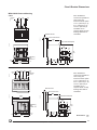
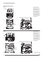
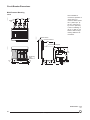
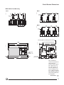
Circuit Breaker Dimensions .................................................................................... 46
Appendix ................................................................................................................. 62
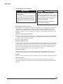
Introduction
Standard Compliance
n UL489: MP08 to MP50 circuit breakers and their accessories are Listed under UL files E63335,
E103955 and E113555
n UL1066/ANSI: MC08 to MC50 circuit breakers are UL Listed according to UL1066 (ANSI C37-13)
under file E161835
n International Standards: the MASTERPACT® circuit breaker has been designed to meet all the
major standards including:
IEC 947-2 and related standards such as VDE, BS, EN, etc.
o JEC, JIS
n UL 1008: MP12, MP20 and MP30 circuit breakers are suitable for use in transfer switch
equipment
n Marine Applications:
o Homologated by Bureau Veritas
o Approved by Det Norske Veritas and Germanische Lloyd's
o Listed by Lloyd's Register of Shipping
o American Bureau of Shipping application
o UL marine
o
High Short-time Current Rating: Up to 100 kA for 1 sec.
The exceptional short-time rating of 75,000 A in a 3000 A frame and 100,000 A in a 4000 A frame
and above allows the circuit breakers to be fully selective up to their interrupting ratings.
100% Rated
The circuit breakers are designed for continuous operation at 100% of their current rating.
Other Performances
The UL 489 and UL1066 (ANSI C37-13) standard performance tests assure that the circuit breaker
has sufficient characteristics to be used in normal conditions. However, the circuit breaker exceeds,
without additional costs, the UL standard 1,500 operations required in endurance. The heavy-duty
mechanism and the contact design provide a mechanical endurance of 10,000 operations (approx.)
without maintenance (see page 64).
Tropicalization
The standard moisture and fungus protection ensure normal operation under extreme ambient
conditions. MASTERPACT circuit breakers comply with T2 tropicalization (IEC Standard 68-2-30);
relative humidity 95% at 113°F (45°C) and 80% at 131°F (55°C) (hot, humid climate). Salt spray
resistance as per IEC 68-2-11.
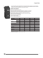
Poles
The 4-pole version is an efficient solution to ground fault problems created by incorrectly grounded
standby generators and incorrect transfer switching systems. By isolating the neutral of multiple
sources coupled together, 4-pole circuit breakers prevent ground faults from returning to the source
via unintended paths. Where unintended paths exist, ground fault sensing can become inaccurate or
create nuisance tripping.
Ampere Rating (A)
3-Pole
4-Pole
800
MP-MC
MP-MC
1200
MP
MP
1600
MP-MC
MP-MC
2000
MP-MC
MP-MC
2500
MP
MP
3000
MP
MP
3200
MC
4000
MP-MC
MP (1)
5000
MP-MC
MP (1)
6300
MP (1)
(1) Not UL Listed.
1
11/98
©1995 Square D—All Rights Reserved
Introduction
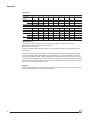
Ratings
Type
Ampere Rating (A)
MP/MC08
800
Sensor Ratings (A)
250–400–600–800
MP12
1200
800–1200
MP/MC16
1600
1200–1600
MP/MC20
2000
1600–2000
MP25
2500
2000–2500
MP30
3000
2500–3000
MC32
3200
2500–3200
MP/MC40
4000
2500–3000–4000
MP/MC50
5000
4000–5000
MP63
6300
5000–6300
Interrupting Ratings
UL489/NEMA AB1
Type
Rating (A)
480 Vac
600 Vac
Short-time
Standard Interrupting Rating
MP08 H1
800
65 kA
65 kA
50 kA
MP12 H1
1200
65 kA
65 kA
50 kA
MP16 H1
1600
65 kA
65 kA
50 kA
MP20 H1
2000
75 kA
75 kA
75 kA
MP25 H1
2500
75 kA
75 kA
75 kA
MP30 H1
3000
75 kA
75 kA
75 kA
MP40 H1
4000
100 kA
100 kA
100 kA
MP50 H1
5000
100 kA
100 kA
100 kA
MP63 H1
6300 (1)
100 kA
100 kA
100 kA
High Interrupting Rating
MP08 H2
800
100 kA
65 kA
50 kA
MP12 H2
1200
100 kA
65 kA
50 kA
MP16 H2
1600
100 kA
65 kA
50 kA
MP20 H2
2000
100 kA
75 kA
75 kA
MP25 H2
2500
100 kA
75 kA
75 kA
MP30 H2
3000
100 kA
75 kA
75 kA
MP40 H2
4000
125 kA
100 kA
100 kA
MP50 H2
5000
125 kA
100 kA
100 kA
MP63 H2
6300 (1)
150 kA
100 kA
100 kA
508 V
635 V
Short-time
(1) Not UL Listed.
UL1066/ANSI C37–13/NEMA SG3
Type
Rating (A)
Special Interrupting Rating
MC08 N1
800
50 kA
50 kA
42 kA
MC16 N1
1600
50 kA
50 kA
50 kA
Standard Interrupting Rating
MC08 H1
800
65 kA
65 kA
50 kA
MC16 H1
1600
65 kA
65 kA
50 kA
MC20 H1
2000
65 kA
65 kA
65 kA
MC32 H1
3200
65 kA
65 kA
65 kA
MC40 H1
4000
100 kA
100 kA
100 kA
MC50 H1
5000
100 kA
100 kA
100 kA
2
©1995 Square D—All Rights Reserved
11/98
Advantages
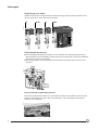
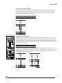
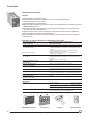
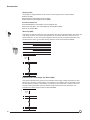
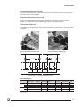
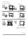
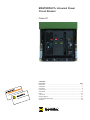
Drawout Circuit Breaker Design
n The drawout assembly mechanism allows the circuit breaker to be racked in four positions
(connected, test, disconnected and withdrawn).
n The closing and opening push buttons, the racking handle and racking mechanism are accessible
06313005
06313004
06313003
through the front door cutout. Therefore the circuit breaker can be disconnected without opening
the door and accessing live parts. Safety shutters can be provided as an option for protection from
live parts when the circuit breaker is removed.
Connected Position
Test Position
Disconnected Position
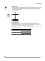
True Two-step Stored Energy Mechanism
The closing time is less than five cycles. The circuit breaker is operated via a stored-energy
mechanism which can be manually or motor charged. Closing and opening operations can be initiated
either from the local push buttons on the circuit breaker front face or by remote control.
O–C–O cycle is possible without recharging.
Designed for No Maintenance...
The circuit breaker has fewer parts (by a factor of at least five) than conventional circuit breakers
while performing the same functions. This leads to greatly enhanced reliability and reduction in
maintenance. Under normal operating conditions, according to standards and controlled by tests, the
circuit breaker does not require maintenance.
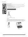
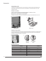
…But Exceeds Standards with an Easy and Reduced Maintenance
06313006
06313007
It is easy to remove the arc chutes and visually inspect the contacts and wear indicator. The operation
counter (spring-charging motor option) can also indicate when inspections and possible maintenance
should be done. After operating conditions exceeding those given by standards, it is possible to
extend the circuit breaker life by:
n Replacement of arc chutes and spring charging motor by the user.
n Replacement of main contacts by an after sale service team.
Note: See pages 62–63 for additional information.
Contact Good
(Circuit Breaker Closed)
Contact Worn
(Circuit Breaker Closed)
3
11/98
©1995 Square D—All Rights Reserved
Advantages
Single Design up to 6300 A
All frame sizes have been designed with the same technology featuring identical depth and door
cutouts, and common control units and accessories.
40-50
32
08-30
06313008
63
IG
LI
L
G
off
LIG
I
reset V
push to reset
LG
masterpact
I
O
I3
I2
I1
90%
push OFF
I
push ON
STR 58 U
tr
Ir
.92
.95 60
.9
.88
Io=3000A
%Ir
.98 30
.85
1
.8
xIo
cat. no. 54775
for masterpact
with sensors
Im
5
4
3
2
1.5
I
Ir fault
6
.3
8
.2
frame size 2000A
12
off
O OPEN
240
th :
.2
.1
0
off
Ih
600
800
500
th
T
th .4
.4
.3
.3
1000 .2
320
250
I
i
+S–
.95
.7
.98
.6
.2
.1
off
R
Ic2.8
.93
.85
.9
.86
.8
–T+
.1
2
on I t
1200
A
Ic1 .9
.85
test
N° LM-8792
22
400
Im fault
tm
fault
Doles. Issue
NEMA
interrupting rating
amps
max RMS sym
Amps
Volts
100K
240
100K
480
65K
600
.3
17
xIn
tr
Ih
E63335
List.
UND. LAB. O
CIRCUIT BREAKER
00000
480
15
at 1,5Ir
.1
2
on I t
10
xIo
8
2
6
4
Im :
120
tm.4
In = 6000A
Ir :
t
F
circuit breaker
3 pole
600V 50/60Hz
discharged
20%
90
105
M08 H2
operation
cubical
suitable for continious
in a minimum
inches
at 100% rating
by W21 by D14.1/4
space H17.5 not required
ventilation is
50%
1
xIr
.95
1
.5
xIr
690V 50/60Hz
IEC 957-2 rating
interrupting
75KA
Icu 380/440V
75KA
660V
75KA
Icu 380/440V
75KA
660V
short time rating
sec.
Icw=75KA 0.5
test
connected
test
disconnected
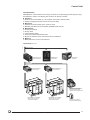
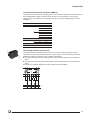
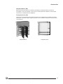
Field-installable Accessories
n As the installation develops and changes, the circuit breaker can develop and change with it.
06313009
Most accessories are field-installable, without losing the UL Listing mark, without any adjustment
and with only the aid of a screwdriver.
n The uniform design of the circuit breaker line allows these accessories to be common for the
whole line.
Front Connection of Secondary Circuits
06313010
All accessory terminals are located on a connecting block which is accessible from the front even
with the circuit breaker in the test or disconnected position. This is particularly useful for field
inspection and modification.
4
©1995 Square D—All Rights Reserved
11/98
Advantages
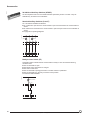
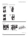
Disconnecting through Door
The racking handle and racking mechanism are accessible through the front door cutout.
Disconnecting the circuit breaker will therefore be possible without opening the door and giving
access to live parts.
Isolation Function by Positive Indication of Contact Status
The mechanical indicator is truly representative of the status of all three main contacts.
Segregated Compartment
Once the front cover has been removed to provide access to the auxiliary compartment, the main
contacts remain fully isolated. Furthermore, interphase partitioning allows full insulation between
each pole even if the front cover has been removed.
Reinforced Insulation
06313011
Two insulation barriers separate the front of the circuit breaker from main circuits.
5
11/98
©1995 Square D—All Rights Reserved
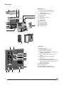
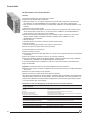
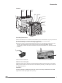
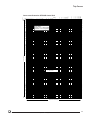
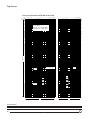
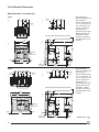
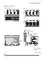
Description
2
Description
3
06313012
1
4
5
13
12
6
11
1. Arc chamber and terminal covers
2. Accessories and control unit front
connecting block
3. Position carriage switches
4. Opening coils
5. Arc chute
6. Spring charging motor
7. Front cover
8. Control unit
9. Racking crank
10. Pull-out handgrip
11. Retractable rails
12. Handling handgrip
13. Safety shutters
10
9
8
11
7
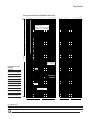
Front View
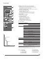
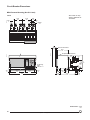
1.
2.
3.
4.
06313013
12
IG
LI
L
G
off
LIG
I
reset V
push to reset
LG
1
LIN GERIN
MER
masterpact
I
O
I3
I2
I1
push OFF
90%
I
MP20
H1
r
circuit breake
3 pole
z
600V 50/60H
push ON
STR 58 U
frame size 2000A
operation
cubical
suitable for continious
in a minimum
inches
at 100% rating
by W21 by D14.1/4
space H17.5 not required
ventilation is
50%
O
OPEN
20%
tr
Ir
Io=3000A
90
%Ir
105
.92
.95 60
.9
.88
.98 30
.85
1
.8
xIo
cat. no. 54775
for masterpact
with sensors
5
4
Ir :
t
Ir fault
8
.1
0
off
4
Ih
600
800
500
th
400
i
+S–
1200
A
Ic1 .9
.4
.3
.3
z
690V 50/60H
IEC 957-2 rating
interrupting
75KA
Icu 380/440V
75KA
660V
75KA
Icu 380/440V
75KA
660V
rating
short time
sec.
Icw=75KA 0.5
.2
.1
.1
2
on I t off
.8
–T+
R
Ic2.8
.93
.95
.7
.98
.6
.85
.9
.86
.85
test
F
T
th .4
1000 .2
320
250
I
7.
8.
5
off
2
th :
Im fault
tm
fault
6.
4
22
xIn
tr
Ih
N° LM-8792
17
6
Im :
.2
.1
2
on I t
12
8
E63335
List.
UND. LAB. O
CIRCUIT BREAKER
Doles. Issue
interrupting rating
amps
max RMS sym
Amps
Volts
75K
240
75K
480
75K
600
75KA
short time rating
.3
.2
10
xIo
00000
15
at 1,5Ir
6 .3
3
2
1.5
I
240
3
480
tm.4
In = 6000A
Im
120
discharged
5.
2
1
xIr
.95
1
.5
xIr
test
6
connected
test
9.
10.
11.
12.
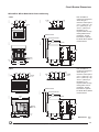
Charging handle
Manual opening push button
Manual closing push button
Stored energy mechanism status indicator
(charged or discharged)
Main contact position indicator (open or
closed)
Disconnected position locking (key
interlock)
Disconnected position padlocking
Drawout position indicator showing that the
circuit breaker is in the connected, test or
disconnected position
Racking crank storage
Door escutcheon
Fault indicator and reset button
Open position locking (key interlock)
d
disconnecte
10
9
8
7
6
©1995 Square D—All Rights Reserved
11/98
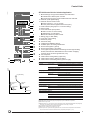
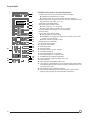
Control Units
06313014
The circuit breaker can be equipped with a microprocessor-based, electronic control unit which
provides all the traditional protection of the universal power circuit breaker (long-time, short-time,
instantaneous and ground-fault) plus other built-in functions:
n RMS sensing (standard)
n Alarm switch (standard)
n Overcurrent trip switch (standard)
n Interchangeable rating plugs (on STR28DP, STR38SP and STR58UP)
n Thermal memory and I2t ramp (standard on STR 38-58 control unit)
n Defeatable instantaneous (standard on STR 38-58 control unit)
n Zone-selective interlocking for ground-fault and short-time (option)
n Current and load meter (option)
n Load-monitoring outputs (option)
n Fault indicators (option)
n Communication ability (option)
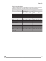
Control Units
STR 18M
STR 28D
STR 38S
STR 58U
Basic Features
Long-time (1)
Short-time
Setting
Adjustable
Adjustable
Adjustable
Delay
Fixed
Fixed
Adjustable
Pickup
Adjustable
Adjustable
Delay
Adjustable
Adjustable
Adjustable
Fixed (2)
Adjustable (2)
Standard
Standard
Standard
n
n
Instantaneous
Adjustable
Test Receptacle
Additional Features (Options)
Ground-fault Protection (3)
Built-in Ammeter
n
Fault Indicators
n
n
n
n
Segregated Alarm Switch
n
Zone-selective Interlocking
n
Load Monitoring
n
Communication Outputs
n
(1) Long-time pickup at 1.1 current setting.
(2) Defeatable on N1 and H1 types.
(3) Two types: residual sensing (T) or residual source ground return (W).
7
11/98
©1995 Square D—All Rights Reserved
06313015
Control Units
STR 28D Control Unit for General Application
1
push to reset
1. Mechanical pop-out type fault indicator and reset button:
n Indicates that a fault trip has occurred
n Prevents closing of the circuit breaker after fault until reset
2. Ammeter (LCD digital display)
3. Ammeter selector used to read:
n Phase currents (1, 2, 3, N)
n Or the phase with the highest load current (max.)
4. Load indication (bar graph in % of current setting)
5. Sensor rating
6. Rating plug (on STR 28DP)
7. Long-time current setting
8. Instantaneous pickup
9. Local and remote pre-trip alarm:
n LED on at 90% of current setting
n LED flashing on overload (1)
n Remote indication by static contact
10. Available spaces for setting identification
11. Test receptacle
2
I1
I2
I
I3
90%
STR 28 D
50%
3
4
5
20%
Ir
90
.9
.92
.95
.88
%Ir
.98
.85
105
6
7
1
.8
xIo
Im
4
5
3
6
2
1.5
8
xIr
t
8
10
Ir :
Ir
9
10
Overcurrent Protection—RMS Sensing
Im :
Long-time
Current Setting
i
+
Rating Plug
–
11
test
06313016
STR 28DP: 0.8 to 1 x Rating Plug (Pickup at 1.1 x Setting)
STR 28D: 0.4 to 1 x Current Sensor (Pickup at 1.1 x Setting)
Im
t
Long-time Setting
Instantaneous
Max. Delay
Fixed: 7.5 sec. at 6 x Current Setting
Current Sensor
Plug Rating
250 A
250–200–150–125 A
400 A
400–300–250–200 A
600 A
600–500–400–300 A
800 A
800–600–500–400 A
1200 A
1200–1000–800–600 A
1600 A
1600–1200–1000–800 A
2000 A
2000–1600–1200–1000 A
2500 A
2500–2000–1600–1200 A
3000 A
3000–2500–2000–1600 A
3200 A
3200–3000–2500–2000–1600 A
4000 A
4000–3200–3000–2500–2000 A
5000 A
5000–4000–3200–3000–2500 A
6300 A
6300–6000–5000–4000–3200–3000 A
Pickup
1.5 to 10 x Current Setting
Built-in Ammeter (Optional)
Option I
Instantaneous
Values Displayed
Phase 1, 2, 3, Max., Neutral Current
Accuracy
±1.5 % (2)
Bar Graph Indication
Phase 1, 2, 3—10% Steps
Control Power
Not Required (3)
Fault or Alarm Indicators
Not Discriminated
I
Local
Pop-out Type Indicator and LED Pre-trip Alarm
Remote
Overcurrent Trip and Pre-trip Alarm Switches
(see pp. 14–15)
(1) According to time-current curves: between 105% and 120% of current setting.
(2) Total accuracy including current sensors: ±4.5%.
(3) Control power not required for loads greater than 20% of current sensor. Required for load less than 20%
of current sensors if maximum demand memory requested (see diagram on p. 43).
Note: Io: Rating plug
In: Sensor rating
Ir: Long-time pickup
tr: Long-time delay
Im: Short-time pickup
tm: Short-time delay
I: Instantaneous pickup
Ih: Ground-fault pickup
th: Ground-fault delay
8
©1995 Square D—All Rights Reserved
11/98
Control Units
06313017
STR 38S Control Unit for Selective Application
1
push to reset
2
I1
I2
3
4
I
I3
90%
STR 38 S
5
50%
6
7
8
9
20%
Ir
90
.9
.92
.95
.88
%Ir
.98
.85
105
1
.8
xIo
Im
4
tm
.4
5
3
6 .3
2
1.5
8
10
xIr
t
.3
10
.2
.2
.1
.1
0
on I2t off
11
12
13
I
Ir :
Ir fault
Im :
max.
tr
off
xIn
th :
Ih
Ih
500
fault
Im fault
tm
th
600
800
400
320
I
250
A
th
.3
.4
T
.4
14
.3
1000 .2
.2
.1
.1
1200
on I2t off
15
16
i
overcurrent
+
–
–
+
test
ground
18
F
test
17
19
1. Mechanical pop-out type fault indicator and reset button:
n Indicates that a fault trip has occurred
n Prevents closure of the circuit breaker after fault until reset
2. Ammeter (LCD digital display)
3. Ammeter selector used to read:
n Phase currents (1, 2, 3, N, ground)
n Or the phase with the highest load current (max.)
4. Load indication (bar graph in % of current setting)
5. Sensor rating
6. Local and remote pre-trip alarm:
n LED on at 90% of current setting
n LED flashing on overload (1)
n Remote indication by static contact
7. Rating plug (on STR 38SP)
8. Long-time current setting
9. Short-time pickup
10. Short-time delay
11. Instantaneous ON/OFF selector
12. Available space for setting identification
13. Ground-fault (option T) pickup
14. Ground-fault (option T) time delay
15. Local (option F) fault indicators consisting of built-in light emitting
diodes; fault indicators differentiate the three causes of tripping:
overload, short circuit and ground fault, if any
16. Test receptacle
17. Fault indicator saving battery (option PIL)
18. Fault indicator reset or battery test button
19. Fault indicator reactivating button (option PIL) (2)
Overcurrent Protection—RMS sensing
Long-time
Current Setting
STR 38SP: 0.8 to 1 x Rating Plug (Pickup at 1.1 x Setting)
Delay
Fixed: 7.5 sec. at 6 x Current Setting
06313018
STR 38S: 0.4 to 1 x Current Sensor (Pickup at 1.1 x Setting)
t
Thermal Memory as Standard
Rating Plug
4 to 6 Rating Plugs Available Per Sensor Rating: See STR 28D Control Unit, p. 8
Short-time
Pickup
Delay Bands
Long-time Setting
1.5 to 10 x Current Setting
0–0.1–0.2–0.3–0.4 with I2t OFF
0.1–0.2–0.3 with I2t ON
Instantaneous
Pickup
High-set Fixed Type (3)—Defeatable on N1 and H1 Types
Ground-fault Protection (Option T or W) (4)
Ground-fault
Pickup
Ground-fault
Delay
Short-time
Pickup
Pickup
0.1 x Current Sensor to 1200 A (5)
Delay Band
0.1–0.2–0.3–0.4 with I 2t Ramp ON/OFF Switch
Fault Indicators (Option F)
Not Discriminated
Short-time Delay
Discriminated
Instantaneous
I
Local
Mechanical Pop-out Type Indicator and LED Pre-trip Alarm
Remote
Overcurrent Trip and Pre-trip Alarm Switches (see pp. 14–15)
Local
With Option F (see p. 14)
Built-in Ammeter (Option I)
Values Display
Phase 1, 2, 3, Max., Neutral and Ground Current
Accuracy
±1.5% (6)
Bar Graph Indication Phases 1, 2, 3—10% steps
Control Power
Not Required (7)
(1) According to time current curves: 105% to 120% of current setting.
(2) With PIL option, fault indicator lights (15) will light up only when this button is pushed in.
(3) See values on pp. 38–40.
(4) Residual scheme (T). The maximum ground-fault pickup meets 1999 National Electrical Code paragraph
230-95 (a) (not exceeding 1200 A). Source Ground Return scheme (W) on request.
(5) 0.1 minimum pickup requires 24 Vdc external power.
(6) Total accuracy including current sensors: ±4.5%.
(7) Control power not required for loads greater than 20% of current sensor. Required for loads less than
20% of current sensor if maximum demand memory requested (see diagram, p. 43).
9
11/98
©1995 Square D—All Rights Reserved
06313019
Control Units
V
push to reset
reset V
I+T
L+I
L
off
L+I+T
I
1
2
T
L+T
3
I1
I2
4
I
I3
5
90%
STR 58 U
6
7
8
9
10
11
50%
20%
Ir
90
tr
.88
120
.92
.95 60
.85
.9
.98 30
240
%Ir
105
1
.8
Im
norm
min.
τ tr
tm
.4
5
3
6 .3
2
1.5
8
Ir :
12
.2
.1
.1
0
on I2t off
10
12
.3
.2
xIr
I
t
4
480
15
at 1.5Ir
xIo
13
14
15
14
8
19
Ir fault
Im :
4
22
Max.
2
tr
21
xIn
Ih 1200A Max th
th :
Ih
fault
Im fault
tm
th
I
i
overcurrent
+
–
–
+
test
22
23
F
test
T
.4
600
800
320
250
1000 .2
.2
.1
.1
1200
on I2t off
A
Ic1
.93
.95
.7
.8
.98
.6
1
xIr
16
17
.3
.3
Ic2
.9
.86
.85
ground
.4
500
400
.85
.9
.8
R
.95
.5
1
xIr
18
19
20
STR 58U Control Unit for Universal Application
1. Mechanical pop-out type fault indicator and reset button:
n Indicates that a fault trip has occurred
n Prevents closure of the circuit breaker after fault until reset
2. Switch selector for the type of fault to be remotely indicated and reset
flat push button (see option FV, p. 15)
3. Ammeter (LCD digital display)
4. Ammeter selector used to read:
n Phase currents (1, 2, 3, N, ground)
n Or the phase with the highest load current (max.)
5. Load indication (bar graph in % of current setting)
6. Sensor rating
7. Local and remote pre-trip alarm:
n LED on at 90% of current setting
n LED flashing on overload (according to time current curves: 105%
to 120% of current setting)
n Remote indication by static contact
8. Rating plug (on STR 58UP)
9. Long-time current setting
10. Long-time delay setting
11. Short-time pickup
12. Short-time delay
13. Thermal memory min./max. selector
14. Instantaneous pickup
15. Ground-fault (option T or W) pickup
16. Ground-fault (option T or W) time delay
17. Available space for setting identification
18. Load monitoring (option R) pickups (see p. 16)
19. Test receptacle
20. Fault indicator saving battery (option PIL)
21. Local (option F) fault indicators consist of built-in light emitting diodes
which differentiate the three causes of tripping: overload, short circuit
and ground fault, if any
22. Fault indicator reset or battery test button
23. Fault indicator reactivating button (with PIL option, fault-indicator
lights (21) will only light up when this button is pushed in)
10
©1995 Square D—All Rights Reserved
11/98
06313020
Control Units
t
Overcurrent Protection—RMS Sensing
Long-time
Current Setting
STR 58UP: 0.8 to 1 x Rating Plug (Pickup at 1.1 x Setting)
STR 58: 0.4 to 1 x Current Sensor (Pickup at 1.1 x Setting)
Delay Bands
Long-time Pickup
0.94–1.88–3.75–7.50–15–30s at 6 x Current Setting
Thermal Memory as Standard with Min./Max. Selector
Rating Plug
Long-time Delay
Ground-fault
Pickup
Ground-fault
Delay
Short-time Pickup
Short-time Pickup
Instantaneous Pickup
I
Short-time
Current Sensor
Plug Rating
250 A
250–200–150–125 A
400 A
400–300–250–200 A
600 A
600–500–400–300 A
800 A
800–600–500–400 A
1200 A
1200–1000–800–600 A
1600 A
1600–1200–1000–800 A
2000 A
2000–1600–1200–1000 A
2500 A
2500–2000–1600–1200 A
3000 A
3000–2500–2000–1600 A
3200 A
3200–3000–2500–2000–1600 A
4000 A
4000–3200–3000–2500–2000 A
5000 A
5000–4000–3200–3000–2500 A
6300 A
6300–6000–5000–4000–3200–3000 A
Pickup
1.5 to 10 x Current Setting
Delay bands
0–0.1–0.2–0.3–0.4 with I2t OFF
0.1–0.2–0.3 with I2t ON
Zone-selective Interlocking with Option Z (see p. 13)
Instantaneous
Pickup
Adjustable from 2 to Max. Value (1); Defeatable on N1 and
H1 Types
Ground-fault Protection (Option T or W) (2)
Pickup Delay Band
0.1 x Current Sensor to 1200 A (3)
0.1–0.2–0.3–0.4 with I2t Ramp ON/OFF Switch
Zone-selective Interlocking with Option Z (see p. 13)
Fault Indicators (Option F)
Not Discriminated
Discriminated
Local
Mechanical Pop-out Type Indicator and LED Pre-trip Alarm
Remote
Overcurrent Trip and Pre-trip Alarm Switches (see pp. 14–15)
Local
With Option F (see p. 14)
Remote
With Option FV (see p. 15)
Built-in Ammeter (Option I)
Values Display
Phase 1, 2, 3, Max., Neutral and Ground Current
Accuracy
±1.5% (4)
Bar Graph Indication Phase 1, 2, 3—10% Steps
Control Power
Not Required (5)
Load Monitoring (Option R)
Inverse Time Alarm
Pickups
Ic1 = 0.8 to 1 x Current Setting
Ic2 = 0.5 to 1 x Current Setting
Time delay
See Curve, p. 41
Outputs for Communication through DIGIPACT® System (Option C)
Transmitted Values
Entire Settings of the Trip Unit
Circuit Breaker Status: Open, Tripped, Closed
Alarms: Overload, Type of Fault, Internal Watchdog (6)
Ammeter Values: Phase, Neutral, Ground, Max. Currents
(1) See values on pp. 38–40.
(2) Residual scheme (T). The maximum ground-fault pickup meets 1999 National Electrical Code paragraph
230-95 (a) (not exceeding 1200 A). Source Ground Return scheme (W) on request.
(3) 0.2 minimum pickup only with external power.
(4) Total accuracy including current sensors: ± 4.5%.
(5) Control power not required for loads greater than 20% of current sensors. Required for loads less than
20% of current sensor if maximum demand memory requested (see diagram, p. 43).
(6) Internal watchdog: Control unit internal temperature.
11
11/98
©1995 Square D—All Rights Reserved
06313182
Control Units
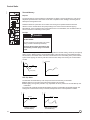
Thermal Memory
push to reset
Purpose
The thermal memory function allows an optimization of cables or bus bar protection in case of low
amplitude repetitive faults. Such faults can be due to repetitive motor startings, fluctuating load or
subsequent closing after a fault.
I1 I2 I3
90%
STR 58 U
50%
Traditional electronic protection has no effect when facing such repetitive faults because the
duration of each overload above the pickup setting is too short to achieve effective tripping.
Nevertheless, each overload involves a temperature rise in the installation, the cumulative effect of
which could lead to overheating of the system.
20%
Ir
xIn
tr
xIo
Im
at 1.5Ir
tm
xIo
t
Principle
I
xIn
Ih
i Ic1
th
T
Ic2
R
DANGER
xIn
HAZARD OF ELECTRICAL SHOCK, BURN
OR EXPLOSION.
test
xIr
xIr
F
test
Use "min" position for emergency only when
closing on fault is absolutely necessary.
Failure to observe these precautions will
cause death, personal injury or electrical
shock.
06313184
06313183
The thermal memory function remembers and integrates the thermal heating caused by each pickup
setting overrun. Before tripping, the integrated heating value will reduce the associated time delay
and, therefore, the reaction of the control unit will be closer to the real heating of the power network
system. After tripping, the memory will also reduce the time delay when closing the circuit breaker
on fault.
I
Temperature
Pickup Setting
t
t
STR Trip Units
06313185
06313186
The STR 38S and STR 58U trip units incorporate the thermal memory as standard:
n Before tripping on long-time and ground-fault protection (if provided)
n After tripping on long-time protection only, adjustable min./max. position for the STR 58U trip unit
is standard
The control unit measures the internal temperature rise of the circuit breaker by thermal resistors. The
cooling time constant of the memory is not fixed, but depends on the over-temperature condition.
I2 t
I 2t
Trip Level
Trip Level
t
STR Trip Unit with
Thermal Memory
t
STR Trip Unit without
Thermal Memory
12
©1995 Square D—All Rights Reserved
11/98
06313021
Control Units
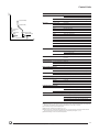
Neutral Sensor
Main Circuit Breaker
T1
T2
S1
S2
06313023
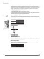
Ground-fault protection may be applied on
3Ø4W or 3Ø3W circuits. On 3Ø4W circuits an
external neutral sensor must be used. This
neutral current sensor must have the same
ampere rating as the circuit breaker sensor.
Neutral
Ground-fault
Neutral CTs
S1
T1
S2
T2
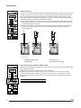
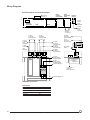
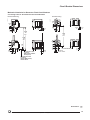
Zone-selective Interlocking (ZSI)
Option Z on the STR58U control unit provides
selective interlocking on short time or ground
fault. A pilot wire links several trip units in the
distribution network, as shown in the opposite
figure. In the event of a fault, the trip unit will
respond to the preset delay only if receiving a
signal from the downstream unit. If not receiving
a signal, the tripping will be instantaneous.
Therefore, the fault is cleared instantaneously
by the nearest circuit breaker: the thermal
stresses (I2t) in the network are minimized,
without any effect on the correct time-delay
coordination in the installation.
Note: #18 to #14 AWG cables, max. length 90 ft./30m.
06313022
A
Z12
Z11
Z22 Out
Z21 In
1
Fault 1
Circuit breaker A will clear the fault
instantaneously, regardless of its time-delay
setting.
B
Z12
Z11 Out
Z22
Z21 In
Z12
Z11 Out
Z22
Z21 In
2
Z12
Z11
Z22
Z21
Out
In
Z12
Z11
Z22
Z21
Out
In
Z12
Z11 Out
Z22
Z21 In
Fault 2
Circuit breaker B will inform upstream circuit
breaker A that it is clearing the fault and will
prevent it from tripping instantaneously. Circuit
breaker A will trip at the end of its time delay
setting if the fault is not cleared during this time.
Note:
n Drawout circuit breaker terminals are
delivered with "in" terminals jumpered.
Remove the jumper when interlocking with a
downstream circuit breaker.
n The MASTERPACT circuit breaker may also
be interlocked with COMPACT® NS and CK
type molded case circuit breakers with ZSI
option.
n Do not ground ZSI wiring.
Cable Size
#18–#14 AWG/1.5mm2
Max. Length
90 ft./30 m
Wiring
Twisted in Pairs One Turn per 4 in./10 cm
No. of Circuit Breakers
Upstream: 2
Downstream: No Limit
13
11/98
©1995 Square D—All Rights Reserved
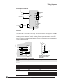
Fault Indicator (F)
push to reset
I1 I2 I3
90%
STR 58 U
50%
20%
Ir
tr
xIo
Im
at 1.5Ir
tm
xIo
t
I
i Ic1
06313025
xIn
Ih
T
th
xIn
Ic2
24 Vdc
1W
06313027
In addition to the mechanical fault indicator, this indicator differentiates the three causes of tripping:
overload, short circuit or ground fault, if any. Three light-emitting diodes indicate separately longtime, short-time/ instantaneous and ground-fault trip. A flat push button allows resetting of the
indicator after tripping. A separate power supply is required to maintain the indication after tripping
of the circuit breaker. Two different possibilities are offered:
n Connecting a reliable 24 Vdc control voltage on F1-F2. Auxiliary power module (AD) is used for
other voltages. When the control source is considered as unreliable, a battery pack (BAT) is to
be added to an AD power module.
n From a built-in battery module. When no external control source is available, a built-in battery
module may be ordered (option PIL). This module integrates battery testing and indicator
reactivating buttons.
06313026
06313024
Control Units
+
R
AD (1)
test
xIr
xIr
AD (1)
F
test
+
BAT
+
F1
F2
F1
F2
F1
F2
(1) AC: 120 V, 60 Hz
DC: 24–48–125 Vdc
Configuration with Reliable
Control Voltage
Configuration with
Interruptible Control Voltage
06313028
Alarm Indicator Pre-trip Alarm Switch (ALR)
push to reset
Delivered as standard with control unit. The alarm indicator is a fixed, front face light-emitting diode
which operates as follows:
n Fixed when the current exceeds 90% of the current setting.
n Flashing on overload: according to time-current curves, 105% to 120% of current setting.
The pre-trip alarm switch is a static contact which closes when in the overload zone, up to the
tripping of the circuit breaker. This contact can be used for ultimate load shedding, alarm before
tripping, etc.
I1 I2 I3
90%
STR 58 U
50%
ALR
20%
Ir
tr
xIo
Im
at 1.5Ir
tm
Output Characteristics
0.1 A/240 Vac (Optical Triac)
Power Supply
Not Required
xIo
t
I
xIn
Ih
i Ic1
th
T
Ic2
R
xIn
test
xIr
xIr
F
test
14
©1995 Square D—All Rights Reserved
11/98
Control Units
Overcurrent Trip Switch (SDE)
06313029
Delivered standard with control unit. In addition to the fault trip indicator/reset button, one SPDT
switch provides alarm/lockout information. This SPDT switch is operated only when the circuit
breaker is tripped by the control unit. When the circuit breaker is reset, the "a" switch (alarm) is
open and the "b" switch (lockout) is closed.
Output Characteristics
SPDT 10 A/240 Vac
Power Supply
Not Required
Fault
82
84
SDE
81
V
06313030
Segregated Trip Switch (FV)
push to reset
This switch works exactly as the standard overcurrent trip switch (SDE) except that a commutator
on the front face is used to choose the type of fault which will operate the contact: overload, shortcircuit, ground-fault, or any combination of these types. This option can be used in addition to the
SDE switch for remote signalization of particular types of faults. A flat push button allows resetting of
the indicator after tripping.
I1 I2 I3
90%
STR 58 U
50%
Output Characteristics
5 A/240 Vac
Power Supply
Required
20%
tr
xIo
Im
at 1.5Ir
tm
Wired in parallel with the remote opening button which operates the shunt trip, the option FV
contact provides an electrical interlock which prevents the circuit breaker from being closed after the
pre-selected type of faults: for example the circuit breaker will be able to be remotely closed after
overload, but not after short circuit.
xIo
t
I
i Ic1
th
T
Ic2
R
xIn
test
xIr
xIr
06313031
xIn
Ih
06313032
Ir
Fault
Remote
Open
Fault
F
test
V2
C2
V2
MX
V
V
V1
V1
C1
15
11/98
©1995 Square D—All Rights Reserved
06313033
Control Units
Load monitoring (R)
push to reset
Option R provides two independent static contacts which operate when the current exceeds
adjustable pickup limits:
n When the current exceeds the limit Ic1 (or Ic2), the contact C-R1 (or C-R2) closes following an
inverse time characteristic A.
n When the current drops below the limit Ic1 (or Ic2), the contact C-R1 (or C-R2) opens with
constant time delay (10 seconds) B.
These contacts can be used for load shedding, alarms, indications, etc.
I1 I2 I3
90%
STR 58 U
50%
20%
Ir
tr
xIo
Im
at 1.5Ir
tm
Voltage
240 Vac max.
Outputs
0.1 A triac
xIo
t
xIn
Ih
i Ic1
th
T
Ic2
R
06313034
I
t
xIn
Long-time
test
xIr
xIr
F
test
B
A
I
Test Kits
06313036
06313035
Every control unit is equipped with a test receptacle that can be used with a test kit. Tests
performed by test kits are only functional tests designed to electrically test the operating integrity of
the control unit, the flux transfer device and the mechanical operation of the circuit breaker. Tests
are not designed to calibrate the circuit breaker. Calibration can only be done at the factory.
Mini Test Kit
Calibration Test Kit
16
©1995 Square D—All Rights Reserved
11/98
Control Units
Communication
MASTERPACT circuit breakers can be easily connected to a supervising personal computer using
the DIGIPACT® system. The following four functions can thus be provided:
n Indication:
o Status of the circuit breaker (on, off or tripped; connected or disconnected)
o Causes of tripping (overload, short circuit or ground fault)
n Monitoring:
o Operation of circuit breaker (open, closed or reset)
o Resetting a molded case circuit breaker (COMPACT NS and CK)
n Management:
o Control unit settings
o Pre-trip alarm
o Load monitoring status
o Control unit internal temperature alarm
o Number of operation cycles performed by the circuit breaker
n Metering:
o RMS value of the current in three phases
06313037
Communication with Supervision,
Personal Computer
MODBUS ®/JBUS
IN
LIN GER
MERSV
pulsar
JBus
BBus
com
24V
OK
error
1 3
com
error
DIGIPACT DC150
Data Concentrator
POWERLOGIC ®
Circuit Monitor
POWERLOGIC
Power Meter
N∞1
N∞1
Internal Bus
SC150 Indication and
Control Interface
SC150 Indication and
Control Interface
push
to
trip
push
push
COMPACT NS Circuit Breaker
with Communications-type
Auxiliary Switches, Motor
Operator and Carriage Switches
GERIN
MERLIN
9
multi
ATB1s
MASTERPACT Circuit Breaker
with STR 58U Trip Unit and
Communications Option
MASTERPACT Circuit Breaker
with STR 58U Trip Unit and
Communications Option
ATB MULTI 9 ® Interface
for C60 with Motor Operator
17
11/98
©1995 Square D—All Rights Reserved
Control Units
06313038
SC150 Indication and Control Interface
Function
The SC150 indication and control interface is used to:
n Transmit to the DC150 data concentrator:
o Status information (on, off, tripped, tripped due to electrical fault, tripped due to ground fault)
for COMPACT CK and MASTERPACT circuit breakers or any other power circuit actuator
o The connected or disconnected status of withdrawable COMPACT CK and MASTERPACT circuit
breakers
o The status of any external contact
n Receive commands transmitted by a personal computer or programmable logic controller (PLC)
via the DC150 data concentrator (on, off and reset of the COMPACT CK and MASTERPACT
circuit breakers or any other power circuit actuator)
n Receive the information transmitted by the communications option on electronic control units
(STR43, STR53, STR55 and STR58) installed in COMPACT NS, COMPACT CK and
MASTERPACT circuit breakers:
o Trip-unit settings
o The RMS value of the current in the three phases and the neutral
o Current overloads
o The causes of tripping (overloads, short circuits or ground fault)
n Count the number of cycles carried out by the device
The SC150 interface is connected to:
n The DC150 data connector
n The auxiliary switches (OF, SD, SDE, SDV, CE, CD) on the circuit breaker with which the interface
is associated
n The motor operator for execution of the on, off and reset commands
n The communications outputs of the STR43, STR53, STR55 and STR58 control units installed in
COMPACT NS, COMPACT CK and MASTERPACT circuit breakers
A non-assigned digital input is available for other use. The SC150 interface is associated with a
single circuit breaker.
Important: The SC150 interface is used with COMPACT NS circuit breakers to:
n Remote to the user the information supplied by the communications option on STR43 and STR53
control units
n Actuate non-communicating motor operators
n Count the number of cycles carried out by the circuit breaker
Note: When associated with the SC150 interface, COMPACT NS circuit breakers are equipped with
standard auxiliary switches and motor operators. The SC150 indication and control interface is not
required with COMPACT NS circuit breakers equipped with communication-type auxiliary switches
or a communication-type motor operator.
Information or Function Managed by the SC150 Indication and Control Interface
Information Transmitted or
Function Carried Out
Devices Associated with the SC150 Interface
Display Device Status:
n On, Off
n Tripped
n Tripped Due to Electrical Fault
n Tripped Due to Ground Fault
n Connected or Disconnected Position
Circuit Breaker or Other Power-circuit Actuator
+ Standard OF Auxiliary Switches
+ Standard SD Auxiliary Switches (COMPACT Circuit Breakers)
+ Standard SDE Auxiliary Switches
+ SDV Auxiliary Switches (COMPACT NS) or Output Contact of a Ground-fault Relay
+ Standard CE and CD Auxiliary Switches
Remotely Control a Device (On, Off or Reset)
COMPACT or MASTERPACT Circuit Breaker Equipped with Standard Motor Operator
Count the Number of Operating Cycles
As Above
Display the Cause of Tripping and the
Trip Unit Settings (Settings and Time Delays)
COMPACT or MASTERPACT Circuit Breaker Equipped with STR43, STR53, STR55
or STR58 Electronic Trip Unit with Communications Option (COM)
Trip an Alarm for Long-time Fault
As Above
Display the Value of the Current for Each Phase
As Above
Display Internal Temperature of Switchboard
PT100 Probe –4 to 212°F (–20 to 100°C)
18
©1995 Square D—All Rights Reserved
11/98
Control Units
SC150 Indication and Control Interface (continued)
Technical Data
Digital Inputs (24 V, Self-powered by the SC150 Interface)
O Auxiliary Switch
One Input
F Auxiliary Switch
One Input
SD Auxiliary Switch (Tripping)
One Input
SDE Auxiliary Switch (Tripping Due to Electrical Fault)
One Input
CE Auxiliary Switch
One Input
CD Auxiliary Switch
One Input
SDV Auxiliary Switch (Tripping Due to Ground Fault)
One Input
Other Uses
One Unassigned Input
Electrical Characteristics
Voltage (Supplied by SC150)
24 Vdc
Current (Supplied by SC150)
120 mA dc
Resistance in On-state
< 30 mΩ
Resistance in Off-state
> 10000 MΩ
Control Outputs
Opening
One N.O. and N.C. Control Terminal
Closing
One N.O. Control Terminal
Reset
One N.O. Control Terminal
Note: The opening, closing and reset control signals delivered by
the SC150 interface are of the impulse type. The pulse
duration is one second for the closing signal and two
seconds for the opening and reset signals.
Voltage
100–440 Vac/24–250 Vdc
Interrupting Rating
AC
2500 VA
DC
300 W Continuous/500 W for Two Seconds
Utilization Category
AC15/DC13 as Defined by IEC 947-5
Operating Temperature Range
–13 to 158°F (–25 to 70°C)
Storage Temperature Range
–67 to 185°F (–55°C to 85°C)
Damp Heat Not in Operation (IEC 68-2-30)
6 cycles 77°F (25°C)/131°F (55°C)/RH 95%
Damp Heat in Operation (IEC 68-2-56)
2 days 86°F (30°C)/RH 93%
Salt Mist (IEC 68-2-52)
Kb Test, Severity Level 2
Electromagnetic Compatibility
Electrostatic Discharges
(IEC 1000-4-2)
Level 3
Radiated Susceptibility
(IEC 1000-4-3)
Level 3
Low-energy Conducted
Susceptibility (IEC 1000-4-4)
Level 4
High-energy Conducted
Susceptibility (IEC 1000-4-5)
Level 4
Conducted and Radiated
Emissions (EN 50081-1)
Class A
Dimensions
2 x 4 x 6.5 in. (50 x 105 x 165 mm)
Weight
2.5 lb. (1 kg)
Degree of Protection (as Per IEC 529)
Vibrations (Lloyd’s 1996)
Front Face
IP30
Other Faces
IP30
Connections
IP20
Fc Test
5–13.2 Hz: .04 in. (1 mm)
13.2–100 Hz: .03 oz. (0.7 g)
Wiring Diagram
See p. 44
Dimensions
See pp. 61
19
11/98
©1995 Square D—All Rights Reserved
Control Units
06313039
DC150 Data Concentrator
Function
The DC150 data concentrator is used to:
n Centralize all the information supplied by the various communicating devices:
o Auxiliary switches and motor operator
o SC150 indication and control interface
n Make information available to a personal computer or programmable logic controller (PLC) via the
MODBUS/JBUS protocol
n Log status changes and tripping of the communicating circuit breakers in order to provide the
user with a list of time-stamped events
n Supply the 24 V and 15 V power required by the communicating devices and the internal bus
n Carry out addressing for the communicating devices
Each DC150 data concentrator can be connected to a maximum of 48 instrumented outgoing or
incoming circuits.
Information or Function Managed by the DC150 Data Concentrator
Information Transmitted or
Function Carried Out
Devices Required to Display the Information or
Carry Out the Function
Display Device Status:
Circuit Breaker or Other Power-circuit Actuator
n
o
On, Off, Tripped, Tripped Due to Electrical Fault,
Connected, Disconnected
o
o
o
n
Tripped Due to Ground Fault
o
COMPACT NS Circuit Breaker + Communicating Auxiliary Switches
COMPACT/MASTERPACT Circuit Breaker + SC150 Indication and Control
Interface
COMPACT NS Circuit Breaker + Communicating Auxiliary Switches
MULTI 9 Control Device + ATB Interface
COMPACT NS Circuit Breaker + Vigi or Ground-fault Relay + SC150
Indication and Control Interface
Remotely Operate a Circuit Breaker
(On, Off or Reset)
n
Inhibit Reset Following Tripping Due
to Electrical Fault
As Above
Select Operating Mode of Motor
Operators (Local or Remote)
As Above + CLS150 Indication and Local Control Module
Measure Currents (Phases and Neutral)
COMPACT/MASTERPACT Circuit Breaker Equipped with Electronic Control Unit
Comprising Communications Option + SC150 Indication and Control Interface
Count Number of Operating Cycles
SC150 Indication and Control Interface
Display Causes of Tripping
COMPACT/MASTERPACT Circuit Breaker Equipped with Electronic Control Unit
Comprising Communications Option + SC150 Indication and Control Interface
Display Trip Alarm for Long-time Fault
As Above
Display Trip Unit Settings
(Thresholds and Time Delay)
As Above
COMPACT NS Circuit Breaker + Communicating Motor Operator
COMPACT/MASTERPACT Circuit Breaker + SC150 Indication and Control
Interface
n MULTI 9 Control Device + ATB Interface
n
Accessories
Connection
Junction Block for Internal Bus
Cat. No. 50778
RS485/RS232 Conversion Unit
Cat. No. 50786
Junction Block
06313042
06313116
06313040
RS232/RS485 Converter
Cat. No. 50779 65 ft. (20 m)
or 50780 330 ft. (100 m)
An RS232/RS485 converter is required for connection to a personal computer
equipped with an RS232 output to the MODBUS/RS485 bus.
06313041
Connection to Personal Computer
Cable for Internal Bus
Connector
Internal Bus Cable
20
©1995 Square D—All Rights Reserved
11/98
Control Units
DC150 Data Concentrator (continued)
1
06313043
2
3
4
6
Description
5
1.
2.
3.
4.
MERLIN GERIN
Digipact
DC150
BBus
JBus
OK
com
com
error
24V
error
7
5.
9600
19200
0
F
1
456
23
F
0
78 9
CD E
N°2
AB
N°1
CD E
15
78 9
AB
456
23
16
N°1
N°2
8
9
1
14
10
13
12
11
6.
7.
8-9.
10.
11.
12.
13.
14-15.
16.
LED indicating that address is correct
LED indicating that address is incorrect
LED indicating presence of 24 V power
LED indicating communication on
internal bus
LED indicating MODBUS/JBUS
communication
LED indicating MODBUS/JBUS error
MODBUS/JBUS speed setting
Coding wheels for JBUS address
JBUS connector
Power supply connector
Internal bus connector
Confirmation button
Keys for DIGIPACT module addresses
Address display
Technical Data
Electrical Characteristics
Voltage
110–240 Vac/115–125 Vdc
Tolerance
+10%–15%
Operating Temperature Range
–13 to 158°F (–25 to 70°C)
Storage Temperature Range
–67 to 158°F (–55 to + 70°C)
Electromagnetic Compatibility
Electrostatic Discharges
Level 3
(IEC 1000-4-2)
Radiated Susceptibility
Level 3
(IEC 1000-4-3)
Low-energy Conducted
Level 4
Susceptibility (IEC 1000-4-4)
High-energy Conducted
Level 4
Susceptibility (IEC 1000-4-5)
Conducted and Radiated
Class A
Emissions (EN 50081-1)
Protocol
MODBUS/JBUS (Slave)
Speed
9600 or 19200 Baud
Data Format
Eight Bits, No Parity, One Stop
Physical Link
RS485 (2-Wire or 4-Wire)
Implemented MODBUS/JBUS Protocol Functions
Read N Consecutive Bits
Function 1 or 2
Read N Words
Function 3 or 4
Write One Bit
Function 5
Write One Word
Function 6
Write N Bits
Function 15
Write N Words
Function 16
Weight
4 lb. (1.5 kg)
Degree of Protection (as Per IEC 529)
IP30
IP20 (Connections)
Wiring Diagrams
See p. 45
Dimensions
See p. 61
21
11/98
©1995 Square D—All Rights Reserved
Control Units
Sizing of the DIGIPACT Internal Bus
Sizing of the DIGIPACT internal bus depends on two factors:
n The number of devices on the bus
n The length of the bus
Number of Devices
As on any communications network, the number of devices that may be connected on the
DIGIPACT internal bus is limited. The maximum number of devices is calculated in terms of
"communication points." Each type of device represents a number of points indicated in the table
below. The total number of points for the various devices connected to a single bus must not exceed
100. If the required devices represent more than 100 points, simply add a second DIGIPACT
internal bus with a second DC150 data concentrator. The same sizing rules apply to the second bus
as well.
Communicating Device
Number of Points
DC150 Data Concentrator
4
Communicating Auxiliary Switches OF, SD, SDE for COMPACT® NS Circuit Breakers
2
Communicating Motor Operator and Auxiliary Switches for COMPACT NS Circuit Breakers
2
Communicating Auxiliary Switches CE and CD for COMPACT NS Circuit Breakers
0
SC150 Indication and Control Interface
4
CLS150 Indication and Local Control Module Associated with:
n Communicating Auxiliary Switches
n Communicating Motor Operator and Auxiliary Switches
n SC150 Indication and Control Interface
0
0
0
PM150 Power Meter
4
ATB MULTI 9 Interface
2
Length of Bus
The table below indicates the cross-sectional area of the cable that must be used depending on the
total length of the bus.
Cross-sectional Area
Maximum Length of Bus
0.03 in.2 (0.75 mm2)
660 ft. (200 m)
0.06 in.2 (1.5 mm2)
1310 ft. (400 m)
0.1 in.2 (2.5 mm2)
2300 ft. (700 m)
The total resistance of the two wires for the bus must be less than 12 ohms. If the bus is too long,
simply:
n Increase the cross-sectional area of the cable.
n Create two shorter buses for the installation (in this case, a second DC150 data concentrator
is required).
22
©1995 Square D—All Rights Reserved
11/98
Accessories
Location
Disconnected
Position
Switches
Terminal
Block
Connected
Position
Switches
Overcurrent
Trip Switch
06313046
Auxiliary
Switches
Opening Coil
Closing Coil
Heavy Usage
Auxiliary
Switches
Ready to
Close Switch
V
I+T
L
off
L+I+T
I
reset V
push to reset
L+I
T
L+T
I
I3
I2
I1
90%
STR 58 U
50%
20%
tr
Ir
.98 30
.85
%Ir
.8
105
Im
1
xIo
2
1.5
norm
min.
τ tr
I
8
Im :
4
tr
th :
Ih
th
19
22
2
320
250
i
overcurrent
+
–
–
+
Max.
xIn
.4
.4
.1
2
on I t
.1
off
.3
.3
.2
1000 .2
1200
A
Ic2
Ic1.9
.86
.8
T
th
800
.85
test
Spring
Charging
Motor
0
off
14
500
400
I
.2
.1
.2
.1
2
on I t
Ih 1200A Max
600
Im fault
tm
fault
480
.3
6 .3
8
10
xIr
12
Ir :
Ir fault
t
15
at 1.5Ir
tm.4
5
4
3
CTED
240
120
.92
.95 60
.9
.88
90
D
CONNECTE
TEST
DISCONNE
.93
.95
.7
.98
.6
1
xIr
R
.85
.9
.8
.95
.5
1
xIr
ground
F
test
Secondary Disconnects
Electrical accessories are UL Listed for field installation per UL file E113554. They are provided with
terminals and located on secondary disconnecting blocks above the circuit breaker:
n Fixed-mounted: By one or two connecting plugs (provided).
n Drawout-mounted: To terminal block A located in the front of the stationary assembly for easy
access. (This terminal block is then wired to another connection block B that operates
automatically to isolate the internal accessories when the circuit breaker is in the disconnected
position.)
06313010
06313044
A
B
Fixed-mounted Circuit Breaker
Drawout-mounted Circuit Breaker
Additional Connections (BS):
Single connection only is allowed in the terminal block. Multiple connections have to be made by
adding extra terminals in the block located on the stationary assembly. The BS option consists of
five additional terminals.
Connection:
Accessory terminals are maintenance-free and may be connected by standard #18 to #14 AWG
copper wires. Cable strip length: 3/8 in. (10 mm).
23
11/98
©1995 Square D—All Rights Reserved
Accessories
The MASTERPACT circuit breaker is equipped with a true two-step stored energy mechanism which
ensures fast opening and closing operations and complete open-close-open sequence without
recharging the mechanism. The MASTERPACT circuit breaker has manual actuators that include a
charging handle and push-to-open and push-to-close buttons. In addition, remote operation is
possible with the following field-installable accessories:
n Spring charging motor (MCH)
n Closing release (XF)
n Undervoltage trip device (MN) or shunt trip (MX) for opening
The manual operating mechanism can still be used in an emergency. The addition of the electrical
operating mechanism does not alter circuit breaker dimensions.
06313047
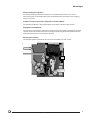
Spring-charging Motor (MCH)
The spring-charging motor automatically charges the stored energy mechanism (when the circuit
breaker closes) making O–C–O cycles possible without recharging. Opening and closing operations
are instantaneous.
Control Voltage (V)
06313048
Consumption
60 Hz
120–240
DC
24–48–125
AC
180 VA
DC
180 W
Inrush Current
2 to 3 x In for 0.1 sec.
Charging Time
3 to 4 sec.
Spring
Charged
262
B4
M
CH
B1
Operation Counter (CDM)
With spring-charging motor option only. The operation counter is read from the front and gives the
total number of circuit breaker operating cycles.
Spring-charged Switch
This type "b" switch is closed when the spring is charged. It comes standard with the spring
charging motor and is provided with a common terminal.
Max. Current (A)
60 Hz
240 V
10
DC
125 V
0.5
250 V
0.25
24
©1995 Square D—All Rights Reserved
11/98
06313049
Accessories
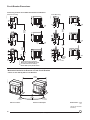
Closing Coil (XF)
06313050
This device releases the circuit breaker closing mechanism when the spring is charged. The closing
coil is rated for continuous duty. The closing release is supplied on request and can be fitted even
on a manual operating mechanism.
Remote
Close
A4
XF
A1
Anti-pumping Function
When the closing coil (XF) is permanently energized, the circuit breaker remains in the open
position after it has been opened, either by manual or electrical operation. The circuit breaker can
only be closed if the closing coil is momentarily de-energized (see p. 32).
Note: This anti-pumping function can be disabled by series connecting a ready-to-close ("b" contact)
switch (PF) to the closing coil.
Circuit Breaker Closing Time
Less Than 80 ms
Operating Voltage Range
0.85 to 1.1 x Rated Voltage
Control Voltage (V)
60 Hz
Consumption (Inrush and Sealed)
120–240
DC
24–48–125
60 Hz
20 VA
DC
15 W
25
11/98
©1995 Square D—All Rights Reserved
Accessories
Opening Coils
Three types of voltage releases can be used for remote opening of the circuit breakers:
n Shunt trip (MX)
n Instantaneous undervoltage trip device (MN)
n Time-delayed undervoltage trip device (MNR)
Possible Combinations
06313049
Each MASTERPACT circuit breaker can be equipped with:
n One shunt trip (MX) + one undervoltage trip device (MN or MNR)
n Or two shunt trips (MX)
Shunt Trip (MX)
This release is rated for continuous duty and operates with control voltages between 85% and 110%
of its rating. However, when series connected with an "a" auxiliary switch, the shunt trip can be
operated with 55% or more of its rated voltage and can be used for ground-fault protection when
combined with a Class 1 ground-fault sensing element. The shunt trip is field-installable.
Control Voltage (V)
60 Hz
120–240–480
DC
24–48–125–250
Consumption (Inrush and Sealed)
06313051
Operating Time
AC
20 VA
DC
15 W
40 ms
Remote
Open
C2
MX
C1
Instantaneous Undervoltage Trip Device (MN)
06313052
This release instantaneously opens the circuit breaker when supply voltage drops below a value
between 35% and 70% of rated voltage. If the release is not energized, the circuit breaker cannot
be closed (either manually or electrically). Any attempt to close it will have no effect on the main
contacts. Closing is possible when the release voltage reaches 85% of its rated value. The
instantaneous undervoltage trip device is field-installable.
Remote
Open
D4
MN
D1
26
©1995 Square D—All Rights Reserved
11/98
Accessories
Time-delayed Undervoltage Trip Device (MNR) (1)
To prevent the circuit breaker from tripping in the event of transient voltage drops, this release has a
built-in adjustable time delay. If required, this time delay can be overridden by connecting an
external switch on an additional circuit (wired by the user). The undervoltage trip device is fieldinstallable.
MN
MNR (1)
Control Voltage (V)
60 Hz
DC
120
120
240
—
480
480
24
—
48
—
125
—
250
—
Consumption (Inrush and Sealed)
AC
20 VA
20 VA
DC
15 W
15 W
0.09
0.5–0.9–1.5–3
Operating Time (s)
(1) Not UL Listed.
06313053
Heavy Usage Auxiliary Switches (OF)
06313054
Four SPDT switches with double break construction. They are directly operated by the main
contacts and ensure a large insulation distance in open position. They are therefore particularly
suitable for insulation of auxiliary circuits or reliable interlockings.
n "a" contacts are open when the circuit breaker is open and closed when the circuit breaker is
closed.
n "b" switches are closed when the circuit breaker is open and open when the circuit breaker is
closed.
See page 30 for operating diagrams. Auxiliary switches are field-installable.
Closed
Open
12
14
22
24
32
34
42
44
OF
11
21
31
41
27
11/98
©1995 Square D—All Rights Reserved
06313055
Accessories
24 Additional Auxiliary Switches (OFSUP)
An external plate holds a set of 24 SPDT switches operated by means of a cable. They are
available only for drawout circuit breakers.
Standard Auxiliary Switches (O and F)
06313056
2a + 2b switches available as standard:
n "a" contacts are open when the circuit breaker is open and closed when the circuit breaker is
closed.
n "b" switches are closed when the circuit breaker is open and open when the circuit breaker is
closed.
See page 30 for operating diagrams.
Open
Closed
212
222
234
244
F
F
O
O
211
221
231
241
Ready-to-close Switch (PF)
06313057
This SPDT switch indicates that the circuit breaker is ready to close and that the following
conditions exist:
n The circuit breaker is open
n The stored energy mechanism is charged
n The control unit is reset
n The circuit breaker opening push button is neither locked nor padlocked
n The circuit breaker is in the fully-connected or test position
The switch is field-installable.
Ready-to-Close
252 254
PF
251
28
©1995 Square D—All Rights Reserved
11/98
Accessories
Connected Position Switches (CE)
A block of four SPDT switches operate when a drawout circuit breaker is in the connected position.
The switch block is field-installable.
Disconnected Position Switches (CD)
A block of two SPDT switches operate when a drawout circuit breaker is in the disconnected
position. The switch block is field-installable. See page 30 for operating diagrams.
Test Position Switch (CT)
06313059
06313058
One SPDT switch is operated only when the circuit breaker is in the test position. The switch is fieldinstallable.
Connected Position Switches (CE)
06313060
Disconnected Position Switches (CD)
Disconnected
Connected
314
312
324
311
322
Test
334
321
332
344
342
321
321
352
354
351
362
364
372
374
361
371
Connection by 1/4 in. Male Quick Connect Terminal
Current Ratings (A)
Voltage (V)
Heavy Usage
60 Hz
DC
240
10
480
600
Auxiliary Switch
Ready-to-close
Standard 24 Additional Switch
15
15
10 (1)
6
6
3
125
3
250
3
12
Connected
Position Switch
Disconnected
Test
15
15
15
6
6
6
6
3
3
3
3
0.5
0.5
0.5
0.5
0.5
0.25
0.25
0.25
0.25
0.25
See page 65 for IEC voltage ratings.
(1) 8 A for MC08.
29
11/98
©1995 Square D—All Rights Reserved
Accessories
Operating Diagrams
Auxiliary Switches
06313061
0
1
2
inch
0
1
2
3
4
5
mm
Fully
Closed
Fully
Open
Closed
Main Contact Position
13/8 in. (35 mm)
Between Contacts
Open
Closed
a
Heavy Usage (OF)
.1
Standard (O)
.1
Standard (F)
.1
24 Additional (OFSUP)
.1
b
a
b
b
a
.4
3/8 in. (9.5 mm)
Between Contacts
in Open Position
Open
Open
.2
Closed
.4
Closed
Open
.2
Open
Closed
.4
Closed
Open
Open
Closed
.2
Note: Contacts are shown with the circuit breaker in the open position. Scale applies only to
distance between main contacts.
06313062
Position Switches
Disconnected
Test
Connected
Main Disconnect
Position
Isolation Distance (1 in. [25.4 mm] or More)
Secondary Disconnect
Position
Isolation Distance (1/2 in. [13 mm] or More)
Connected
Connected
b
Connected Position
Switches (CE)
.1
a
b
Disconnected Position
Switches (CD)
.1
Test Position Switches
(CT)
.1
a
b
a
.4
.2
.2
.4
Closed
Open
Open
Closed
Closed
Open
Open
Closed
Open
Closed
Open
Closed
.4
.2
Open
Closed
Note: Position switches are shown with the circuit breaker in the connected position.
30
©1995 Square D—All Rights Reserved
11/98
Accessories
Push Button Locking Device (VBP)
This device prevents local manual operation of the circuit breaker by covering the opening and/or
closing the push buttons. This locking device can be locked by a padlock or a sealing lead.
Open Position Lock (VSKA)
06313063
06313064
A key interlock that locks the circuit breaker in the open position by holding the push button in its
depressed position. The key interlock is provided.
06313065
Push Button Locking Device (VBP)
Open Position Lock (VSKA)
Door Interlock (VPEC)
This lock prevents the compartment door from being opened when the circuit breaker is in the
connected position. If the circuit breaker is put into the "connected" position with the door open, the
door can be closed without disconnecting the circuit breaker.
Note: For greater protection, this interlock can be used with racking interlock (VPOC) below.
Racking Interlock (VPOC)
This lock prevents racking in the circuit breaker when the door is open. (Insertion of the circuit
breaker racking crank is not possible when the compartment door is open.)
Disconnected Position Locking
The circuit breaker can be locked in the disconnected position by means of one to three padlocks
(padlocks not provided) or one key interlock (factory-mounted option VSKC). The key interlock is on
the stationary assembly and accessible with the cubicle door locked.
Note:
n Key interlock is of the captive key type, free when locked.
n By special order, locking may be possible on disconnected, test and connected positions
(VSKEC).
Spring Charge Interlock (VEAA)
This selection is for a device that prevents the circuit breaker or switch from being fully withdrawn
from its cradle when the closing spring is charged. It is standard for ANSI (UL1066) circuit breakers
and an option on others. The VEAA interlock is not compatible with undervoltage releases (MN,
MNR or MNRI).
31
11/98
©1995 Square D—All Rights Reserved
Accessories
Mechanical Interlocks
n Disconnecting When Circuit Breaker Is Closed:
During any disconnecting attempt when the circuit breaker is closed, an interlocking device
ensures the tripping of the circuit breaker before the actual separation of the main disconnects.
The circuit breaker remains, however, operable in the other positions: test, disconnected and
withdrawn.
n Circuit Breaker Closing When Not Completely Connected:
The interlocking device mentioned above prevents closing of the circuit breaker if the connecting
operation is not completely achieved.
n Connecting Circuit Breaker When Door Opened:
VPEC and VPOC options prevent the compartment door from being opened when the circuit
breaker is in the connected position and from connecting the circuit breaker when the door is
open.
Electrical Interlocks
n Priority of Opening Orders (Standard):
06313066
Opening coils (undervoltage trip devices, shunt trip) and opening push button have priority over
the closing coils and closing push button.
n Mechanical Pop-out Type Indicator (Standard):
Under overcurrent or ground-fault conditions, the trip indicator located in the control unit will pop
out. It is not possible to close the circuit breaker until this trip indicator is reset. This standard
function can be disabled upon request.
n Anti-pumping Function (Standard):
In case the closing coil (XF) becomes permanently energized, the circuit breaker remains in the
open position A after it has been opened, either by manual or electrical operation. The circuit
breaker can be closed only if the closing coil is momentarily de-energized B.
Note: This anti-pumping function can be disabled by series connecting a "ready to close" (NC
contact) switch (PF) with the closing coil (XF).
Closing Coil
ON
ON
OFF B
OFF
Shunt Trip (same anti-pumping function with undervoltage trip device)
ON
OFF
OFF
Circuit
Breaker Status
ON
ON
Without
Anti-pumping
Function
OFF
OFF A
32
©1995 Square D—All Rights Reserved
11/98
Accessories
06313067
Interlocking Rods and Cables
Two or three MASTERPACT circuit breakers can be mechanically interlocked by means of rods or
cables. This accessory is mountable on the right side of the circuit breaker. This adaptation can be
made on site without modifying the circuit breaker.
Mechanical Interlock Between Two or Three Stacked Circuit Breakers
This interlocking is obtained by the joining of:
n One adaptation block
n One or two adjustable and nonadjustable rods
Maximum distance between the two fixing surfaces of the devices: 35 in. (0.89 m)
Mechanical Interlocks Between Two Side-by-Side Circuit Breakers
This interlocking is obtained by the joining of:
n One adaptation block
n One set of adjustable cables with a maximum length of 78 in. (2 m)
Possible Mounting Arrangements Among Three Stacked Circuit Breakers
06313068
One use, power supplied by:
n Two transformers N1 and N2 which are connected in parallel
n Or one standby source G
N1
N2
G
06313069
Two uses, independently powered supply by two transformers N1 and N2, standby through a circuit
breaker or a connection tie switch, preventing the connection in parallel of the two current
transformers.
N1
N2
C
06313070
One use, power supplied by one group of transformers N1, N2 or N3 or of generators, preventing
any connection in parallel.
N1
N2
N3
33
11/98
©1995 Square D—All Rights Reserved
Accessories
Safety Shutters (VO)
Comprising two independent parts, line and load side, the safety shutters automatically block
access to the main disconnects when the circuit breaker is in the disconnected, test or fully
withdrawn position.
Shutters Lock (VVC)
06313072
06313071
A factory-mounted movable and lockable slide (padlock not supplied) is used to:
n Lock the line or load shutters in the closed position
n Hold the line or load shutters in the open position
A support is provided at the back of the stationary assembly to hold the slide when not in use.
Safety Shutters
Shutters Lock
Rejection Feature (VDC)
06313074
06313073
The rejection feature ensures that only the properly designated circuit breaker is matched with the
selected cradle assembly. It is made of two parts (one for the frame and one for the stationary
assembly), and allows 20 different combinations.
2
4
6
A
B
1
3
D
5
F
Stationary
Assembly
C
E
Circuit Breaker
Frame
Possible Arrangements
Frame
Stationary
Assembly
Frame
Stationary
Assembly
A–B–C
4–5–6
B–C–D
1–5–6
A–B–D
3–5–6
B–C–E
1–4–6
A–B–E
3–4–6
B–C–F
1–4–5
A–B–F
3–4–5
B–D–E
1–3–6
A–C–D
2–5–6
B–D–F
1–3–5
A–C–E
2–4–6
B–E–F
1–3–4
A–C–F
2–4–5
C–D–E
1–2–6
A–D–E
2–3–6
C–D–F
1–2–5
A–D–F
2–3–5
C–E–F
1–2–4
A–E–F
2–3–4
D–E–F
1–2–3
34
©1995 Square D—All Rights Reserved
11/98
Accessories
Interphase Barrier (EIP)
Mounted between terminals of the stationary assembly, the interphase barrier prevents arc
prolongation to the circuit breaker in the event of a line side fault and isolates the circuit breaker
connections in insulated bus bar installations.
Transparent Cover (CB)
06313076
06313075
Hinged-mounted and locked with a milled head, this cover is designed to be installed on the door
escutcheon. It provides a higher degree of protection and is suitable for drawout or fixed-mounted
circuit breakers.
Interphase Barrier
Transparent Cover
35
11/98
©1995 Square D—All Rights Reserved
06313077
Switch
Ratings
Type
Ampere
Rating
(A)
Short-time Rating
(RMS Sym. Amperes)
600 Vac Max.
Short-circuit Withstand When
Protected by a MASTERPACT
Circuit Breaker (A)
Max. Frame (A)
600 Vac Max.
MP08 NA
800
50,000
800
50,000
MP12 NA
1200
50,000
1200
50,000
MP16 NA
1600
50,000
1600
50,000
MP20 NA
2000
50,000
2000
50,000
MP25 NA
2500
50,000
2500
50,000
MP30 NA
3000
50,000
3000
50,000
MP40 NA
4000
85,000
4000
85,000
MP50 NA
5000
85,000
5000
85,000
MP63 NA (1)
6300
85,000
6300
85,000
(1) Not UL Listed.
CAUTION
HAZARD OF EQUIPMENT DAMAGE.
This switch contains no overcurrent protection.
It is suitable for use at its ampere rating when
protected by a MASTERPACT circuit breaker
of the same ampere rating.
Failure to observe this precaution can
cause equipment damage.
Construction
The MASTERPACT switch is identical to the MP circuit breaker, except that the switch is not
equipped with current transformers or an actual control unit. However, it does have an STR08
dummy unit.
Accessories, Dimensions and Connections
Switch accessories, dimensions and connections are identical to those of the corresponding circuit
breaker, except that the overcurrent trip switch is not available with the switch version.
Page
Accessories
23
Wiring diagrams
42
Circuit Breaker Dimensions
46
36
©1995 Square D—All Rights Reserved
11/98
Trip Curves
9000
8000
7000
6000
5000
5000
4000
4000
3000
3000
Current Setting:
STR 28D = 0.4–1 x Sensor Rating
STR 28DP = 0.8–1 x Plug Rating
2000
2000
1000
900
800
700
600
1000
900
800
700
600
500
500
400
400
300
300
200
200
100
90
80
70
60
100
90
80
70
60
50
50
40
40
30
30
20
20
10
9
8
7
6
10
9
8
7
6
5
5
4
4
3
3
2
2
Instantaneous Pickup
I = 1.5–10 x Ir
1
.9
.8
.7
.6
1
.9
.8
.7
.6
.5
.5
.4
.4
.3
.3
.2
.2
.1
.09
.08
.07
.06
.1
.09
.08
.07
.06
.05
.05
.04
.04
.03
.03
.02
.02
Multiple of Current Setting (Ir)
6000
7000
8000
9000
10000
40 50 60
5000
30
4000
20
3000
6 7 8 9 10
2000
5
600
700
800
900
1000
4
500
3
400
2
300
.5 .6 .7 .8 .9 1 1.2 1.5
200
.01
.01
70
80
90
100
Time in Seconds
6000
7000
8000
9000
10000
40 50 60
5000
30
4000
20
3000
6 7 8 9 10
2000
5
600
700
800
900
1000
4
500
3
400
2
300
.5 .6 .7 .8 .9 1 1.2 1.5
200
10000
9000
8000
7000
6000
70
80
90
100
06313078
Overcurrent Protection STR 28D Control Unit
37
11/98
©1995 Square D—All Rights Reserved
Trip Curves
.5 .6 .7 .8 .9 1 1.2 1.5
2
3
4
5
6 7 8 9 10
20
30
40 50 60
2
3
4
5 6 7 8 9 10
20
30
40 50 60
70
80
90
100
10000
9000
8000
7000
6000
70
80
90
100
06313079
Overcurrent Protection STR 38S Control Unit
9000
8000
7000
6000
5000
5000
4000
4000
3000
3000
Current Setting:
STR 38S = 0.4–1 x Sensor Rating
STR 38SP = 0.8–1 x Plug Rating
2000
2000
Time in Seconds
2
1000
900
800
700
600
1000
900
800
700
600
500
500
400
400
300
300
200
200
100
90
80
70
60
100
90
80
70
60
50
50
40
40
30
30
20
20
10
9
8
7
6
10
9
8
7
6
5
5
4
4
3
3
2
2
Short-time Pickup
Im = 1.5–10 x (Ir)
I2 t ON
Inst (*)
1
.9
.8
.7
.6
1
.9
.8
.7
.6
.5
.5
.4
.4
.3
.3
0.3
0.3
.2
0.2
0.2
0.1
0.1
I2 t OFF
.1
.09
.08
.07
.06
.2
.1
.09
.08
.07
.06
0
.05
.05
.04
.04
.03
.03
.02
.02
2
3
4
5
6 7 8 9 10
20
30
40 50 60
2
x Ir
In (A)
I = In x …
630
28
800/1000
28
3
4
5 6 7 8 9 10
20
30
40 50 60
70
80
90
100
.5 .6 .7 .8 .9 1 1.2 1.5
70
80
90
100
.01
.01
(*) Instantaneous
Rating
Fixed Threshold
0.4
x In
1200/1600
24
2000
20
2500
14
3000/3200
12
4000/5000/6300
10
38
©1995 Square D—All Rights Reserved
11/98
Trip Curves
2
3
4
5
6 7 8 9 10
20
30
40 50 60
2
3
4
5 6 7 8 9 10
20
30
40 50 60
9000
8000
7000
6000
9000
8000
7000
6000
5000
5000
4000
4000
3000
3000
Current Setting:
STR 58U = 0.4–1 x Sensor Rating
STR 58UP = 0.8–1 x Plug Rating
2000
1000
900
800
700
600
1000
900
800
700
600
500
500
400
400
300
300
200
200
100
90
80
70
60
100
90
80
70
60
50
50
40
40
30
30
20
20
10
9
8
7
6
10
9
8
7
6
5
5
Short-time Pickup
Im = 1.5–10 x (Ir)
4
3
H1: 2–4–8–12–14–19–22–Off
H2: 2–4–8–12–14–19–22–Max.
1200/1600 A
H1: 2–4–8–12–14–17–22–Off
H2: 2–4–8–12–14–17–22–Max.
2000 A
2
I 2 t ON
1
.9
.8
.7
.6
1
.9
.8
.7
.6
.5
.5
.3
.2
H1: 2–4–6–8–10–12–12–Off
H2: 2–4–6–8–10–12–12–Max.
I 2 t OFF
.1
.09
.08
.07
.06
.05
3000/3200 A
H1: 2–4–6–8–10–10–10–Off
H2: 2–4–6–8–10–10–10–Max.
4000/5000/6300 A
H1: 2–4–6–8–8–8–8–Off
H2: 2–4–6–8–8–8–8–Max.
0.4
.4
0.3
0.3
.3
0.2
0.2
0.1
0.1
.4
H1: 2–4–8–10–12–14–17–Off
H2: 2–4–8–10–12–14–17–Max.
2500 A
3
2
.1
.09
.08
.07
.06
.05
.04
.03
.03
.02
.02
.01
.5 .6 .7 .8 .9 1 1.2 1.5
2
3
4
5
6 7 8 9 10
20
30
40 50 60
2
x Ir
(*) Instantaneous
Rating
In (A)
Maximum Threshold I = In x
.2
Instantaneous Pickup
I = 2 x In Max (*)
.04
70
80
90
100
800/1000 A
4
630
28
800/1000
28
3
4
5 6 7 8 9 10
20
30
40 50 60
.01
70
80
90
100
Time in Seconds
2000
Instantaneous Dial
Settings
70
80
90
100
.5 .6 .7 .8 .9 1 1.2 1.5
70
80
90
100
06313080
Overcurrent Protection STR 58U Control Unit
x In
1200/1600
24
2000
20
2500
14
3000/3200
12
4000/5000/6300
10
39
11/98
©1995 Square D—All Rights Reserved
Trip Curves
3
4
5
6 7 8 9 10
20
30
40 50 60
600
700
800
900
1000
2
1000
900
800
700
600
Ground-fault Pickup
Ih = 0.1 x In 1200 A Max.
500
400
500
400
300
300
200
200
100
90
80
70
60
100
90
80
70
60
50
50
40
40
30
30
20
20
10
9
8
7
6
10
9
8
7
6
5
5
4
4
3
3
I 2t ON
2
Time in Seconds
.5 .6 .7 .8 .9 1 1.2 1.5
500
.4
400
.3
300
.2
200
.1 .12 .15
70
80
90
100
1000
900
800
700
600
.05
.06
.07
.08
.09
06313081
Ground-fault Protection STR 38S–STR 58U Control Units
2
1
.9
.8
.7
.6
1
.9
.8
.7
.6
.5
.5
.4
0.4
.4
.3
0.3
.3
.2
0.2
.2
I2t OFF
.1
.09
.08
.07
.06
.1
.09
.08
.07
.06
0.1
.005
.005
.004
.004
.003
.003
.002
.002
.001
.001
.1 .12 .15
.2
.3
.4
.5 .6 .7 .8 .9 1 1.2 1.5
2
3
4
5
6 7 8 9 10
20
30
40 50 60
600
700
800
900
1000
.01
.009
.008
.007
.006
500
.01
.009
.008
.007
.006
400
.02
300
.03
.02
200
.04
.03
70
80
90
100
.05
.04
.05
.06
.07
.08
.09
.05
Multiple of Current Sensor (In)
40
©1995 Square D—All Rights Reserved
11/98
Trip Curves
10000
9000
8000
7000
6000
2
3
4
5
6 7 8 9 10
20
30
40 50 60
10000
9000
8000
7000
6000
5000
5000
4000
4000
3000
3000
Current Setting
Ir = 0.8–1 x Plug Rating
2000
2000
1000
900
800
700
600
Ic1 = 0.8 1 x Ir
1000
900
800
700
600
500
Ic2 = 0.5 1 x Ir
500
400
400
300
300
200
200
100
90
80
70
60
100
90
80
70
60
tr1 = tr / 2
50
50
40
40
30
30
tr2 = tr / 4
5
4
4
3
3
2
2
1
.9
.8
.7
.6
1
.9
.8
.7
.6
.5
.5
.4
.4
.3
.3
.2
.2
.1
.09
.08
.07
.06
.1
.09
.08
.07
.06
.05
.05
.04
.04
.03
.03
.02
.02
.1 .12 .15
.2
.3
.4
.5 .6 .7 .8 .9 1 1.2 1.5
2
3
4
5
6 7 8 9 10
20
30
40 50 60
.01
600
700
800
900
1000
.01
500
5
400
10
9
8
7
6
300
10
9
8
7
6
200
20
70
80
90
100
20
.05
.06
.07
.08
.09
Time in Seconds
600
700
800
900
1000
.5 .6 .7 .8 .9 1 1.2 1.5
500
.4
400
.3
300
.2
200
.1 .12 .15
70
80
90
100
.05
.06
.07
.08
.09
06313082
Load Monitoring STR 58U Control Unit
Multiple of Current Setting (Ir)
41
11/98
©1995 Square D—All Rights Reserved
Wiring Diagrams
06313083
Diagram No. 689 889
Drawout Position Switches
Connected
Auxiliary Switches
Disconnected
Test
Standard
Remote Operation
Heavy
Duty
Undervoltage
Trip Device or
Closed
Disconnected
Motor
Operator
Spring
Charged
Open
Remote
Close
314 312 324 322 334 332 344 342 352 354 362 364 372 374
212 222 234 244
321
Ready
to Close
Remote
Open
Test
Connected
311
Shunt
Trip
331
341
351
361
12 14
22 24
32 34
42 44
D4
C2
A4
252 254
262 B4
371
MN
Standard
211 221 231 241
MX
XF
OF
11
21
31
PF
41
D1
C1
A1
CH
251
Note: Circuit breaker shown in connected, charged and open position with undervoltage releases energized.
42
©1995 Square DÑ All Rights Reserved
11/98
B1
Wiring Diagrams
06313084
Diagram No. 689 889
Remote Fault
and Overload
Indication
Ground-fault
Protection
Ammeter
Local Fault Indications
and Remote Selected
Fault Indication
Zoneselective
Interlocking
Load
Monitoring
Data
Transmission
Ic2
Fault
Alarm
Selected
Fault
Overload
Alarm
Ic1
Upstream
Circuit
Breaker
82 84 (1)
LR2
S2
S1
T2
T1
Z11
LT
1
I Option
LT
Alarm
SDE
81
F1
_
(5)
F2
Z12
Gnd
R1 R2
Z Option
F or FV Option
e+
e–
Out
T or W Option
(4)
LR1
ST
Communication (3)
Network
(6)
C Option
R Option
In
V
Z21
Z22
C
+
(2)
24 Vdc
(1) 84 terminal not available with Z or C option.
(2) Zone-selective interlocking with downstream circuit breaker: remove
the jumper.
(3) Communication output through DIGIPACT module.
(4) Use 24 Vdc supply for loads less than 20% of current sensor
rating, or one-phase load less than 40% of sensor rating.
Downstream
Circuit
Breaker
(5) Use 24 Vdc supply for lower setting.
(6) Use 24 Vdc supply for F option if not supplied with PIL (battery)
option; use 24 Vdc supply (mandatory) for FV option.
43
11/98
©1995 Square D—All Rights Reserved
Wiring Diagrams
SC150 Indication and Control Interface
Motor
Operator
Power Supply
06313085
To Power
Supply "L"
400
630
C1 NO NC ON C2 reset
Control Outputs
C3 CD CE SDV SD
Inputs
PT100
Temperature
Probe
External
Contact
24-250V CC
100-440V CA
2
DIGIPACT
Internal Bus
COM
+ – NC 0 24V e+ e– T+ T–
SC150 Indication and Control Interface
Inputs
C4 ON IN OFFSDE
L
To "IN"
SC150
Input
Terminals
1 4
To "C4"
SC150
Input
Terminals
N
To SC150
Terminals
"T+" and "T–"
To "C3"
on SC150
Input Terminals
To "C4"
on SC150
Input Terminals
To "CD"
on SC150
Input
Terminals
To "SDE"
on SC150
Input Terminals
To "OFF"
on SC150
Input Terminals
To "ON"
on SC150
Input Terminals
To "CE"
on SC150
Input
Terminals
2 1 4
2 1 4
2 1 4
CE
CD
Control Unit
STR28 / 38 / 58
To "ON"
SC150 Control
Output Terminals
to "NO"
SC150 Control
Output Terminals
To Power Supply "L"
A4 C2 B4
Remote
Control
2 1
SDE
Control Unit
STR58U
Control Unit
To "e +" and "e –"
on SC150
"COM" Terminals
XF MX M
C1
To Auxiliary
Source
e+ e –
SDE
A1
2 1 4
To "SDE"
on SC150
Input Terminals
2 1 4
OF
To "C4"
on SC150
Input Terminals
B1
To Power Supply "N"
MASTERPACT Circuit Breaker
Internal Bus
Marking
Color
24 V
Red
0V
Black
Internal Bus –
White
Internal Bus +
Blue
44
©1995 Square D—All Rights Reserved
11/98
Wiring Diagrams
DC150 Data Concentrator
06313086
DC150
9600
3456
2
2
1
110–240 Vac
115–125 Vdc
A
Protection
5
0
78 9A
B CD
N°2
3456
B
78 9A
0
E
N°1
B CD
Internal
Bus
NC
Internal Bus –
Internal Bus +
MODBUS/JBUS
Speed
19200
B
E
24 V
0V
DC150 Address
on MODBUS/JBUS
Network
6
9
RS485
MODBUS/JBUS
C
Connectors
06313088
The DC150 concentrator is connected using a SUBD9 male connector with a metal hood (e.g., ITT
canon, DE9P K83 + hood or DE115-500-5-RD). The DC150 concentrator is equipped with a SUBD9
female connector. For a multidrop configuration, the tap-offs can be made either via a branching off
of RS485 connector Catalog No. 50788 or standard connection boxes, taking care to respect the
necessary precautions when connecting the shieldings. The adaptation of an RS232 output on a
personal computer to accept the RS485 standard connector should be done with the RS485/RS232
converter Catalog No. 50786.
1
06313087
6
0V
5V
2
1
0V
7
6
Rp
Rp
3
2
8
7
Rc
4
3
RD+ (A')
9
8
RD– (B')
5
4
TD+ (A)
L+ (A / A')
L– (B / B')
9
TD– (B)
5
Recommended Protection and Cable Sizes
DC150 Concentrator with
Polarization and 2-wire
Adaptation
Recommended
Protection
Type
Catalog No.
C60N Supplementary Circuit Protector
Curve C–10 A
3-Phase
MG24466 or 24214
Fuse-link 10 A
aM
15660
Marking (1)
Connection
Cable
A
Voltages
0.06 to 0.1 in.2 (0.75 to 2.5 mm2)
B
Internal Bus
0.03 to 0.1 in.2 (0.75 to 2.5 mm2) (Twisted)
C
MODBUS/JBUS
0.03 to 0.1 in.2 (0.75 to 2.5 mm2) (Shielded)
Internal bus
Marking
Color
24 V
Red
0V
Black
Internal Bus –
White
Internal Bus +
Blue
(1) See first drawing above.
45
11/98
©1995 Square D—All Rights Reserved
Circuit Breaker Dimensions
Door Escutcheon (Drawout Mounting)
Drilling of the Door
06313091
06313089
06313090
Door Cutout
6
153
10.63
270
0.75
Basis:
19
MP08 to MP30
2.6 MC08 to MC32
66
1.85
47 1.77
2.17
45
55
12.8
325
2.82
72
MP40 to MP63
MC40/MC50
5.83
0.73 149
19
2.72
69
Mounting
Holes
0.19 Dia.
∅5
7.1
180
7.1
180
0.69/ 18
Door Escutcheon (Fixed Mounting)
Drilling of the Door
06313094
06313093
06313092
Door Cutout
6
153
10.63
270
2.82
2.82
72
72
2.72
69
1.06
27
Mounting
1.48 Holes
38
12.8
325
0.57 5.83
15 149
0.19 Dia.
∅5
7.1
180
7.1
180
0.69
18
Note: Refer to shop drawings for verification.
Rear Cutout
≤0.15
4
0.79
20
0.15
4
06313097
06313095
06313096
Door Interlock
14.2
360
0.80
20
0.12
3
14.5/368 MP30
29.4/748 MP50/MC50
38.4/978 MP63
1.69
43
0.12
3
Circuit
Breaker
Base
Mounting
Holes
17.5
445
2.36
60
Note: The door interlock can be mounted on
either the right side or the left side of the circuit
breaker.
Dimensions: inch
mm
46
©1995 Square D—All Rights Reserved
11/98
Circuit Breaker Dimensions
External Neutral Sensor
0.7
18
0.7
18
3.15
80
1.75
45
MP25/MP30/MP40, MC32/MC40
06313099
06313098
MP08 to MP20, MC08 to MC20
0.56 Dia.
∅14
0.39/10
MP08 to MP16
MC08 to MC16
1.73
44
0.79/20
MP20/MC20
1.75
45
0.79
20
3.94
100
6.30
160
2.36
60
1.75
45
0.7
18
1.8
46
0.78
20
4.72
120
0.7
18
3.15
80
1.75
45
06313101
06313100
0.7
18
0.56 Dia.
∅14
2.9
74
0.79/20
MP25/MP30/MC32
3.31
84
1.18/30
MP40/MC40
1.75
45
0.79
20
3.94
100
6.30
160
2.36
60
1.75
45
0.7
18
1.8
46
0.78
20
4.72
120
4.5
114
0.58
15
7.47
190
1.17
30
2.11
54
0.54
14
9.12 / 9.41
235 / 240
6.27
160
1.57
40
0.47 Dia.
Ø12
4.7
120
06313104
0.58
15
06313103
06313102
MP50 to MP63
0.58
15
2.35
60
=
3.13
80
2.35
60
8.62
220
0.68
17.5
0.78
20
3.5
89.5
2.19
56
1.17
30
=
=
= =
7.84
200
=
=
0.98
25
7.84
200
Dimensions: inch
mm
47
11/98
©1995 Square D—All Rights Reserved
Circuit Breaker Dimensions
MP08–MP12–MP16 Fixed Mounting
4.53
115
4.53
3.35
115
85
3.15
0.98 80 0.98
25
25 0.47 Dia.
∅12
06313106
06313105
3-Pole
4.53
115
0.5 Dia.
∅12,7
4.53
115
Note: Suitable for
continuous operation at
100% rating in a
minimum cubicle space
17.5 in. (440 mm) h. by
21 in. (530 mm) w. by
14.25 in. (360 mm) d.
Ventilation is not
required. Refer to shop
drawing #688 378 for
verification. Vertical
terminals are optional
for MP08–MP12 circuit
breakers.
3.35
85
0.63
16
Necessary Space for Removing the Arc Chutes
3.15
80
06313108
06313107
14.88
378
17.24
438
Cell (Insulation Not Required)
1.57
40 Min.
0.69
17,5
(4) Mounting
Holes
0.44 Dia. / Ø11
1
25,4
4.41
112
5.59
142
3.15
80
2.08
53
0.43
11
15.75
400
0.43
11
16.61
422
2.83
72
1.18 / 30 Min.
2.36 / 60 Max.
5.91
150
2.68
68
9.17
233
11.14
283
15.78
401
0.39
10
0.19 1.69
3 43
0.49
12,5
0.71
18
0.98
25
4.53
115
4.53
4.53
115 3.15115
80
3.35
85
0.47 Dia.
Ø12
0.63
16
4.53
115
4.53
115
4.53
115
3.35
85
0.5 Dia.
Ø12,7
06313110
06313109
4-Pole
19.4
493
3.15
80
21.8
553
Cell (Insulation Not Required)
1.57
40 Min.
06313112
06313111
Necessary Space for Removing the Arc Chutes
0.69
17,5
(4) Mounting
Holes
0.44 Dia. / Ø11
20.2
515
0.43
11
2.83
72
1.18 / 30 Min.
2.36 / 60 Max.
5.91
150
2.68
68
9.17
233
11.14
283
15.78
401
0.39
10
1
25,4
4.41
112
5.59
142
3.15
80
2.08
53
0.43
11
Note: Suitable for
continuous operation at
100% rating in a
minimum cubicle space
17.5 in. (440 mm) h. by
25.5 in. (645 mm) w. by
14.25 in. (360 mm) d.
Ventilation is not
required. Refer to shop
drawing #691 378 for
verification. Vertical
terminals are optional
for MP08–MP12 circuit
breakers.
0.71
18
0.19 1.69
3 43
0.49
12,5
Dimensions: inch
mm
48
©1995 Square D—All Rights Reserved
11/98
Circuit Breaker Dimensions
MP08–MP12–MP16–MC08–MC16 Drawout Mounting
4.53
115
4.53
115
1.87
48
3.15
80
0.98
25
06313114
06313113
3-Pole
4.53
115
0.5 Dia.
∅12,7
4.53
115
Note: Suitable for
continuous operation at
100% rating in a
minimum cubicle space
17.5 in. (440 mm) h. by
21 in. (530 mm) w. by
14.25 in. (360 mm) d.
Ventilation is not
required. Refer to shop
drawing #688 378 for
verification. Vertical
terminals are optional
for MP08–MP12–MC08
circuit breakers.
1.87
48
0.63
16
0.47 Dia.
∅12
Withdrawn Position
9.56 1.77
243 45
Disconnected Position
14.21
361
06313115
06313120
Cell (Insulation Not Required)
0.69
18
0.98
25
1
25
0.39
10
5.98
152
3.15
80
3.23
82
4.41
112
3.62
92
(4) Mounting
Holes
0.44 Dia./∅11
12.8
325
17.14
435
2.17
55
3.98
101
4.21
107
2.17
55
6.89
175
3.35
85
11.81
300
17.32
440 Min.
1.65
42
0.49
13
13.78
350
0.49
13
Note: Suitable for
continuous operation at
100% rating in a
minimum cubicle space
17.5 in. (440 mm) h. by
25.5 in. (645 mm) w. by
14.25 in. (360 mm) d.
Ventilation is not
required. Refer to shop
drawing #691 381 for
verification. Vertical
terminals are optional
for MP08–MP12–MC08
circuit breakers.
4.53
115
0.98
25
4.53
4.53
115 3.15115
80
1.87
47,5
0.47 Dia.
Ø12
06313118
06313117
4-Pole
4.53
115
0.63
16
4.53
115
4.53
115
1.87
47,5
0.5 Dia.
Ø12,7
06313119
06313120
Withdrawn Position
9.56 1.77
243 45
Disconnected Position
14.21
361
Cell (Insulation Not Required)
21.89
556
0.98
25
0.39
10
(4) Mounting
Holes
0.44 Dia. / Ø11
4.41
112
3.62
92
2.75
70
16.73
425
21.65
550
2.17
55
3.98
101
4.21
107
6.89
175
3.35
85
11.81
300
13.78
350
0.49
13
0.69
18
1
25
17.32
440 Min.
5.98
152
3.15
80
3.23
82
1.65
42
0.49
13
Dimensions: inch
mm
49
11/98
©1995 Square D—All Rights Reserved
Circuit Breaker Dimensions
MP20 Fixed Mounting
Note: Suitable for
continuous operation at
100% rating in a
minimum cubicle space
17.5 in. (440 mm) h. by
21 in. (530 mm) w. by
14.25 in. (360 mm) d.
Ventilation is not
required. Refer to shop
drawing #688 379 for
verification.
06313121
3-Pole
4.53
115
0.79
20
0.56 Dia.
∅14
4.53
115
3.35
85
Necessary Space for Removing the Arc Chutes
17.24
438
3.15
80
06313123
06313122
14.88
378
Cell (Insulation Not Required)
1.57
40 Min.
4.53
115
(4) Mounting
Holes
0.44 Dia. / Ø11
0.43
11
15.75
400
5.98
152
3.15
80
0.43
11
16.61
422
15.78
401
1.75
44,5
2.83
72
1.18 / 30 Min.
2.36 / 60 Max.
5.91
150
2.68
68
0.71
18
14.98
380,5
0.12
3
1.75
44,5
1.69
43
06313124
4-Pole
0.79
20
4.53
115
4.53
115
4.53
115
3.35
85
Note: Suitable for
continuous operation at
100% rating in a
minimum cubicle space
17.5 in. (440 mm) h. by
25.5 in. (645 mm) w. by
14.25 in. (360 mm) d.
Ventilation is not
required. Refer to shop
drawing #691 379 for
verification.
0.56 Dia.
Ø14,3
19.4
493
3.15
80
06313123
06313125
Necessary Space for Removing the Arc Chutes
21.8
553
Cell (Insulation Not Required)
1.57
40 Min.
4.53
115
(4) Mounting
Holes
0.44 Dia. / Ø11
0.43
11
20.2
515
0.43
11
15.78
401
1.75
44,5
5.98
152
3.15
80
2.83
72
1.18 / 30 Min.
2.36 / 60 Max.
5.91
150
2.68
68
14.98
380,5
0.71
18
0.12
3
1.75
44,5
1.69
43
Dimensions: inch
mm
50
©1995 Square D—All Rights Reserved
11/98
Circuit Breaker Dimensions
MP20–MC20 Drawout Mounting
06313127
3-Pole
0.56 Dia.
∅14
4.53
115
0.79
20
4.53
115
Note: Suitable for
continuous operation at
100% rating in a
minimum cubicle space
17.5 in. (440 mm) h. by
21 in. (530 mm) w. by
14.25 in. (360 mm) d.
Ventilation is not
required. Refer to shop
drawing #688 379 for
verification.
1.87
48
06313129
Withdrawn Position
9.56 1.77
243 45
Disconnected Position
14.21
361
06313128
Cell (Insulation Not Required)
4.53
115
1.75
45
17.32
440 Min.
(4) Mounting
Holes
0.44 Dia./∅11
2.17
55
12.8
325
17.14
435
2.17
55
5.98
152
3.15
80
3.23
82
3.98
101
4.21
107
6.89
175
3.35
85
17.64
448
1.65
42
0.7
18
1.75
45
4-Pole
4.53
115
4.53
115
06313130
0.79
20
4.53
115
1.87
47,5
0.56 Dia.
Ø14,3
Note: Suitable for
continuous operation at
100% rating in a
minimum cubicle space
17.5 in. (440 mm) h. by
25.5 in. (645 mm) w. by
14.25 in. (360 mm) d.
Ventilation is not
required. Refer to shop
drawing #691 382 for
verification.
Withdrawn Position
9.56 1.77
243 45
Disconnected Position
Cell (Insulation Not Required)
06313129
06313131
14.21
361
21.89
556
4.53
115
1.75
45
17.32
440 Min.
(4) Mounting
Holes
0.44 Dia. / Ø11
2.75
70
16.73
425
21.65
550
2.17
55
5.98
152
3.15
80
3.23
82
3.98
101
4.21
107
6.89
175
3.35
85
17.64
448
1.75
45
1.65
42
0.7
18
Dimensions: inch
mm
51
11/98
©1995 Square D—All Rights Reserved
Circuit Breaker Dimensions
MP25–MP30 Fixed Mounting
06313133
3-Pole
0.56 Dia.
∅14
5.85
149
0.25
6
5.85
149
Note: Suitable for
continuous operation at
100% rating in a
minimum cubicle space
26 in. (660 mm) h. by
21 in. (530 mm) w. by
14.25 in. (360 mm) d.
with a ventilation of 30
sq. in. (200 cm2) at top
and bottom. Refer to
shop drawing #688 380
for verification.
2.01
51
0.25
6
14.88
378
17.24
438
3.15
80
06313138
06313134
Necessary Space for Removing the Arc Chutes
Cell (Insulation Not Required)
1.57
40 Min.
1.75
44,5
15.78
401
(4) Mounting
Holes
0.44 Dia. / Ø11
15.75
400
0.43
11
16.61
422
10.24
260
2.28
58
0.43
11
2.83
72
5.91 2.68
68
150
13.95
354,5
4.72
120
1.75
44,5
2.24
57
1.13 0.24
29
6
Note: Suitable for
continuous operation at
100% rating in a
minimum cubicle space
26 in. (660 mm) h. by
25.5 in. (645 mm) w. by
14.25 in. (360 mm) d.
with a ventilation of 30
sq. in. (200 cm2) at top
and bottom. Refer to
shop drawing #691 380
for verification.
06313136
4-Pole
5.85
149
4.55
115
0.25
6,35
0.56 Dia.
Ø14,3
5.85
149
2.01
51
0.25
6,35
06313137
19.4
493
06313138
Necessary Space for Removing the Arc Chutes
21.8
553
3.15
80
Cell (Insulation Not Required)
1.57
40 Min.
1.75
44,5
15.78
401
(4) Mounting
Holes
0.44 Dia. / Ø11
0.43
11
20.2
515
0.43
11
2.28
58
2.83
72
5.91 2.68
68
150
13.95
354,5
10.24
260
4.72
120
1.75
44,5
2.24
57
1.13 0.24
29
6
Dimensions: inch
mm
52
©1995 Square D—All Rights Reserved
11/98
Circuit Breaker Dimensions
MP25–MP30 Drawout Mounting
Note: Suitable for
continuous operation at
100% rating in a
minimum cubicle space
26 in. (660 mm) h. by
21 in. (530 mm) w. by
14.25 in. (360 mm) d.
with a ventilation of 30
sq. in. (200 cm2) at top
and bottom. Refer to
shop drawing #688 380
for verification.
3-Pole
06313139
0.56 Dia.
∅14
5.75
146
0.25
6
0.65
17
5.75
146
0.25
6
Withdrawn Position
06313144
9.56 1.77
243 45
Disconnected Position
14.21
361
06313140
Cell (Insulation Not Required)
2.28
58
1.75
44
17.32
440 Min.
10.24
260
(4) Mounting
Holes
0.44 Dia./∅11
12.8
325
17.14
435
2.17
55
4.72
120
2.17
55
3.98
101
4.21
107
6.89
175
3.35
85
1.75
17.64
448
45
1.30
0.71
1.14 33 18
29
Note: Suitable for
continuous operation at
100% rating in a
minimum cubicle space
26 in. (660 mm) h. by
25.5 in. (645 mm) w. by
14.25 in. (360 mm) d.
with a ventilation of 30
sq. in. (200 cm2) at top
and bottom. Refer to
shop drawing #691 380
for verification.
4-Pole
06313142
5.35
136
4.92
125
5.75
146
0.65
17
0.25
6,35
0.25
6,35
0.25
6,35
0.65
16,5
0.56 Dia.
Ø14,3
06313143
06313144
Withdrawn Position
9.56 1.77
243 45
Disconnected Position
14.21
361
21.89
556
Cell (Insulation Not Required)
2.28
58
1.75
44
17.32
440 Min.
(4) Mounting
Holes
0.44 Dia./ Ø11
10.24
260
4.72
120
2.75
70
16.73
425
21.65
550
2.17
55
3.98
101
4.21
107
6.89
175
3.35
85
17.64
448
1.75
45
1.30
0.71
1.14 33 18
29
Dimensions: inch
mm
53
11/98
©1995 Square D—All Rights Reserved
Circuit Breaker Dimensions
MC32 Drawout Mounting
0.25
0.53 Dia. 6
∅14
6.10
155
6.10
155
Note: Suitable for
continuous operation at
100% rating in a
minimum cubicle space
22 in. (560 mm) h. by
25.25 in. (640 mm) w.
by 14.25 in. (360 mm)
d. with a ventilation of
30 sq. in. (200 cm2) at
bottom. Refer to shop
drawing #689 074 for
verification.
2.55
65
0.25
6
06313147
06313145
3-Pole
Withdrawn Position
9.56 1.77
243 45
Disconnected Position
14.21
361
Cell (Insulation Not Required)
06313146
2.28
58
1.75
44
17.32
440 Min.
10.24
260
(4) Mounting
Holes
0.44 Dia./∅11
2.75
70
21.65
550
16.73
425
2.17
55
4.72
120
3.98
101
4.21
107
6.89
175
3.35
85
17.64
448
1.75
45
1.30
0.71
1.14 33 18
29
Dimensions: inch
mm
54
©1995 Square D—All Rights Reserved
11/98
Circuit Breaker Dimensions
MP40–MP50 Fixed Mounting
MP40
1.14
29
0.56 Dia.
∅14
9.76
248
9.76
248
0.25 0.5
6 13
06313149
06313148
3-Pole
5.59
142
0.25
6,35
1.14
29
1.14
29
9.76
248
0.78
20
9.76
248
5.59
142
1.14
29
06313150
MP50
0.25
6,35
1.14
29
9.76
248
9.76
248
0.5
13
5.59
142
1.14
29
0.25
6,35
Necessary Space for Removing the Arc Chutes
06313152
1.57
40 Min.
06313151
29.88
759
Cell (Insulation Not Required)
32.24
819
1.75
44,5
2.28
58
(4) Mounting
Holes
0.44 Dia. / Ø11
0.43
11
31.57
802
30.71
780
0.43
11
15.78
401
10.24
260
4.72
120
1.18 / 30 Min.
2.36 / 60 Max.
2.83
72
5.91
2.68
150
68
14.35
364,5
1.75
44,5
2.24
57
1.13 0.24
29
6
Note: Suitable for
continuous operation at
100% rating in a
minimum cubicle space
26 in. (660 mm) h. by
34 in. (870 mm) w. by
14.25 in. (360 mm) d.
with a ventilation of 30
sq. in. (200 cm2) both at
top and bottom. Refer to
shop drawing #688 381
for verification.
Dimensions: inch
mm
55
11/98
©1995 Square D—All Rights Reserved
Circuit Breaker Dimensions
MP40–MP50–MC50–MC50 Drawout Mounting
0.25
6
MP40–MC50
9.94
253
9.94
253
1.26
32
0.56 Dia.
∅14
3.94
100 0.25
6
9.94
253
9.94
253
0.25
6
06313154
06313153
3-Pole
3.94
100
1.26
32
0.25
6
0.56 Dia.
∅14
06313155
MP50–MC50
3.94
100
9.94
253
1.26
32
9.94
253
0.25
6
0.56 Dia.
∅14
0.25
6
Withdrawn Position
Disconnected Position
9.56
243
1.77
45 14.21
361
0.56 Dia.
∅14
1.75
45
2.28
58
06313157
06313156
Cell (Insulation Not Required)
19.1
485 Min.
10.24
260
4.72
120
(6) Mounting
Holes
0.44 Dia./∅11
2.36
60
13.78
350
13.78
350
32.08
815
2.17
55
3.98
101
4.21
107
6.89
175
3.35
85
17.64
448
1.75
45
1.06
27
3.08
78
1.14
29
Note: Suitable for
continuous operation at
100% rating in a
minimum cubicle space
26 in. (660 mm) h. by
34 in. (870 mm) w. by
14.25 in. (360 mm) d.
with a ventilation of 30
sq. in. (200 cm2) both at
top and bottom. Refer to
shop drawing #688 381
for verification.
Dimensions: inch
mm
56
©1995 Square D—All Rights Reserved
11/98
Circuit Breaker Dimensions
MP40–MP50 Drawout Mounting
4-Pole (Not UL Listed)
MP40
9.94
252,5
0.25
6,35
9.94
252,5
1.26
32
3.94
100
0.25
6,35
06313159
06313158
9.94
252,5
0.56 Dia.
Ø14,3
9.94
252,5
0.25
6,35
9.94
252,5
9.94
252,5
3.94
100
0.25
6,35
1.26
32
0.56 Dia.
Ø14,3
06313160
MP50
9.94
252,5
0.25
6,35
9.94
252,5
9.94
252,5
1.26
32
3.94
100
0.25
6,35
0.56 Dia.
Ø14,3
Withdrawn Position
Disconnected Position
1.77
45 14.21
361
06313162
06313161
9.56
243
41.38
1051
0.56 Dia.
∅14
Cell (Insulation Not Required)
1.75
45
2.28
58
19.1
485 Min.
10.24
260
4.72
120
(6) Mounting
Holes
0.44 Dia. / Ø11
1.57
40
18.70
475
41.14
1045
18.70
475
2.36
60
3.98
101
4.21
107
6.89
175
3.35
85
17.64
448
1.75
45
1.06
27
3.08
78
1.14
29
Note: Refer to shop
drawing #691 384 for
verification.
Dimensions: inch
mm
57
11/98
©1995 Square D—All Rights Reserved
Circuit Breaker Dimensions
MP63 Drawout Mounting (Not UL Listed)
06313163
3-Pole
0.25
6
13.78
350
13.78
350
Note: Refer to shop
drawing #688 382 for
verification.
4.62
118
2.00
51
0.25
6 0.56 Dia.
∅14
Withdrawn Position
9.56 1.77
243 45
Disconnected Position
14.21
361
06313164
06313165
Cell (Insulation Not Required)
2.28
58
1.75
45
19.1
485 Min.
10.24
260
(6) Mounting
Holes
0.44 Dia./∅11
1.57
40
18.70
475
18.70
475
2.16
55
41.14
1045
4.72
120 3.08
78
3.98
101
4.21
107
6.89
175
3.35
85
17.64
448
1.75
45
1.06
27
1.14
29
Dimensions: inch
mm
58
©1995 Square D—All Rights Reserved
11/98
Circuit Breaker Dimensions
Mechanical Interlocks for Drawout or Fixed Circuit Breakers
Connecting Links for Two Stack-mounted Circuit Breakers
Fixed Mounting
06313175
06313174
Drawout Mounting
1.96
50
1.57
40
2.03
52
4.9
125
1.17
30
1.96
50
0.19
5
0.54
14
4.9
125
35.29
900
Max.
1.17
30
35.29
900
Max.
35.29
900
Max.
6.86
175
4.11
105
6
153
(*)
6.39
163
2.54
65
6.5
166
1.76
45
Circuit Breaker Basis
for Rating:
MP40 (3-Pole) to MP63,
MC40 (3-Pole)
3.21
82
1.17
30
(*)
(*)
Circuit Breaker Basis
7.05
180
1.17 / 2.35
30 Min./ 60 Max.
1.72
44
(*)
Circuit Breaker Basis
for Rating:
MP08 to MP30 (4-Pole),
MC08 to MC32
Dimensions: inch
mm
59
11/98
©1995 Square D—All Rights Reserved
Circuit Breaker Dimensions
Connecting Links for Three Stack-mounted Circuit Breakers
Fixed Mounting
06313176
06313177
Drawout Mounting
1.96
50
1.57
40
2.03
52
7.05
180
2.35
60
0.19
5
7.05
180
0.54
14
2.35
60
0.54
14
2.35
60
35.29
900
Max.
35.29
900
Max.
1.96
50
50
1.57
40
2.03
52
7.05
180
2.35
60
0.19
5
7.05
180
35.29
900
Max.
35.29
900
Max.
1.96
50
1.96
50
2.54
65
(*)
1.76
45
6.5
166
6.86
175
4.11
105
35.29
900
Max.
1.17
30
Circuit Breaker Basis for Ratings:
MP40 (3-Pole) to MP63, MC40 (3-Pole)
2.35
60
(*)
Circuit
Breaker
7.05
Basis
180
1.17 / 2.35
30 Min. / 60 Max.
2.43
62
(*)
Circuit Breaker Basis for Ratings:
MP08 to MP30 (4-Pole), MC08 to MC32
Mechanical Interlocks for Drawout or Fixed Circuit Breakers
Cables for Two Side-by-Side Circuit Breakers
06313178
6.56 ft.
2 m Max.
7.87
200 Min.
r= 4.72
r= 120 Min.
Mounted on Rails
r= 4.72
r= 120 Min.
Mounted on Backplate
Dimensions: inch
mm
(Except as otherwise
indicated)
60
©1995 Square D—All Rights Reserved
11/98
Circuit Breaker Dimensions
DC150 Data Concentrator
06313179
4 Ø.20
4 Ø5
BBus
JBus
OK
com
com
error
24V
error
CD
0
EF
1
456
23
EF
789
CD
N°2
AB
N°1
0
5.47
139
4.92
125
AB
456
23
9600
19200
789
N°1
N°2
3.94
100
7.60
193
1
3.94
100
1.97
50
06313180
SC150 Indication and Control Interface
1.97
50
4.13
105
6.50
165
2 Ø.20
2 Ø5
2.80
71
4.92
125
6.89
175
Dimensions: inch
mm
61
11/98
©1995 Square D—All Rights Reserved
Appendix
Routine Maintenance Guidelines
DANGER
HAZARD OF ELECTRICAL SHOCK, BURN
OR EXPLOSION.
Turn OFF all power supplying the equipment
before installing or removing circuit breaker.
Failure to observe these precautions will
cause death, personal injury or electrical
shock.
CAUTION
HAZARD OF EQUIPMENT DAMAGE.
Since circuit breakers contain factory-sealed
and calibrated elements. Do not break seal. In
case of malfunction, repairs must be made at
a Square D factory or by an authorized
company representative.
Failure to observe this precaution can
cause equipment damage.
Recommended Inspection Intervals
MASTERPACT circuit breakers are designed to be maintenance free (see page 64). However, all
equipment with moving parts requires periodic inspection to ensure optimum performance and
reliability. It is recommended that the circuit breakers be routinely inspected six months after
installation, followed by an annual inspection. Intervals can vary depending on particular use and
experience.
Inspection of Circuit Breaker Terminals
n Inspect terminals; if there is discoloration due to overheating, the joint should be disassembled
and the surface cleaned before reinstallation. It is essential that electrical connections are made
carefully in order to prevent overheating.
n Check for terminal tightness.
Inspection of Main Contacts
The arc chutes are easily removed to allow access to the main contacts and to the wear indicator.
The wear indicator consists of a groove located within the contacts support (see page 3). When the
circuit breaker is closed, this groove is entirely covered up by the moving contacts. Over time, the
wear of the contacts will make the groove appear. When the groove is fully visible, replace the
breaker or have an authorized service center change the contacts.
Inspection of Clusters
Totally maintenance free, they have to be replaced only after overheating due to a defective
connection or after a major fault. Inspection is advised when checking the terminal connections.
Cleaning
Remove any dust and dirt that may have accumulated on the circuit breaker surface and terminals.
Mechanical Checks
For long periods circuit breakers may not be required to operate on overload or short-circuit
conditions. Therefore it is essential to operate the circuit breaker periodically to avoid mechanical
gumming.
62
©1995 Square D—All Rights Reserved
11/98
Appendix
Insulation Resistance Tests
When circuit breakers are subjected to severe operating conditions, an insulation resistance test
may be performed as indicated in NEMA standard publication No. AB4-1991. An insulation
resistance test is used to determine the quality of the insulation between phases and phase-toground. The resistance test is made at a dc voltage higher than the rated voltage to determine the
actual resistance of the insulation. The most common method employs a "megger" type instrument.
A 1000-volt instrument will provide a more reliable test because it is capable of detecting tracking on
insulated surfaces. Investigate resistance values below 1 megohm. The insulation test shall be
made:
n Between line and load terminals of individual poles with the circuit breaker contacts open
n Between adjacent poles and from poles to the metallic supporting structure with the circuit
breaker contacts closed
This test may be made with the circuit breaker in place after the line and load conductors have been
removed, or with the circuit breaker bolted to a metallic base which simulates the in-service
mounting.
Electrical Tests
These tests require equipment for pole resistance measurement and for overcurrent and
instantaneous tripping in accordance with NEMA Standard publication No. AB4. They are not within
the scope of normal field operation.
63
11/98
©1995 Square D—All Rights Reserved
Appendix
Endurances
A–Endurance Without Maintenance
MASTERPACT
MP or MC
Mechanical
Electrical
08
12
16
20
25
30 - 32
40
50
63
12,500
10,000
10,000
10,000
10,000
10,000
5,000
5,000
5,000
480 Vac
10,000
10,000
10,000
9,000
8,000
4,000
3,000
3,000
2,000
600 Vac
10,000
10,000
10,000
7,000
6,000
2,600
2,500
2,500
1,500
20,000
15,000
15,000
15,000
10,000
10,000
10,000
B–Endurance With Service Maintenance
Electrical (480 Vac) or Mechanical
20,000
20,000
C–Endurance Required by Standards
Frame size
UL489
800
Mechanical 3,500
Electrical
ANSI
500
1200
1600
2000
2500
3000
4000
5000
6300
2,000
2,000
2,000
2,000
1,500
1,500
1,500
1,500
500
500
500
500
400
400
400
400
Mechanical 12,500
NS
4,000
4,000
NS
1,500
1,500
NS
NS
Electrical
NS
800
800
NS
400
400
NS
NS
2,800
Important Notice:
All endurances given are based on normal operating conditions and conventional tests:
n Closing and opening operations at rated current
n Power factor: 0.75–0.80
As actual conditions differ, use these values only as inspection guidelines and periodically check
contact wear.
Under normal operating conditions of use, as determined by UL 489 or ANSI Standards (see table
C) and controlled by tests, MASTERPACT circuit breakers do not require maintenance. However,
these circuit breakers exceed, without maintenance and additional costs, the endurances required
by standards. See tables A and C. Service maintenance by a field service representative will extend
the endurance according to table B. This service can be performed on site and consists in changing
contacts, arc chutes and some other parts.
Example:
MP16 at 480 V requires no maintenance before 10,000 cycles (mechanical or electrical). Endurance
may be increased after servicing at 10,000 operations.
64
©1995 Square D—All Rights Reserved
11/98
Appendix
IEC 947-2 Interrupting Ratings
In addition to UL 489 and ANSI C37-13, MASTERPACT circuit breakers comply with the IEC 947-2
Standard as per the table below. For further information, contact a sales representative.
Type
3-Pole
Ampere
Rating (A)
Interrupting Ratings
UL489
RMS Symmetrical Amps
480 Vac
600 Vac
IEC 947-2
Short-time
440 Vac
Icu
Ics
690 Vac
Icu
Ics
Standard Interrupting Rating
MP08 H1
800
65 kA
65 kA
50 kA
65 kA
65 kA
65 kA
65 kA
MP12 H1
1200
65 kA
65 kA
50 kA
65 kA
65 kA
65 kA
65 kA
MP16 H1
1600
65 kA
65 kA
50 kA
65 kA
65 kA
65 kA
65 kA
MP20 H1
2000
75 kA
75 kA
75 kA
75 kA
75 kA
75 kA
75 kA
MP25 H1
2500
75 kA
75 kA
75 kA
75 kA
75 kA
75 kA
75 kA
MP30 H1
3000
75 kA
75 kA
75 kA
75 kA
75 kA
75 kA
75 kA
MP40 H1
4000
100 kA
100 kA
100 kA
100 kA
100 kA
85 kA
85 kA
MP50 H1
5000
100 kA
100 kA
100 kA
100 kA
100 kA
85 kA
85 kA
MP63 H1
6300 (1)
100 kA
100 kA
100 kA
100 kA
100 kA
85 kA
85 kA
High Interrupting Rating
MP08 H2
800
100 kA
65 kA
50 kA
100 kA
100 kA
85 kA
85 kA
MP12 H2
1200
100 kA
65 kA
50 kA
100 kA
100 kA
85 kA
85 kA
MP16 H2
1600
100 kA
65 kA
50 kA
100 kA
100 kA
85 kA
85 k A
MP20 H2
2000
100 kA
75 kA
75 kA
100 kA
100 kA
85 kA
85 kA
MP25 H2
2500
100 kA
75 kA
75 kA
100 kA
100 kA
85 kA
85 kA
MP30 H2
3000
100 kA
75 kA
75 kA
100 kA
100 kA
85 kA
85 kA
MP40 H2
4000
125 kA
100 kA
100 kA
150 kA
125 kA
85 kA
85 kA
MP50 H2
5000
125 kA
100 kA
100 kA
150 kA
125 kA
85 kA
85 kA
MP63 H2
6300 (1)
150 kA
100 kA
100 kA
150 kA
125 kA
85 kA
85 kA
(1) Not UL Listed.
65
11/98
©1995 Square D—All Rights Reserved
Appendix
IEC 947-2 Ratings
Auxiliary and Position Switches
Voltage (V)
Auxiliary Switch
OF
50/60 Hz
DC
110
O
OFSUP
Overcurrent
Trip Switch
SDE
Ready to
Close Switch
PF
Position
Switches
CE/CD/CT
15
240
10
10
10
10
10
10
380
10
6
6
5
5
6
480
10
6
6
600
6
3
3
48
5
3
3
6
3
3
3
3
125
3
0.5
0.5
0.3
0.3
0.5
250
3
0.25
0.25
0.15
0.15
0.25
500
0.5
OF: Heavy Duty
O: Standard
OFSUP: 24 Additional
CE: Connected
CD: Disconnected
CT: Test
Spring Charging Motor
Rated Voltage (V)
UL 489 Listed
60 Hz
IEC 947-2
120
50/60 Hz
240
DC
24
100-127
200-240
DC
24-30
48
48-60
125
100-125
Closing Coil
Rated Voltage (V)
UL 489 Listed
60 Hz
IEC 947-2
120
50/60 Hz
240
DC
24
110-127
220-250
DC
24
48
48
125
125
250
250
Shunt Trip
Rated Voltage (V)
UL 489 Listed
60 Hz
IEC 947-2
120
50/60 Hz
240
220-250
480
DC
24
110-127
440-480
DC
24
48
48
125
125
250
250
Undervoltage Trip
Rated Voltage (V)
UL 489 Listed
60 Hz
IEC 947-2
120
50/60 Hz
240
220-250
480
DC
24
110-127
440-480
DC
24
48
48
125
125
250
250
66
©1995 Square D—All Rights Reserved
11/98
Notes
67
11/98
©1995 Square D—All Rights Reserved
Notes
68
©1995 Square D—All Rights Reserved
11/98
Notes
69
11/98
©1995 Square D—All Rights Reserved
Notes
70
©1995 Square D—All Rights Reserved
11/98
Notes
71
11/98
©1995 Square D—All Rights Reserved
Notes
72
©1995 Square D—All Rights Reserved
11/98
Square D Company
PO Box 3069, 3700 Sixth St SW
Cedar Rapids, IA 52406-3069 USA
Field Services: 1-800-634-2003
www.squared.com
are registered trademarks of Square D Company.
POWERLOGIC, Square D and
MASTERPACT, COMPACT and MULTI 9 are registered trademarks of Schneider Electric.
DIGIPACT is a registered trademark of Merlin Gerin. MODBUS is a registered trademark of
Schneider Automation. All other trademarks are the intellectual property of their respective
companies.
0631CT9501R11/98—November 98—Printed in USA—© 1998 Square D—All Rights Reserved