1
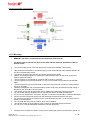
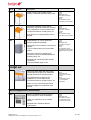
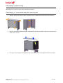
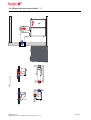
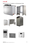
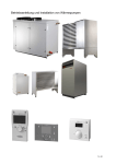
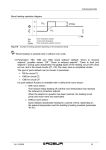
Operating instructions and installation of heat pumps Hotjet Hotjet CZ s.r.o. ! ! ! ! Operating instructions and installation of heat pumps Hotjet (3.08/2010/01) 1 z 46 Contents: 1.User instructions! 3 1.1.General information! 3 1.1.1.System description!............................................................................................................................................................................................3 1.1.2.Warning!.............................................................................................................................................................................................................4 1.2.Routine maintenance ! 5 1.3.Disposal! 5 2.Installation Instructions! 6 2.1.Handling refrigerant ! 6 2.2.Parts of heat pump! 7 2.2.1.Parts of heat pumps Hotjet “ i “!.........................................................................................................................................................................7 2.2.2.Parts of heat pumps Hotjet “ w “!........................................................................................................................................................................8 2.2.3.Parts of heat pumps Hotjet “ ask “!.....................................................................................................................................................................9 2.3.Location and connection! 10 2.3.1.Transport and storage!.....................................................................................................................................................................................10 2.3.2.Space for installation model!............................................................................................................................................................................12 2.3.3.Base and pedestal for "ASK" and external unit "s"!.........................................................................................................................................12 2.3.4.Model , base and pedestal!..............................................................................................................................................................................13 2.3.5.Rules for placement of heating valves at outdoor unit ASK:!...........................................................................................................................14 2.4.Connecting the power supply:! 15 2.4.1.Hotjet w - variation with displacement and RZ2 & RZ3!...................................................................................................................................17 2.4.2.Hotjet w - variant without body!........................................................................................................................................................................17 2.4.3.Hotjet s -indoor unit!.........................................................................................................................................................................................18 2.4.4.Hotjet s - connection with the internal unit!.......................................................................................................................................................18 3.Technical data of heat pumps Hotjet ! 19 3.1.Technical data of heat pump Hotjet “ i “! 19 3.1.1.Basic information!.............................................................................................................................................................................................19 3.1.2.Advantages!.....................................................................................................................................................................................................19 3.1.3.Installation position!..........................................................................................................................................................................................19 3.1.4.Characteristics!................................................................................................................................................................................................19 3.1.5.Technical data!.................................................................................................................................................................................................21 3.1.6.Drawing heat pump Hotjet “ i “!........................................................................................................................................................................23 3.2.Technical data of heat pump Hotjet “ ask “! 25 3.2.1.Basic information!.............................................................................................................................................................................................25 3.2.2.Advantages!.....................................................................................................................................................................................................25 3.2.3.Installation position!..........................................................................................................................................................................................25 3.2.4.Characteristics!................................................................................................................................................................................................25 3.2.5.Technical data!.................................................................................................................................................................................................27 3.2.6.Drawing heat pump Hotjet “ ASK “ké údaje HotjTechnické údaje Hotjet s!......................................................................................................29 3.3.Technical data of heat pump Hotjet “ s “! 31 3.3.1.Basic information!.............................................................................................................................................................................................31 3.3.2.Advantages:!....................................................................................................................................................................................................31 3.3.3.Installation position!..........................................................................................................................................................................................31 3.3.4.Characteristics!................................................................................................................................................................................................31 3.3.5.Technical data!.................................................................................................................................................................................................33 3.3.6.Drawing Hotjet "S" - indoor unit!.......................................................................................................................................................................37 3.3.7.Drawing Hotjet "S" - outdoor unit!.....................................................................................................................................................................38 3.4.Technical data of heat pump Hotjet “ w “! 39 3.4.1.Basic information!.............................................................................................................................................................................................39 3.4.2.Advantages!.....................................................................................................................................................................................................39 3.4.3.Installation position!..........................................................................................................................................................................................39 3.4.4.Characteristics!................................................................................................................................................................................................39 3.4.5.Technical data!.................................................................................................................................................................................................41 3.4.6.Installation Hotjet “W”!......................................................................................................................................................................................43 4.EC declaration of conformity to the heat pump! 45 5.GUARANTEE CERTIFICATE FOR THE HEAT PUMP! 46 Hotjet CZ s.r.o. ! ! 2 z 46 ! ! Operating instructions and installation of heat pumps Hotjet (3.08/2010/01) 1. User instructions 1.1. General information Congratulations on your purchase of heat pump Hotjet. Get familiar with these instructions to get the best use and a long service from the pump. The heat pump is a compact unit designed for heating water for hot service water and for heating. The source of heat is the external air, of which heat is transferred to water in an exchanger. The heat pump is a long service life and a very safe product. We wish you a trouble-free operation and a lot of thermal comfort.. 1.1.1.System description The Hotjet heat pumps are compact units designed for outdoor and indoor installation. The series Hotjet i units are intended for indoor installation in an object, and the series Hotjet e units are an alternative for external installation out of the object. These models take the energy from the air, and that is why it is not necessary to bore holes or to install ground collectors. The series Hotjet w are intended for the ground-water or water-water systems. The heat source is a borehole, a ground collector or a technological or waste heat. The heat pump is equipped with the Siemens RVS41 or RVS61 regulators. The regulators controls the running of the actual heat pump, heating of the hot service water, charging of the storage reservoir, controlling the three-stage bivalent source, directional and heating radiators circuits, swimming pool water heating and many other parts of the heating and cooling system. The regulators algorithms are practically identical, and differ only by the number of inputs, therefore the number of simultaneously connected and regulated subsystems. Each series RSV regulator is extensible by 3 input and 3 output module. Up to two AVS75 modules can be connected to one RVS. It is possible to interconnect up to 16 heat pumps of various models and outputs into the so called cascade and in this way increase the total output capacity of the installation. At the same time, the stage regulation becomes also available. Hotjet CZ s.r.o. ! ! ! ! Operating instructions and installation of heat pumps Hotjet (3.08/2010/01) 3 z 46 Principle of operation of heat pumps: 1.1.2. Warning BEWARE: The device contains electrical components under tension. The device may be opened only by a person with relevant electrical qualification. Risk of electric shock. ! The power supply circuit of the heat pump must comply with standard ČSN 33 2000 ! We recommend installation of an 30mA tripping current earth leakage relay (ČSN EN 60335-2-40 ed.) and a lockable main switch. ! The device must be connected only to properly earthed power supply. ! Before connecting equipment or removing any panel always switch off the power supply and exercise maximum caution. ! The heat pump is not intended for operation with a frequency converter. ! The heat pump must never be switched on if it is not connected to the heating circuit filled with water. ! The heat pump must never be switched on with the covers removed or when the safety features are out of operation. ! Arbitrary manipulation with connected heating system, heat pump and electrical power supply is dangerous and can lead to serious injuries. ! The device service may be performed only by qualified and authorised service personnel. ! Do not tamper with the equipment and do not interfere with its assembly arrangement. !Do not use any equipment if it has been dropped, or has been mechanically or otherwise damaged. ! Never cover the heat pump, the air inlet and discharge must be always free and open. ! Do not place the outdoor heat pump version inside enclosed premises – it will cool down and its efficiency will be affected. ! Do not install the heat pump in position, which can be flooded. ! The device should not be installed in close proximity of flammable liquids and fumes. ! Do not store or handle flammable substances neat the equipment. ! Piping and the compressor contain cooling mixture under high pressure, and therefore should not Hotjet CZ s.r.o. ! ! ! ! Operating instructions and installation of heat pumps Hotjet (3.08/2010/01) 4 z 46 be exposed to high temperatures and the danger of perforation. ! Hot water above 52° C temperature may cause serious burns or death by scalding. ! Never remove or cover any of the markings, labels and warnings placed on the heat pump, as these should be visible at all times. Replace the damaged ones with new ones. ! The control panel must be out of reach of children. ! Be careful to avoid injuries on sharper edges and projections. ! Implementation of any technical changes on the equipment is possible only with the prior written consent of HOTJET CZ s.r.o. 1.2. Routine maintenance Proper maintenance is very important to optimise the operation and to ensure long service life of the heat pump. The following points should serve as general instructions; always consult your installation company for specific maintenance requirements. The evaporator should be cleaned at least twice per year and each time when it is visibly fouled. Fouled evaporator lowers the efficiency of the operation. The external surfaces of the heat pump may be washed with a sponge and a warm soap water. Do not use bleach, abrasives or solvents, which could damage the surface of the device. The detergent should not contain acids, soda or chlorides. Make sure that the parts with electrical installation are protected against ingress of water. !! Check regularly the outdoor unit at below zero temperatures if there isn’t an excessive built up of frost or ice under the pump. Snowing or strong wind can cause obstruction or snowbound closure of the evaporator inlets. Icing and snow must be removed. Filters: The heating circuit of the pump is fitted with filters, which can be clogged. Check these at last twice a year. Close the nearest valves before and after the filter and remove the sieve. After installation deaerate the heating system and fill up the water in the heating circuit. ATTENTION: The heat pump air-water contains a fan, which can be revolving. Before maintenance of the evaporator part of the heat pump always disconnect the power supply and wait until all moving parts of the fan come to standstill! Water draining at shut-down: If the outdoor heat pump is out of operation for a longer period or if it is disconnected from the power supply, drain the water out of the unit to prevent its freezing with the disconnected power supply. The indoor unit placed inside premises free of the danger of frost does not have to be drained . Warning: The water being discharged from the heat pump could be hot, beware of the danger of scalding. ATTENTION: If the heat pump does not start or if it does not heat, consult the situation with your installation company. The heat pump cover should be removed only by a qualified worker. The following should be checked by a competent service technician: Electrical installation: Check the connection and the condition of the electrical Heating system: The functioning of the heating system must be checked prior to the heating season. 1.3. Disposal Disposal facility to a professional company specialized in the field of refrigeration or contact the manufacturer. The product contains a filling (refrigerant oil), which must be disposed of properly. Hotjet CZ s.r.o. ! ! ! ! Operating instructions and installation of heat pumps Hotjet (3.08/2010/01) 5 z 46 2. Installation Instructions This part of the documentation is intended for qualified installation and service staff as an assistant for proper installation, operation and maintenance of the heat pump HOTJET. Read it carefully, failure to comply with instructions may lead to malfunctioning of the heat pump, damage to property, scalding or electrocution injuries. 2.1. Handling refrigerant • Heat pump refrigeration circuit includes Hotjet filled with refrigerant. • Interventions in the cold circuit can only company with the appropriate qualifications. (Business license: installation, repair and reconstruction of refrigeration and heat pumps) • Refrigerant, the heat pump which has been delivered, it is stated on the label: for example, R404A, R407C, R134a. • Complete safety data sheets according to the refrigerant needs to ask [email protected]. SAFETY WARNING • The most serious adverse effects on human health when using the substance / preparation: Refrigerant vapors are heavier than air, can cause oxygen displacement. Rapid evaporation of liquid may cause frostbite. • First aid instructions: General advice: return the affected person to fresh air, keep calm and warm. Call a doctor.Breathing, perform artificial respiration. Inhalation: Go to fresh air, apply artificial respiration or oxygen. Skin contact: take off all contaminated clothing, wash with plenty of lukewarm water. Eye Contact: Rinse with plenty of water for about 15 minutes, Consult with your doctor. Ingestion is not considered a likely route of exposure. More information: Do not administer adrenaline or its derivatives. Handling and Storage: Handling: Use only in well ventilated areas. Do not breathe. Ensure adequate ventilation, smoke. Protection: Eyes -> Glasses, Hands -> insulating gloves. Hotjet CZ s.r.o. ! ! ! ! Operating instructions and installation of heat pumps Hotjet (3.08/2010/01) 6 z 46 2.2. Parts of heat pump 2.2.1.Parts of heat pumps Hotjet “ i “ Front View & Back View Position Description Position Description 1 Heating water Flow 14 Transporting holes 2 Heating water return 15 Noise suppressor 3 Soft-starter Danfoss 16 Evaporator 4 Heat pump controller 17 Radial fan 5 Switch board 18 Sandwich isolation 6 Cable bushings 19 Air exhaust 7 Condensate drainpipe 20 Suck air 8 Spring-loaded base unit of cooling circuit on silent blocks 21 Refrigerant separator Hotjet CZ s.r.o. ! ! ! ! Operating instructions and installation of heat pumps Hotjet (3.08/2010/01) 7 z 46 Position Description Position 9 Compressor 22 Description Pallet exchanger 10 Expansion valve 23 Darin Valve 11 Heating of condenser plate 24 Heat exchanger 12 Condenser plate 25 Filter dryer 13 Supporting base unit 26 Fan frame 2.2.2.Parts of heat pumps Hotjet “ w “ Front and back view 1 2 3 4 5 6 18 17 7 16 8 9 15 10 14 11 13 12 20 Position 19 Position Description 1 Inlet of the primary circuit 13 Compressor 2 Output from the heat pump primary circuit 14 Penetrations for electrical installations from the left side 3 Entry into the heating water heat pump 15 Filter Dehydrators Description Hotjet CZ s.r.o. ! ! ! ! Operating instructions and installation of heat pumps Hotjet (3.08/2010/01) 8 z 46 Position Position Description Description 4 Entry heating water heat pump 16 Sight 5 Foldable cover wiring 17 Expansion valve 6 Heat pump controller 18 Expansion valve 7 Heat exchanger 19 Refrigerant separator 8 Evaporator 20 Drain valves 9 High pressure controls and low pressure 21 1st isolation 10 Filling valves on the intake of compressor displacement 22 2nd isolation 11 Penetrations for electrical installations from the right side 23 Cover face 12 Spring-loaded base unit of cooling circuit on silent blocks 24 Plate exchanger 2.2.3.Parts of heat pumps Hotjet “ ask “ Hotjet CZ s.r.o. ! ! ! ! Operating instructions and installation of heat pumps Hotjet (3.08/2010/01) 9 z 46 Position Description Position Description 1 Isloation 11 Heat exchanger 2 Fan Cover 12 Sight 3 Fan 13 Flow switch 4 Fan frame 14 Expansion valve 5 Refrigerant separator 15 Electric box 6 Spring-loaded base unit of cooling circuit on silent blocks 16 Evaporator 7 Compressor 17 Filter dryer 8 Legs 18 Fan palte 9 Filling valves on the intake of compressor displacement 19 Plate exchanger 10 High pressure controls and low pressure 2.3. Location and connection 2.3.1.Transport and storage For the transport of heat pump is placed on a pallet. The heat pump should never be stored or installed on the side. Maximum angle of tilt in any direction is 45 degrees. It is recommended to transport in an upright position. Carriage on its side would like a written agreement. If transportation is an unavoidable side, it is necessary to leave the device in an upright position at least 24 hours before starting. Failure to follow these instructions may result in damage to the heat pump. After taking heat pump equipment unpack, remove the panel cover and check to avoid damage during shipping. Identified damage fails transport companies and ask for their review, a copy of messages you send to HOTJET CZ, s.r.o Dimensional drawings of the transport package heat pumps . 32+/('$ 32+/('& '02'(/ % $ $ & % % 32+/('% $ 3ROĀ & 1i]HYNRPSRQHQWX 6SRMRYDFtGHVND[[ .U\FtGĢHYďQQiGHVND[[ 'ĢHYR $6. 'ĢHYR $6. -PpQR 3OLVND 7\SGRNXPHQWDFH 6HULRYiYìURED 3RGSLV 'DWXP ! ! Operating instructions and installation of heat pumps Hotjet (3.08/2010/01) 2GVWUDQLWRWĢHS\D ]NRVLWRVWUpKUDQ\ 1HQLPďĢtWNRYìNUHVX +PRWQRVW & 5HYL]H 1i]HYYìNUHVX 6(67$9$Ô3/1É'ġ(9Ď11e3$/(7< 52=0e5PP[PP 3527ÿDç$6. .RQWU ! $6. 'ĢHYďQQìKUDQRO[[ .UHVOLO Hotjet CZ s.r.o. ! ÿtVORYìNUHVX 'ĢHYR )LUPD 1RUPD +27-(7VUR ' 3RĀ NXVĪ 0DWHULiO ÿtVORYìNUHVX +PRWQRVW 0ďĢtWNR $6. $ /LVW 10 z 46 32+/('& % 32+/('$ '02'(/ $ $ % & % $ 32+/('% 3ROĀ & 1i]HYNRPSRQHQWX .U\FtGĢHYďQQiGHVND[[ 'ĢHYR $6. 'ĢHYR $6. 7\SGRNXPHQWDFH 2GVWUDQLWRWĢHS\D ]NRVLWRVWUpKUDQ\ 6HULRYiYìURED 'DWXP 3RGSLV -PpQR 3OLVND 1HQLPďĢtWNRYìNUHVX +PRWQRVW & 5HYL]H 1i]HYYìNUHVX 6(67$9$Ô3/1É'ġ(9Ď11e3$/(7< 52=0e5PP[PP 3527ÿDçL .RQWU L 'ĢHYďQQìKUDQRO[[ .UHVOLO ÿtVORYìNUHVX 'ĢHYR )LUPD 1RUPD +27-(7VUR ' 3RĀ NXVĪ 6SRMRYDFtGHVND[[ 0DWHULiO ÿtVORYìNUHVX +PRWQRVW 0ďĢtWNR L $ /LVW 32+/('$ '02'(/ % 32+/('& $ $ & % 32+/('% % $ 3ROĀ & 1i]HYNRPSRQHQWX 6SRMRYDFtGHVND[[ .U\FtGĢHYďQQiGHVND[[ 'ĢHYR $6. 'ĢHYR $6. -PpQR 3OLVND 7\SGRNXPHQWDFH 6HULRYiYìURED 3RGSLV 'DWXP ! ! Operating instructions and installation of heat pumps Hotjet (3.08/2010/01) 2GVWUDQLWRWĢHS\D ]NRVLWRVWUpKUDQ\ 1HQLPďĢtWNRYìNUHVX +PRWQRVW & 5HYL]H 1i]HYYìNUHVX 6(67$9$Ô3/1É'ġ(9Ď11e3$/(7< 52=0e5PP[PP[PP 3527ÿDç:6/D7ÿDçD6 .RQWU ! $6. 'ĢHYďQQìKUDQRO[[ .UHVOLO Hotjet CZ s.r.o. ! ÿtVORYìNUHVX 'ĢHYR )LUPD 1RUPD +27-(7VUR ' 3RĀ NXVĪ 0DWHULiO ÿtVORYìNUHVX +PRWQRVW 0ďĢtWNR :6 $ /LVW 11 z 46 2.3.2.Space for installation model 300mm The heat pump is designed for installation in the house - utility rooms, cellar, garage, land, and the like. Installing the indoor unit on the construction over 50% humidity can cause condensation on the cover of the pump or air-duct. For service approach to be followed by a minimum distance diagram: Connected Heating System 600mm Electrical outlets Service access 300mm • 2.3.3.Base and pedestal for "ASK" and external unit "s" • The heat pump is equipped with side pedestals comprising adjustable legs to support the evaporator above ground in elevated position. • The heat pump can be installed on a solid base, which consists of concrete footing or paving. • The heat pump horizontal plane is set with the use of the adjustable legs. • The base material should be filled with material that drains well, e.g. crushed stone, as the condensate is discharged along the entire width of the evaporator. • It is not advisable to place the heat pumps on larger areas – e.g. parking lots, pavements - as these do not muffle noise well. Hotjet S & ASK HEAT PUMP positioning Hotjet CZ s.r.o. ! ! ! ! Operating instructions and installation of heat pumps Hotjet (3.08/2010/01) 12 z 46 2.3.4.Model , base and pedestal • Place the heat pump on a solid surface, which preferably consists of a concrete base, concrete footing or paving • It is not advisable to place the heat pumps on larger areas – e.g. parking lots, pavements - as these do not muffle noise well. • Install the heat pump at least 0,3 m above the surface. • The free space between the heat pump and the surface should be at least 0,2m high to prevent connection between the heat pump and the surface of the base in instances when ice is created. min. 0,3m min. 0,3m e model Hotjet CZ s.r.o. ! ! ! ! Operating instructions and installation of heat pumps Hotjet (3.08/2010/01) flexible hose 13 z 46 Detail of a typical heat pump connected to the heating system or the equalizing reservoir. Position Description 1 Heat pump 2 Expansion tank 7 Flexible hose 6 Flow electric boiler PV Safety valve KK Ball valve Inlet Air suck Outlet Air Exhaust 2.3.5.Rules for placement of heating valves at outdoor unit ASK: Component Position Safety valve Inside the building Drain Valve At the lowest point between HP and the inner part of the installation Ball valves Inside the building Filter The object inside the pipe towards the heat pump Petcock valve The highest point of connection inside or outside Pipe insulation Exterior of at least 20 mm, we recommend synthetic rubber Hotjet CZ s.r.o. ! ! ! ! Operating instructions and installation of heat pumps Hotjet (3.08/2010/01) 14 z 46 2.4. Connecting the power supply: The heat pump is available in these designs and regulating the location of wiring: Code Item Description Hotjet i - RZ1 RZ1 Internal electronics installation. Place for the management of the heat pump.There is no room for placement AVS37, therefore suitable for combination with QAA78. RVS41 AVS37 cable AVS-RVS Compressor contractor fan relay 3f terminal Circuit breaker control All electronics and controller in an external cabinet. The front panel space to accommodate AVS37. RVS41 AVS37 cable AVS-RVS Compressor contactor fan relay 3f terminal switch Circuit breaker control Compressor circuit breaker Switchboard wiring system 3m The rack is a space for installing the contractors and circuit breakers bivalence, auxiliary relay, etc. Supplied with connecting cable harness with connectors, the standard length of 3m. Hotjet ask RZ1 RZ1 Outdoor electronics unit has always been outsourced. Supplied with connecting cable harness connectors standard 5m. RVS41 AVS37 cablet AVS-RVS Compressor contactor fan relay 3f terminal switch Circuit breaker control Compressor circuit breaker Switchboard wiring system 5m Heat pump Hotjet with the electronics located in the distribution of indoor unit.Between indoor and outdoor unit must be carried out according to the interconnection scheme. Cable not included. RVS41 AVS37 cablet AVS-RVS Compressor contactor terminal switch Circuit breaker control Compressor circuit breaker Heat pump earth water is the internal electronics of a standard switchboard. RVS41 AVS37 cablet AVS-RVS Compressor contactor terminal Circuit breaker control Hotjet s RZS Hotjet w Without Place for the management of the heat pump. There is no room for placement AVS37, therefore suitable for combination with QAA78. Hotjet CZ s.r.o. ! ! ! ! Operating instructions and installation of heat pumps Hotjet (3.08/2010/01) 15 z 46 Code Item Description RZ2 Option-country body of water for the location of electrical panel and AVS37 HP. RVS41 AVS37 cablet AVS-RVS Compressor contactor terminal switch Circuit breaker control Compressor circuit breaker RZ3 Combined installation of the internal distribution boards and extension of space for the installation of circuit breakers and contactors bivalence, auxiliary relay, etc. RVS41 AVS37 cablet AVS-RVS compressor contactor terminal switch Circuit breaker control Compressor circuit breaker If the panel is not required AVS37 hole is blinded. RZ1 Implementation of country water and electric equipment externally. RZ1 All electronics and controller in an external cabinet. The front panel space to accommodate AVS37. The rack is a space for installing the contactors and circuit breakers bivalence, auxiliary relays, etc. RVS41 AVS37 cablet AVS-RVS Compressor contactor terminal switch Circuit breaker control Compressor circuit breaker Switchboard wiring system 3m Supplied with connecting cable harness connectors with the standard length of 3m. Hotjet w2 Without Heat pump earth water with high power (33W model and higher) has a standard internal electronics in the switchboard. The switchboard is a space for the installation of circuit breakers and contactors bivalence, auxiliary relays, etc. RVS61 AVS37 cablet AVS-RVS 2 compressor contactor terminal switch Circuit breaker control 2 x circuit breaker Compressor There is no room for placement AVS37, therefore suitable for combination with QAA78. Self-supplied controller RZ0 Delivery of electrical components and control equipment without installation. Option for installation into an existing cabinet. RVS41 AVS37 cablet AVS-RVS Compressor contactor Circuit breaker control 3 meters wiring system Supplied with a standard cable tie and diagram. Hotjet CZ s.r.o. ! ! ! ! Operating instructions and installation of heat pumps Hotjet (3.08/2010/01) 16 z 46 2.4.1.Hotjet w - variation with displacement and RZ2 & RZ3 • Dismount the front plate • Loosen the locking screw flip cover from the underside of the lid carrier • Pull the cover • 400V power cable ready to install WAGO terminals. 2.4.2. Hotjet w - variant without body After removal of the front cover, remove the cover plate Switchboard 400V power cable ready to install WAGO terminals. Hotjet CZ s.r.o. ! ! ! ! Operating instructions and installation of heat pumps Hotjet (3.08/2010/01) 17 z 46 2.4.3. Hotjet s -indoor unit Dismantling and connect the power cord is the same as Hotjet w 2.4.4. Hotjet s - connection with the internal unit Unscrew the top cover with 4 screws, 2 screws from the front side and 2 screws at the rear, as shown Remove the lid and the side cover plate U-shaped lift up, because the bottom of the "sit" on the pins at the bottom of the machine. The upper part is located in the distribution wire connection terminal. See diagram electrical schematics. Hotjet CZ s.r.o. ! ! ! ! Operating instructions and installation of heat pumps Hotjet (3.08/2010/01) 18 z 46 3. Technical data of heat pumps Hotjet 3.1. Technical data of heat pump Hotjet “ i “ • The condensate drainpipe can be carried out into sewerage Source of heat: suction air Installation position garage, cellar, workroom, utility room, farm building Characteristics External part of installation: there is none, just holes in the wall and covering grate/shutter on the facade New generation of heat pumps hotjet “i” is highly functional while the price is still unbeatable. How did we achieve this? By optimization of the design, careful choice and serial production. Basic information • • • • • • • • • • • It is adjusted for installation into a building Source of heat is the energy of external air It works up to -20°C It is designed for unmanned water heating up to do 55°C. It is suitable for floor and radiator systems Regulation maintains heating of domestic hot water (DHW) Compact construction does not require much space 2 levels of regulation with a possibility of extension Wired and wireless control Effective anti-corrosion protection Wide range of accessories Advantages • • • • • • • • The heat pump is not exposed to the outdoor environment (water, snow) Heat dissipations stay in the house The heat which accumulates in the cellar can be partially used (air exhaust dehumidifies the cellar) It is possible to extract heat from the foul air from recuperation/ventilation It is possible to preheat the source air by a solar system Noise of the unit is suppressed by a wall Aerodynamic noise is muffled by air conduits It does not “provoke” thieves Hotjet CZ s.r.o. ! ! ! ! Operating instructions and installation of heat pumps Hotjet (3.08/2010/01) Noise suppression: • Compressor scroll without mechanically movable pistons and valves • Multiple spring-loaded housing of compressor and cooling circuit • Solid compact baseplate • Multiply insulation against noise on the covers • Insulated air-conditioning pipeline • Optional installation of circular silencer (part of an airconditioning pipeline) Space required: the heat pump takes up the area of 0.7m2. Upper cover height is 900mm. Coupling airconditioning sleeves take up approximately 50mm. Defrosting: dynamically, according to need, by hot gases Condensate drain: by a hose into the drainage or by a condensate pump Control units: AVS37 (standard) • Operator panel in a switchboard • Without spatial temperature reading (solved by external thermostat) QAA78 wireless unit (optional) Combined spatial and operating device Advantages of QAA78: • Heat pump, heating system and heating of DHW may be controlled from any place in the house. • Spatial thermostat function informs the regulator of temperature in the place where the unit is placed. • • Support of connection to the heating system: Connection without surge tank, directly to the heating system Connection with a surge tank point-to-point, four-point Support for surge tanks with floating boiler • Surge tank (storage reservoir): Is not necessary (requires consideration) • 19 z 46 • • May be charged equithermally May be charged, so-called, forcedly, when it is charged up to the required temperature. Startup of this function may be linked to switching electrical energy rates, certain time or it can be controlled by external command. One of the advantages is the possibility of “collection” of heat when the conditions are better. For example the air temperature is higher. Divalent source: • Support of electric cartridges in the flow or reservoir • Support of external sources (current gas, electric and other boilers) • Three-stage or one-stage bivalence control Heating system: • Solely equithermal control (according to the outdoor temperature only) • Control according to the spatial temperature • Equithermal control with a linkage to space (room) • One regulator can maintain 2 mixing heating circuits and one pump circuit • Each heating circuit may be controlled absolutely independently by its spatial unit • It is possible to use current thermostats with ON/OFF regime • It is possible to add more heating circuits by using zone regulators RVS • Integration with superior regulators is possible, e.g. heating circuits control in particular rooms . • Heating of DHW (domestic hot water) • Tank heating by an individual boiler • Tank heating by a floating boiler in a surge tank • Internal exchanger or external exchanger for boilers without internal exchanger or if the size is insufficient • Flow heating • Forced heating • Combination with solar heating • Control of electric body in boiler or external source for DHW heating • Function for heat re-pumping between the surge tank and boiler (typically, when the tank is heated from the solid fuel boiler, by warm-water fireplace insert) Solar system: • More than 50 ways of integration • Definition of 3 types of take-off 3 (DHW, surge tank, pool) • Integration with heat pump (heat pump serves as a second source for DHW) • • • • • Support of heating and cooling on pipe-in-pipe and four-pipe distribution systems Support of alternating cooling and heating of DHW or pool Support of passive cooling with regard to ground water system Dew point check Dehumidifier control Cascade: • Even the standard regulation supports integration of 16 heat pumps or other sources into cascade • Different types of sources are supported in the cascade (gas boilers, electric boilers, solid fuel boilers) • Gas boilers with regulation Siemens may be connected into the cascade with our heat pumps. On the Czech market, these are brands such as Geminox, Brötje, Baxi and Viadrus equipped with LMU units. Further functions: • HDO input (blocking of electric heating) • Input of external requirement for the heat 0-10V, regime switching, heat pump start-up INSTALLATION: Installation is easy. Every skilled heating engineer with an electrician should be able to install the heat pump. However, with regard to installation we prefer our trained partners who also carry out the heat pump startup. Possibly, you may order service of authorized heat pump startup via our commercial section. Not enough space? This should not be a problem with our company. Narrow passageway? Cranked staircase? Hotjet "i" may be delivered dismantled and it may be assembled at the place of installation. For such installation it is necessary to invite a cooling circuit specialist who has the proper equipment. If you are not sure whether the heat pump fit into the place of installation, you can use a model of the heat pump in the size 1:1. Should you have any other questions, do not hesitate to contact us. Do you have a low ceiling? It definitely is not a problem with us. The heat pump height is 902mm. Pool heating: • is supported Fireplace insert: • If the tank is charged from fireplace, the heat pump is turned off • Function for overheated tank cooling • In combination with another RVS, it is possible to control the circulatory pump of the fireplace or solid fuel boilers directly, including other functions, such as monitoring of source extinction. Cooling: Hotjet CZ s.r.o. ! ! ! ! Operating instructions and installation of heat pumps Hotjet (3.08/2010/01) 20 z 46 3.1.1.Technical data MODEL HOTJET 8i Performance data HOTJET 11i HOTJET 15i Power output / Power input / COP A7/W35 7,8 / 2,04 / 3,8 9.3 / 2.45 / 3.8 10.8 / 2.79 / 3.8 A2/W35 7,2 / 2,01 / 3,6 8.6 / 2.39 / 3.6 10.1 / 2.76 / 3.6 A7/W45 7,4 / 2,46 / 3,0 8.8 / 2.93 / 3.0 10.3 / 3.39 / 3.0 A2/W45 6,6 / 2,46 / 2,7 8.0 / 2.96 / 3.0 9.3 / 3.44 / 2.7 Technical data Temperature operating limits for air Temperature limit of heating system Heating and reversing water communication pipe Heating water flow rate Head loss, heating side Protection against freezing water heating Air flow rate -20 °C to 35 °C +15 to +55°C (below outdoor temperature -10°C max. output temperature 50°C) 3/4’’ 1.3 m³/h 1.5 m³/h 1.8 m³/h <20kPa yes 2 200 m³/h 2 200 m³/h Air channel diameter 2 200 m³/h 400mm Refrigerant circuit Refrigerant Refrigerant quantity ( Kg ) Defrosting R407C R404A R407C 2.1 2.3 2.4 Automatic, according to the need. Upon request (manual) Way of defrosting By hot coolant (reversal) Heating of the condensate bulk tank Condensate drainage yes By a hose Cut-off pressure of lowpressure pressurestat Cut-off pressure of highpressure pressurestat Technical information, weight 0.08 MPa 2.8 MPa Dimensions (W x D x H) 1040 x 632 x 902 mm Weight 210 kg 210 kg 215 kg Designed for internal installation (there are holes on the walls for air suction and air outlet) Placement Anti-corrosive protection Powder coat,, galvanized sheet, cataphoresis Color RAL 7036 Model i : IP40 Degree of protection ( EN 60 529 ) Electrical connection 3/N/PE ~400 V, 50 Hz Power supply - 3 phases 400V / 3 / 50Hz Compressor Copeland scroll Service current [A] 4.5 5 5.8 Starting current [A] 18 20 23 Maximum service current [A] 6.5 7 8.8 Compressor protection [A] 16B 16B 16B Compressor supply line (n x mm2) 5x1.5 Hotjet CZ s.r.o. ! ! ! ! Operating instructions and installation of heat pumps Hotjet (3.08/2010/01) 21 z 46 MODEL HOTJET 8i HOTJET 11i HOTJET 15i 1/N/PE ~230 V, 50 Hz Electrical connection Power supply - 1 phase 230V / 1 / 50 Hz Compressor Copeland scroll Service current [A] Starting current [A] Maximum service current [A] Compressor protection [A] 15 A 15A 914 A 61 A 84 A 84A 20 A 20 A 20 A 25 B 32 B 32B Compressor supply line (n x mm2) Noise level 3x4 Sound power Lw [dB(A)] < 50 Sound pressure Lp [dB(A)] < 37 Equipment Control electronics Siemens RVS41 Operator panel AVS37 on the device Wireless device QAA78 yes (optionally RVS61) yes optional External switchboard with electronics Soft start unit optional (the whole wiring system is housed in external switchboard) optionally Danfoss Condensate pump optional Integration into cascade Up to 16 heat pumps or mixed sources are supported Bivalence (back-up power supply) External tubular electric boiler optionally (three-stage 2.5 5 7.5kW) Electric cartridges in storage reservoir External gas or electric boiler supported supported Electric post heating of boiler supported Solid fuel boiler supported discharge of storage reservoir if it is overheated *) Values as A2/W35 mean: intake air temperature is 2 ° C, outlet water temperature from the heat pump is 35 ° C. Values are reported according to standards EN 14511-1 to 4:2005 " " " " " Hotjet CZ s.r.o. ! ! ! ! " Operating instructions and installation of heat pumps Hotjet (3.08/2010/01) 22 z 46 E E E směr přístupu k elektru a chladícímu okruhu E E 3.1.2.Drawing heat pump Hotjet “ i “ Hotjet CZ s.r.o. ! ! ! ! Operating instructions and installation of heat pumps Hotjet (3.08/2010/01) 23 z 46 Hotjet CZ s.r.o. ! Operating instructions and installation of heat pumps Hotjet (3.08/2010/01) ! ! ! 24 z 46 ' & % $ 95$71É27231É92'$ 91Ď-äÌ=É9,7 .RQWURO .UHVOLO )LUPD 3OLVND -PpQR +27-(7VUR 967831Ì27231É92'$ 91Ď-äÌ=É9,7 3RGSLV 2'92'.21'(1=É78 'DWXP +PRWQRVW 0DWHULiO 6e5,29É9ë52%$ 7\SGRNXPHQWDFH 2GVWUDQLWRWĢHS\D RVWUpKUDQ\ 6$&Ì+5'/2 5HYL]H 9ë)8.29e+5'/2 0ďĢtWNR ÿtVORYìNUHVX /LVW $6,1 $ 6(67$9$7ÿ9='8&+92'$91,ġ1Ì 3529('(1ÌL 1i]HYYìNUHVX 1HQLYìNUHVRYpPďĢtWNR & % $ 3.2. Technical data of heat pump Hotjet “ ask “ Characteristics Heat source: air Noise suppression: Use of scroll compressor design eliminates traditional pistons and valves Compressor and cooling circuit multiple spring suspension Solid and compact foundation slab Multiple layer noise-proof insulation on covers Low speed, 630mm large diameter serrated blades fan The latest range of the air-to-water compact design heat pumps for external installation feature advanced design and high heating factor at affordable price. Basic information Compact dimensions Air is the source of heat Intended for attendance-free water heating up to 55°C. Suitable for floor and radiator heating systems Compressor cooling support Hot water for space heating and service hot water supply central control by means of supplied regulation system Choice from two regulators and an option for further extension Wired or wireless control Stainless steel, unpainted finish Wide range of accessories Ideal for new objects without internal spaces. State-of-the-art technology with a front-end electronics for affordable price. Installation position Intended for outdoor installation next to a building structure or on its roof Hotjet CZ s.r.o. ! ! ! ! Operating instructions and installation of heat pumps Hotjet (3.08/2010/01) QAA78 advantages: the heat pump and the hot water for space heating and service hot water supply can be controlled from anywhere in the house/building space thermostat function, informs the regulator of the local unit’s temperature status Heating system connection support / alternatives: direct connection to the heating system without using a storage reservoir Two or four-point connection to the storage reservoir Storage reservoir support by means of a floating boiler Advantages Control units: AVS37 (standard) control panel in switchboard without space temperature sensing (resolved with the use of an external thermostat) QAA78 wireless unit (optional) combined space and service device Storage reservoir (accumulation tank): not required (subject to evaluation) equithermal charging availability availability of so-called forced charging, when the required temperature is reached through charging. The function’s initiation can be linked to time or command controlled switching between electricity tariffs. The advantage is the possibility of heat “collection” during favourable weather conditions, e.g. during higher air temperatures. Bivalent source: electrical cartridges support in the flow or in the reservoir External sources support (existing gas, electricity and other energy driven boilers) Three or single-stage bivalent controlز 25 z 46 Heating system: Purely equithermal control (by the external temperature only) control according to space temperature Equithermal coupled with space control One regulator manages up to two mixing heat circuits and one pump circuit Each heating circuits can be controlled fully independently with the use of its own space unit The existing ON/OFF switching mode thermostats can be used Addition of more heating circuits with the use of zone regulators RVS Integration with a higher level regulators, e.g. individual rooms temperature control through separate heating circuits can be achieved Hot service water heating Reservoir heating with an independent boiler Storage reservoir heating with the use of floating boiler Internal or external boiler heat exchangers without internal exchanger or in case of inadequate size flow heating forced heating combined with solar heating Hot service water heating external source or boiler electrical heating element adjustment function of heat transfer between the storage reservoir and the boiler (a typical case when the reservoir heating is supplied by a solid fuel boiler or a fireplace water heating insert) is supported • • • • Fireplace water heating insert: the heat pump is switched off when the reservoir • is supplied by the fireplace water heating insert Overheated reservoir cool-down function • • A fireplace or solid fuel boiler circulating pump can be directly controlled in combination with RVS63, including other functions such as monitoring of burning intensity to prevent a fire going out. • • Cooling: • cooling support • heating as well as cooling support in two-pipe and fourpipe distribution systems • support of interchangeable cooling and hot service water heating or swimming pool heating • dew-point check • dehumidifier control Cascade: The standard regulation supports connecting of up to 16 heat pumps or other sources is available already at the standard regulation level Various type of sources are supported in a cascade (gas, electrical and solid fuel boilers) Gas boilers with Siemens regulation can be cascade connected with our heat pumps. On the Czech market this applies to the trade marks Geminox, Brötje, Baxi and Viadrus, equipped with the LMU units. Solar system: over 50 connecting methods definition of 3 take-offs (hot service water, storage reservoir, swimming pool) integration with a heat pump (hp functions as a second hot service water) Swimming pool heating: Hotjet CZ s.r.o. ! ! ! ! Operating instructions and installation of heat pumps Hotjet (3.08/2010/01) Additional functions: Centralised ripple control input (blocking electrical heating) External 0-10V heat requirement input, mode changeover switching, heat pump start…. 26 z 46 3.2.1. Technical data MODEL Performance data A7/W35 A2/W35 A7/W45 A2/W45 Technical data 8ask 11ask 8,8 / 2,0 / 4,4 7,6 / 2,0 / 3,8 8,4 / 2,4 / 3,5 7,4 / 2,4 / 3,1 11,4 / 2,6 / 4,4 9,9 / 2,6 / 3,8 11,3 / 3,2 / 3,5 9,9 / 3,2 / 3,1 15ask 18ask 21ask Power output / Power input / COP Temperature operating limits for air Temperature limit of heating system Heating and reversing water communication pipe Heating water flow rate Pressure loss Protection against freezing water heating Air flow rate Refrigerant circuit Refrigerant type Refrigerant quantity ( Kg ) Defrosting Type of defrosting Cut-off pressure of lowpressure pressurestat Cut-off pressure of highpressure pressurestat Technical information, weight Dimensions (W x D x H) Weight Installation site Cabinet Degree of protection ( EN 60 529 ) Electrical connection Nominal voltage 3 phases Type of compressor Nominal current ( A ) Starting current ( A ) Maximum current ( A ) Fusing [A] Compressor supply line (n x mm2) Electrical connection Nominal voltage 1 phase Type of compressor Nominal current ( A ) Starting current ( A ) Maximum current ( A ) Fusing [A] with soft-strater Compressor supply line (n x mm2) Hotjet CZ s.r.o. ! ! ! ! 13,2 / 3,0 / 4,4 11,5 / 3,0 / 3,8 13,0 / 3,7 / 3,5 11,4 / 3,7 / 3,1 16,2 / 3,7 / 4,4 14,1 / 3,7 / 3,8 15,8 / 4,5 / 3,5 13,9 / 4,5 / 3,1 18,4 / 4,2 / 4,4 16,0 / 4,2 / 3,8 18,3 / 5,2 / 3,5 16,0 / 5,2 / 3,1 2,6 m³/h 3 m³/h -20 °C to 35 °C +15 to +55°C 1’’ 1,3 m³/h 1,5 m³/h 1,8 m³/h <20kPa Yes 3 000 m³/h 4 500 m³/h R404A 2.6 2.8 2.8 2.9 2.9 155 160 Automatic Cycle reversal 0.08 MPa 2.8 MPa 145 145 1296x503x1137 mm 150 Outside Stainless steel IP43 3/N/PE ~400 V, 50 Hz 4.5 18 6.5 16B 5 20 7 16B 5x1.5 400V / 3 / 50Hz Copeland scroll 5.8 23 8.8 16B 9 36 12.8 20B 9.1 36.4 13.1 20B 5x2.5 1/N/PE ~230 V, 50 Hz 230V / 1 / 50 Hz Copeland scroll 9,5 A 61 A 20 A 25 B 48A Operating instructions and installation of heat pumps Hotjet (3.08/2010/01) 914 A 84 A 20 A 32 B 67 A 3x4 914 A 84A 20 A 32B 67 A No No No No No No No No 5x2,5 27 z 46 MODEL 8ask Noise level Sound power level dB(A) 11ask 15ask 18ask 21ask 61 57 Sound pressure level at 1 m dB(A) Equipment Control electronics Siemens RVS41 Operator panel AVS37 on the device Wireless device QAA78 External switchboard with electronics Soft start unit Condensate pump yes (optionally RVS61) yes optional optional (the whole wiring system is housed in external switchboard) optionally Danfoss optional *) Values as A2/W35 mean: intake air temperature is 2 ° C, outlet water temperature from the heat pump is 35 ° C. Values are reported according to standards EN 14511-1 to 4:2005 Hotjet CZ s.r.o. ! ! ! ! Operating instructions and installation of heat pumps Hotjet (3.08/2010/01) 28 z 46 Výkonové diagramy tepelných čerpadel řady ASK pro topnou vodu 35°C 23 Topný výkon [kW] Elektrický příkon (kW] 22 21ask 20 18ask 18 16 15ask 14 11ask 12 8ask 10 8 6 21ask 18ask 15ask 11ask 8ask 4 2 0 -22 -20 -18 -16 -14 -12 -10 -8 -6 -4 -2 0 2 4 6 8 10 12 14 16 18 21 Teplota nasávaného vzduchu [°C] Výkonové diagramy tepelných čerpadel řady ASK pro topnou vodu 45°C 23 Topný výkon [kW] Elektrický příkon (kW] 21ask 22 20 18ask 18 16 15ask 14 11ask 12 8ask 10 8 6 21ask 18ask 15ask 11ask 8ask 4 2 0 -22 -20 -18 -16 -14 -12 -10 -8 -6 -4 -2 0 2 4 6 8 10 12 14 16 18 Teplota nasávaného vzduchu [°C] 3.2.2.Drawing heat pump Hotjet “ ASK “ Hotjet CZ s.r.o. ! ! ! ! Operating instructions and installation of heat pumps Hotjet (3.08/2010/01) 29 z 46 21 ké údaje HotjTechnické údaje Hotjet s Operating instructions and installation of heat pumps Hotjet (3.08/2010/01) ! ! ! ' & % $ 32+/('' 3ġ,32-29$&Ì91Ď-äÌ=É9,7 32+/('& 32+/('% 6752-1ÌÿÉ67 9ë)8.29É675$1$ /$0(/29ë9ë'8&+=9ë3$51Ì.8 32+/('$ .RQWURO .UHVOLO 3OLVND -PpQR +27-(7VUR )LUPD 3RGSLV 'DWXP +PRWQRVW 0DWHULiO 6pULRYiYìURED 7\SGRNXPHQWDFH 967837231e92'< 9ë67837231e92'< 3ġ,32-29$&Ì91Ď-äÌ=É9,7 2GVWUDQLWRWĢHS\D RVWUpKUDQ\ ÿtVORYìNUHVX 0ďĢtWNR 5HYL]H 32+/('& 32+/('$ 32+/('' /LVW $6. 52=0Ď529É6(67$9$ 7ÿ$6. 91(5(=29e03529('(1Ì 1HQLYìNUHVRYpPďĢtWNR 1i]HYYìNUHVX 32+/('% '32+/('1$7ÿ$6.= 1$6É9$&Ì675$1$ 9='8&+8'29ë3$51Ì.8 Hotjet CZ s.r.o. ! 30 z 46 $ & % $ 3.3. Technical data of heat pump Hotjet “ s “ Installation position Indoor unit: any place inside the building – technical room, basement, garage... Outdoor part of the system: ground, wall, roof Characteristics Heat source: air New models of air to water heat pumps of the split type distinguish by a favourable price with outstanding parameters. The split installation enables flexible utilisation of the heat pump in various types of buildings. Basic information Compact size with a possibility to install the indoor unit to the wall Air is used as a heat source Intended for automated water heating up to 55 °C Suitable for both floor and radiator heating systems Control system can ensure hot water heating Compact structure with minimum demands on space (top view 0,35 m2) Supports passive or compressor cooling Central heating and hot water heating control via the attached control system Selection out of 2 controllers, further extension possible Both wire and wireless control Effective anticorrosive protection Wide range of accessories Soundproofing: Scroll compressor without mechanically travelling pistons and valves Several springing levels of compressor mounting and cooling circuit Robust compact base slab Several layers of noise insulation on covers Low-speed fan with large diameter of 630 mm and saw blades for noise elimination Required space: Heat pump takes up the area of 0,35 m2 Height of the upper lid is approximately 1 m Passage of 60 cm is sufficient for heat pump installation Control units: AVS37 (standard) control panel in the switchgear no space temperature sensors (external thermostat delivered) QAA78 wireless unit (option) combined space and control device Advantages of QAA78 unit: heat pump, heating system and hot water heating can be controlled from any place in the building Space thermostat function – thermostat informs the controller about the temperature of the area where the unit is placed Advantages: “Hot” part of the system is placed inside the building Higher heating factor Noise split to 2 places High-performance soundproofing of the indoor unit Outdoor unit equipped with low-speed fan with large diameter of 630 mm and saw blades for noise elimination No impact of the climatic conditions Advanced technology with sophisticated electronics for favourable price Hotjet CZ s.r.o. ! ! ! ! Operating instructions and installation of heat pumps Hotjet (3.08/2010/01) Connection to Heating System Connection without a surge tank, directly to the heating system Two- point or four-point connection with a surge tank Support for floating boiler reservoirs Surge tank (storage tank): not necessary (to be assessed) can be equithermally charged can be force-charged, i. e. charged to the required 31 z 46 temperature. Start-up of the function can be related to the power supply tariffs switch-over, either via time or external command. The advantage consists in a possibility to accumulate heat under better conditions, i. e. when the air temperature is higher. Bivalent source: Supports electrical cartridges in flow or tank Supports exernal sources (existing gas, electrical or other boilers) Three-level or single-level bivalence control Heating system: Solely equithermal control (acc. to the ambient temperature only) If combined with another RVS, the wood stove or solid fuel boiler circulation pumps can be controlled directly, including other functions, e. g. source extinction monitoring. Cooling: Supports both passive and compressor cooling Supports heating and cooling in the both two-pipe and four-pipe networks Supports alternating cooling and heating of hot water or swimming pool Supports passive cooling at ground to water systems Dew point check Dehumidifier control Space temperature control Equithermal control in relation to space One controller can control up to 2 heating circuits and one pump circuit Each heating circuit can be controlled independently via its own space unit Existing thermostats with ON/OFF modes can be used More heating circuits can be added via the RVS zone controllers Possible integration with master controllers, i. e. control Cascade: Standard control supports connection up to 16 heat pumps or other sources in the cascade mode Various types of sources are supported in the cascade (gas, electrical or fuel solid boilers) Gas boilers with Siemens control can be connected with our heat pumps to the cascade. The following brands are available on the Czech market: Geminox, Brötje, Baxi and Viadrus, equipped with the LMU units. of heating circuits per room Other functions: Entry of ripple control (electrical heating blocking) Entry of external command on heat 0 – 10 V, mode switching, heat pump start-up... Hot water heating Water heated in the tank with a separate boiler Water heated in the surge tank with a floating boiler Internal exchanger or external exchanger for boilers without an internal exchanger or with insufficient capacity Flow heating Force heating Combination with solar heating Control of electrical heater in the boiler or external source for hot water heating Function of heat transfer between the surge tank and boiler (typical situation: the tank is heated by the solid fuel boiler or hot water wood stove) Solar system: Over 50 ways of connection Definition of 3 off-takes (hot water heating, surge tank, swimming pool) Integration with the heat pump (can meanwhile work as a secondary source for hot water heating) Swimming pool heating: Supported Wood stove: In case the tank is heated from the stove, the heat pump is off Function of overheated tank cooling Hotjet CZ s.r.o. ! ! ! ! Operating instructions and installation of heat pumps Hotjet (3.08/2010/01) 32 z 46 3.3.1. Technical data MODEL Performance data A7/W35 A2/W35 A7/W45 A2/W45 Technical data Temperature operating limits for air 8s 11s 15s 8,8 / 2,0 / 4,4 11,4 / 2,6 / 4,4 13,2 / 3,0 / 4,4 16,2 / 3,7 / 4,4 7,6 / 2,0 / 3,8 9,9 / 2,6 / 3,8 11,5 / 3,0 / 3,8 14,1 / 3,7 / 3,8 8,4 / 2,4 / 3,5 11,3 / 3,2 / 3,5 13,0 / 3,7 / 3,5 7,4 / 2,4 / 3,1 9,9 / 3,2 / 3,1 11,4 / 3,7 / 3,1 22S 35S 50S 18,4 / 4,2 / 4,4 28,8 / 6,56 / 4,4 40,7 / 9,3 / 4,4 16,0 / 4,2 / 3,8 25,1 / 6,57 / 3,8 35,4 / 9,3 / 3,8 15,8 / 4,5 / 3,5 18,3 / 5,2 / 3,5 27,2 / 7,7 / 3,5 38,9 / 11,1 / 3,5 13,9 / 4,5 / 3,1 16,0 / 5,2 / 3,1 23,8 / 7,7 / 3,1 34,1 / 11,1 / 3,1 Power output / Power input / COP -20 až +30 Temperature limit of heating system Heating and reversing water communication pipe Air flow rate Fan diameter (mm) Heating water flow rate Pressure loss of heating Party Protection against freezing water heating Refrigerant circuit 18s 12 až 60°C R407C 6 - 55°C R404A 1” 3000 m³/h 1.3 m³/h 2” 3000 m³/h 3000 m³/h 4500 m³/h 650 ( Ziehl Abegg ) 1.5 m³/h 1.8 m³/h 2.6 m³/h 4500 m³/h 2 x 4500 m³/h 3 x 4500 m³/h 2 x 650 3 x 650 3 m³/h 4.2 m³/h < 20kPa 7.2 m³/h < 30kPa Yes Refrigerant type Cut-off pressure of low-pressure pressurestat Cut-off pressure of high-pressure pressurestat Technical information, weight Dimensions (W x D x H) Indoor unit Number of evaporators Dimensions (W x D x H) outdoor unit weight of the refrigerator 110 compartment [kg] external evaporator mass (Kg) R407C / R404A 0,08 MPa 2,8 MPa 1300 x 525 x 998 mm 635 x 525 x 998 mm 1 2 3 185 205 190 285 20 30 1296x503x1137 110 115 120 125 90 Installation Split system Corrosion protection inside the unit Powder coat, galvanized, cataphoresis Color RAL 7036 Anticorrosive protection of the outdoor unit stainless steel, unvarnished Sheets Degree of protection (EN 60 529 ) IP 43 Electrical connection 3/N/PE ~400 V, 50 Hz Power supply 400V / 3 / 50Hz Compressor Copeland scroll Maximum service current [A] 6.5 Hotjet CZ s.r.o. ! ! ! ! 7 Operating instructions and installation of heat pumps Hotjet (3.08/2010/01) 8.8 12.8 13.1 33 z 46 MODEL 8s 11s 15s 18s 22S 35S 50S Starting current [A] 18 20 23 36 36.4 55 80 16B 16B 16B 20B 20B 32A char B 40A char C 5x1,5 5x1,5 5x1,5 5x1,5 5x2,5 5x4 5x10 Compressor protection [A] Compressor supply line (n x mm2) Noise level Sound power Lw [dB (A)] Sound pressure Lp [dB(A)] < 50 < 60 < 40 < 50 Equipment Control electronics Siemens RVS41 Operator panel AVS37 on the device Wireless device QAA78 External switchboard with electronics Soft start unit Condensate pump Integration into cascade Bivalence (back-up power supply) External tubular electric boiler Electric cartridges in storage reservoir External gas or electric boiler Electric post heating of boiler yes, (optionally RVS61) yes, Optional Optional (the whole wiring system is housed in external switchboard) optionally Danfoss Optional Up to 16 heat pumps or mixed sources are supported Optionally (three-stage 2.5 5 7.5kW) Supported Supported Supported Solid fuel boiler Supported discharge of storage reservoir if it is overheated Hotjet CZ s.r.o. ! ! ! ! Operating instructions and installation of heat pumps Hotjet (3.08/2010/01) 34 z 46 Výkonové diagramy tepelných čerpadel řady "Hotjet s" pro topnou vodu 35°C 22 Topný výkon [kW] Elektrický příkon (kW] 23 21s 22 18s 20 18 16 15s 14 11s 12 8s 10 8 6 21s 18s 15s 11s 8s 4 2 0 -22 -20 -18 -16 -14 -12 -10 -8 -6 -4 -2 0 2 4 Teplota nasávaného vzduchu [°C] 6 8 10 12 14 16 18 21 Výkonové diagramy tepelných čerpadel řady "Hotjet s" pro topnou vodu 45°C 23 Topný výkon [kW] Elektrický příkon (kW] 22 21s 20 18s 18 16 15s 14 11s 12 8s 10 8 6 21s 18s 15s 11s 8s 4 2 0 -22 -20 -18 -16 -14 -12 -10 -8 -6 -4 -2 0 2 4 6 8 10 12 14 16 18 Teplota nasávaného vzduchu [°C] Hotjet CZ s.r.o. ! ! ! ! Operating instructions and installation of heat pumps Hotjet (3.08/2010/01) 35 z 46 21 Výkonové diagramy tepelných čerpadel řady "Hotjet s" pro topnou vodu 35°C 50 50s 48 Topný výkon [kW] Elektrický příkon (kW] 46 44 42 40 38 35s 36 34 32 30 28 26 24 22 20 18 16 14 12 10 50s 8 35s 6 4 0 -22 -20 -18 -16 -14 -12 -10 -8 -6 -4 -2 0 2 4 6 8 10 12 14 16 18 21 Teplota nasávaného vzduchu [°C] Výkonové diagramy tepelných čerpadel řady "Hotjet s" pro topnou vodu 45°C 50 Topný výkon [kW] Elektrický příkon (kW] 50s 48 46 44 42 40 38 35s 36 34 32 30 28 26 24 22 20 18 16 14 12 50s 10 35s 8 6 4 0 -22 -20 -18 -16 -14 -12 -10 -8 -6 -4 -2 0 2 4 6 8 10 12 14 16 18 Teplota nasávaného vzduchu [°C] Hotjet CZ s.r.o. ! ! ! ! Operating instructions and installation of heat pumps Hotjet (3.08/2010/01) 36 z 46 21 3.3.2.Drawing Hotjet "S" - indoor unit ! ! ! % $ Operating instructions and installation of heat pumps Hotjet (3.08/2010/01) ' & 9678335292',ÿ(2'29/É'É1Ì $.2081,.$&( 02æ1267/(9e+21(%2 35$9e+23ġ,32-(1Ì92',ÿÔ 9678335292',ÿ(6,/29e (1(5*,( Hotjet CZ s.r.o. ! 37 z 46 )LUPD .RQWU .UHVOLO 3OLVND -PpQR +27-(7VUR 3RGLV 'DWXP +PRWQRVW 0DWHULiO PP 2GVWUDQLWRWĢHS\D RVWUpKUDQ\ 9ìNUHVEH]PďĢtWND 5HYL]H 0ďĢtWNR ÿtVORYìNUHVX /LVW 6 $ & % $ 52=0Ď529É6(67$9$7ÿ6 352(;7(51Ì9ë3$51Ì.63,7 1i]HYYìNUHVX 9678327231e92'<'27ÿ 9ë678327231e92'<=7ÿ 9ë6783.$3$/1e+2&+/$',9$=7ÿ'29ë3$51Ì.863/,7 967833/<11e+2&+/$',9$=9ë3$51Ì.863/,7'27ÿ PP 7\SYìNUHVX 3É-(&Ì+5'/21$WU 3É-(&Ì+5'/21$&8WU 3ġ,32-29$&Ì91Ď-äÌ=É9,7-V 3ġ,32-29$&Ì91Ď-äÌ=É9,7-V ! ! ! Operating instructions and installation of heat pumps Hotjet (3.08/2010/01) D C B D 1 857 1107 1241 1271 2 STAVĚCÍ NOŽKA REKTIFIKACE +-20 mm 3 Kontrol. Kreslil Jméno Pliska 1273 1296 POHLED Z HORA Podpis 22.5.09 Datum Hmotnost: 13.67 Materiál: Sériová v"roba Typ dokumentace: V!PARNÍK Odstranit otřepy a ostré hrany 5 Měřítko: Číslo v"kresu: List: C B A A4 SPLIT v"parník 00813 S ROZMĚROVÁ SESTAVA Název v"kresu: MATERIÁL: NEREZOV! PLECH Revize: V!STUP PLYN. CHLADIVA CU trubka průměr 22mm 173 103 VSTUP KAPAL. CHLADIVA CU trubka průměr 16mm 435 500 6 STAVĚCÍ NOŽKA +- 20 mm POHLED Z PRAVA Neni v"kresové měřítko AXIÁLNÍ VENTILÁTOR POHLED ZE SPODU 4 DETAIL D MĚŘÍTKO 1 : 10 HOTJET s.r.o Firma: POHLED ZE STRANY NASÁVÁNÍ OCHRANNÁ MŘÍŽKA POHLED ZE STRANY V!FUKU 2 503 Hotjet CZ s.r.o. ! 196,45 A 1 3.3.3. Drawing Hotjet "S" - outdoor unit 38 z 46 3.4. Technical data of heat pump Hotjet “ w “ • High technology with top electronics at reasonable price. Installation position Source of heat: ground collector, borehole, well, service water Place of installation: anywhere inside a building – utility room, cellar, garage… External part of installation: primary source – borehole, ground collector, wells Characteristics New models of heat pumps ground – water and water – water bring along completely new construction of the box, cooling circuit and control electronics. In a simplified way we can say that there is nothing left from the original model. Basic information • Compact size with a possibility of installation towards the wall. • Source of heat is a ground collector, borehole or well. • It is designed for unmanned water heating up to 55°C. • It is suitable for floor and radiator systems • Regulation maintains heating of domestic hot water (DHW) • Compact construction does not require much space (it takes up 0.35m2) • Support of passive or compressor cooling • Central control of heating and DHW heating through supplied regulation • Choice out of 2 regulators with a possiblility of further extension • Wired and wireless control • Effecitve anti-corrosion protection • Wide range of accessories Advantages • In comparison to air – water system: • More stable power output • Higher heating factor • No aerodynamic noise • It is not influenced by weather conditions Hotjet CZ s.r.o. ! ! ! ! Operating instructions and installation of heat pumps Hotjet (3.08/2010/01) Noise suppression: • Compressor scroll without mechanically movable pistons and valves • Multiple spring-loaded housing of compressor and cooling circuit • Solid compact baseplate • Multiply insulation against noise on the covers Space required: the heat pump takes up the area of 0.35m2. Upper cover height is approximately 1m. Passageway of 60cm is fully sufficient for the installation. Control units: AVS37 (standard) • Operator panel in a switchboard • Without spatial temperature reading (solved by external thermostat) QAA78 wireless unit (optional) Combined spatial and operating device Advantages of QAA78: • Heat pump, heating system and heating of DHW may be controlled from any place in the house. • Spatial thermostat function informs the regulator of temperature in the place where the unit is placed. Support of connection to the heating system: • Connection without surge tank, directly to the heating system • Connection with a surge tank point-to-point, four-point • Support for surge tanks with floating boiler Surge tank (storage reservoir): • Is not necessary (requires consideration) • May be charged equithermally • May be charged, so-called, forcedly, when it is charged up to the required temperature. Startup of this function may be linked to switching electrical energy rates, certain time or it can be controlled by external command. One of the advantages is the possibility of “collection” of heat when the conditions are better. For example the air temperature is higher. 39 z 46 Divalent source: • Support of electric cartridges in the flow or reservoir • Support of external sources (current gas, electric and other boilers) • Three-stage or one-stage divalence control Heating system: • Solely equithermal control (according to the outdoor temperature only) • Control according to the spatial temperature • Equithermal control with a linkage to space (room) • One regulator can maintain 2 mixing heating circuits and one pump circuit • Each heating circuit may be controlled absolutely independently by its spatial unit • It is possible to use current thermostats with ON/OFF regime • It is possible to add more heating circuits by using zone regulators RVS • Integration with superior regulators is possible, e.g. heating circuits control in particular rooms Heating of DHW (domestic hot water) • Tank heating by an individual boiler • Tank heating by a floating boiler in a surge tank • Internal exchanger or external exchanger for boilers without internal exchanger or if the size is insufficient • Flow heating • forced heating • combination with solar heating • control of electric body in boiler or external source for DHW heating • function for heat repumping between the surge tank and boiler (typically, when the tank is heated from the solid fuel boiler, by warm-water fireplace insert) Cascade: • Even the standard regulation supports integration of 16 heat pumps or other sources into cascade • Different types of sources are supported in the cascade (gas boilers, electric boilers, solid fuel boilers) • Gas boilers with regulation Siemens may be connected into the cascade with our heat pumps. On the Czech market, these are brands such as Geminox, Brötje, Baxi and Viadrus equipped with LMU units. Further functions: • HDO input (blocking of electric heating) • Input of external requirement for the heat 0-10V, regime switching, heat pump startup INSTALLATION: Installation is easy. Every skilled heating engineer with an electrician should be able to install the heat pump. However, with regard to installation we prefer our trained partners who also carry out the heat pump startup. Possibly, you may order service of authorized heat pump startup via our commercial section. Solar system: • more than 50 ways of integration • definition of 3 types of take-off 3 (DHW, surge tank, pool) • integration with heat pump (heat pump serves as a second source for DHW) Pool heating: • is supported Fireplace insert: • If the tank is charged from fireplace, the heat pump is turned off • Function for overheated tank cooling • In combination with another RVS, it is possible to control the circulatory pump of the fireplace or solid fuel boilers directly, including other functions, such as monitoring of source extinction. Cooling: • Support of passive and compressor cooling • Support of heating and cooling on pipe-in-pipe and four-pipe distribution systems • Support of alternating cooling and heating of DHW or pool • Support of passive cooling with regard to ground water system • Dew point check • Dehumidifier control Hotjet CZ s.r.o. ! ! ! ! Operating instructions and installation of heat pumps Hotjet (3.08/2010/01) 40 z 46 3.4.1. Technical data MODEL Output data Heat output / input / Heating factor B0/W35 B0/W45 W10/W35 W10/W45 Land area – wet soil Sub-circuits each 100m Technical data Temperature limit of primary side Temperature limit of heating system Heating and reversing water communication pipe Volume rate of flow, primary side (m3/h) Water passage through the heating circuit (m3/h) Head loss, heating side Head loss, primary side Protection of heating water against freezeup Refrigerant circuit Refrigerant Cut-off pressure of low-pressure pressurestat Cut-off pressure of high-pressure pressurestat Technical information, weight width x depth x height [mm] weight (kg) Installation Anti-corrosive protection Colour Degree of protection (EN 60 529 ) Electrical data 400 V Power supply Compressor Service current [A] Starting current [A] Maximum service current [A] Compressor protection [A] Compressor supply line (n x mm2) Noise level 9W 12W 16W 20W 33W 50W 7,5 / 1,63 / 4,6 7,1 / 2,05 / 3,5 10,4 / 2,26 / 4,6 10,0 / 2,89 / 3,5 16,0 / 3,48 / 4,6 15,0 / 5,33 / 3,5 19,2 / 4,17 / 4,6 18,1 / 5,23 / 3,5 32,0 / 6,96 / 4,6 30,2 / 8,73 / 3,5 44,62 / 10,05 / 4,44 10,4 / 1,62 / 6,4 9,8 / 2,03 / 4,8 330 4 14,7 / 2,29 / 6,4 13,8 / 2,86 / 4,8 470 6 22,3 / 3,48 / 6,4 20,9 / 4,33 / 4,8 680 8 26,3 / 4,10 / 6,4 24,5 / 5,07 / 4,8 810 10 44,0 / 6,86 / 6,4 41,0 / 8,49 / 4,8 1370 17 60,04 / 10,54 / 5,7 58,5 / 12,95 / 4,5 1920 24 -10 to +30 +15 to +55°C 1” (3/4") 2” 1,1 1,8 2,6 3,0 4,4 7.9 1,0 1,6 2,3 2,7 4,2 7.2 < 20kPa < 30kPa < 25kPa < 35kPa yes R407C / R134A 0,08 MPa 2,8 MPa 630 x 580 x 1080 103 103 630 x 580 x 1080 1042 x 635 x 863 112,5 114 115 internal komaxit, galvanized sheet, cataphoresis 267 RAL 7036 IP 24 4,5 18 6,5 5,8 23 8,8 9 36 12,8 16B 16B 20B 5x1,5 Sound power Lw [dB (A)] Sound pressure Lp [dB(A)] Hotjet CZ s.r.o. ! ! ! ! 400V / 3 / 50Hz Copeland scroll 9,1 38 13,1 20B 5x2,5 17,9 55 20,4 25 80 27 32B 40B 5x6 < 50 < 60 < 40 < 50 Operating instructions and installation of heat pumps Hotjet (3.08/2010/01) 41 z 46 MODEL Equipment 9W 12W 16W 20W 33W 50W Control electronics Siemens RVS41 (optionally RVS61) Phase monitoring order, phase loss and phase imbalance (RVS41 externally, RVS61 internally) Operator panel yes AVS37 on the device Wireless device optional QAA78 External switchboard Optional (the whole wiring system is housed in external switchboard) with electronics Soft start unit optionally Danfoss (Siemens) Integration into Up to 16 heat pumps or mixed sources are supported cascade Bivalence (back-up power supply) External tubular Hotjet optionally (three-stage 2,5 - 5 - 7,5kW) other power outputs are customelectric boiler made Electric cartridges in supported storage reservoir External gas or supported electric boiler Electric post heating of boiler Solid fuel boiler supported supported discharge of storage reservoir if it is overheated *) Values as A2/W35 mean: intake air temperature is 2 ° C, outlet water temperature from the heat pump is 35 ° C. Values are reported according to standards EN 14511-1 to 4:2005. " " " " " Hotjet CZ s.r.o. ! ! ! ! " Operating instructions and installation of heat pumps Hotjet (3.08/2010/01) 42 z 46 3.4.2.Installation Hotjet “W” Hotjet CZ s.r.o. ! ! ! ! Operating instructions and installation of heat pumps Hotjet (3.08/2010/01) 43 z 46 Hotjet CZ s.r.o. ! ! ! ! Operating instructions and installation of heat pumps Hotjet (3.08/2010/01) 44 z 46 4. EC declaration of conformity to the heat pump Manufacturer: HOTJET CZ s.r.o. M.Kopeckého 675 708 00 Ostrava-Poruba Czech Republic http://www.hotjet.eu Hereby confirm that the design and construction of the product(s) listed below, in the version(s) placed on the market by us, conform to the relevant requirements of the applicable EC directives. This declaration becomes invalidated if any modifications are made to the product(s) without our prior authorization. Designation of the product(s): Air-to-water heat pumps for indoor installation Type: Hotjet 8i, Hotjet 11i , Hotjet 15i, Hotjet 18i, Hotjet 21i Air-to-water heat pumps for outdoor installation Type: Hotjet 8ask, Hotjet 11ask , Hotjet 15ask, Hotjet 18ask, Hotjet 21ask Air-to-water heat pumps for split system Type: Hotjet 8s, Hotjet 11s , Hotjet 15s, Hotjet 18s, Hotjet 22s ,Hotjet 35s, Hotjet 50s. Brine-to-water, water-to-water heat pumps for indoor installation Type: Hotjet 9w, Hotjet 12w , Hotjet 16w, Hotjet 20w, Hotjet 33w ,Hotjet 55w. EC Directives: EC Low Voltage Directive (73/23/EEC) EC EMC Directive (89/336/EEC) is in compliance with the requirements of a Government Regulation No. 9 / 2002, 17/2003, 18/2003 163/2002 and 312/2005, as amended, is compatible with the following codes and standards: • • • • • • • EN 60 335-2-40:2002 EN 60 335-1:2001 EN 55014-1:2000 + A1: 2001 + A2: 2002 EN 55014-2:1997 + A1: 2001 EN 61000-3-2:2000 EN 61000-3-3:1995 + A1: 2001 EN 14511-1 to 4:2005 Authorized Body 211: TÜV CZ s.r.o Novodvorská 994, 142 21 Prague 4, CR, IC: 63987121, which issued a protocol for assessment of conformity with the technical specifications of the type of personnel costs. No: 636/70/09/BT/ AO/B dated March 7, 2009. Manufacturer confirms that the characteristics of the product meet the essential requirements of regulation, standards and regulations above and the product is under conditions of intended use and safe measures are taken to ensure conformity with the technical documentation and the basic requirements. Technical Director Ostrava , 07.07.2009 ing. Richard Köhle Hotjet CZ s.r.o. ! ! ! ! Operating instructions and installation of heat pumps Hotjet (3.08/2010/01) 45 z 46 5. GUARANTEE CERTIFICATE FOR THE HEAT PUMP Type (model) designa2on: .......................................................................................... Compressor serial number: .......................................................................................... Date of sale: .......................................................................................... Date set into opera2on: .......................................................................................... Name and address of supplier: .......................................................................................... ............................................. Signature and stamp of supplier *) Guarantee period: 24 months from se6ng into opera8on, no later however than 26 months from the date of sale. *) Guarantee period: 60 months from se6ng into opera8on, no later however than 26 months from the date of sale. Danfoss SoB Starter serial number: .............................................. HOTJET CZ s.r.o. declares that it has adopted such measures to ensure the conformity of all products launched onto the market with the technical documenta2on. Condi8ons for acknowledgement of the guarantee – joint condi8ons for 24 and 60 months: 1. The operator ensures electrical connec2on in line with the valid norms 2. The pump is installed and set into opera2on by an installa2on (coopera2ng) company in line with the manufacturer’s technical condi2on, the installa2on instruc2ons and the instruc2ons in the documenta2on or those stated on the product. 3. The product is not be used for any other purpose than the one it is designed for. 4. No modifica2ons are performed on the equipment by an unauthorised party. Condi8ons for extension of the guarantee to 60 months: 1. A Danfoss SoQ Starter is included in the delivery when purchasing the heat pump. 2. The 60-‐month guarantee is provided as follows: 24 months for everything and 36 months for parts. 3. A flat fee of 30 Euro will be charged for each call-‐out to perform guarantee service in the period 24-‐60 months. The customer orders inspec2on by a Hotjet technician aQer the second and fourth hea2ng season. This must be no later than as at 30.8. of the year in ques2on using the contact details stated below. 4. The price for the service inspec2on is set at a flat rate of 100 Euro . 5. Performance of the extended guarantee relates to parts in the heat pump located inside its cover and the RVS regulator in the external switchboard. The guarantee relates to material defects, func4onal defects or defects created during manufacture. The guarantee does not relate to defects created by an incorrect project, faulty installa4on, handling, storage, connec4on or incorrect opera4on, inappropriate electrical protec4on and installa4on, non-‐adherence to the prescribed electric voltage, unqualified or inappropriate interven4on and handling, modifica4on or demoun4ng (in the event of subsequent installa4on, a condi4on for reten4on of the rights from the guarantee is comple4on of all records rela4ng to installa4on), inappropriate use, natural disaster, Acts of God, violent damage and failure to perform maintenance. The guarantee shall also expire in the event of interference with the product by an unauthorised party. Regular wear and tear of opera4ng media is not subject of the guarantee. Opera4ng media are not the subject of the guarantee. Only goods supplied by HOTJET CZ s.r.o. are the subject of the guarantee. Liability for choice of the product and use shall be borne in full by the buyer. The product must be used in the manner and for the purpose which it is designed for. The installa4on company provides a guarantee corresponding to the guarantee period provided for the delivery of the equipment. Customer: …………………………………………………………………………………………………………… …………………………………………………………………………………………………………… The team at HOTJET CZ s.r.o. * www.hotjet.cz * wish you the greatest of sa2sfac2on when using our products In the event of any technical defects, please contact the installa2on company. This guarantee cer2ficate is required for handling claims. Please send service request together with a copy of this cer2ficate to: [email protected], fax: +420 596 639 693 HOTJET CZ s.r.o. is registered with the Regional Court in Ostrava, Sec2on C, Insert 41279 *) Select by checking off the appropriate length of guarantee provided by Hotjet CZ s.r.o for the heat pump Amounts stated do not include VAT, which will be added in line with the valid rate at the 8me of performance! Hotjet CZ s.r.o. ! ! ! ! Operating instructions and installation of heat pumps Hotjet (3.08/2010/01) 46 z 46