1
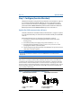
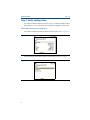
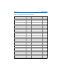
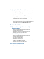
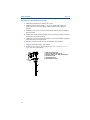
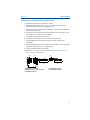
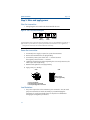
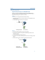
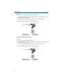
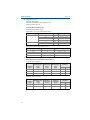
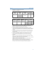
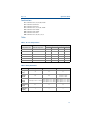
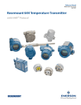
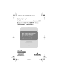
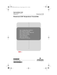
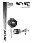
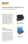
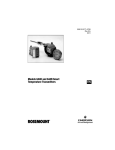
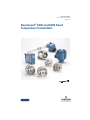
Quick Start Guide 00825-0100-4728, Rev BD May 2014 Rosemount® 644H and 644R Smart Temperature Transmitters Quick Start Guide May 2014 NOTICE This installation guide provides basic guidelines for the Rosemount 644. It does not provide instructions for detailed configuration, diagnostics, maintenance, service, troubleshooting, or installation. Refer to the 644 Reference Manual (document number 00809-0100-4728) for more instruction. The manual and this QSG are also available electronically on www.rosemount.com. Explosions could result in death or serious injury. Installation of this transmitter in an explosive environment must be in accordance with the appropriate local, national, and international standards, codes, and practices. Please review the Product Certifications for any restrictions associated with a safe installation. In an Explosion-Proof/Flame-Proof installation, do not remove the transmitter covers when power is applied to the unit. Process leaks may cause harm or result in death. Install and tighten thermowells or sensors before applying pressure. Do not remove the thermowell while in operation. Electrical shock can result in death or serious injury. Avoid contact with the leads and terminals. High voltage that may be present on leads can cause electrical shock. Contents Configure (bench calibration) . . . . . .page 3 Wire and apply power . . . . . . . . . . page 12 Verify configuration . . . . . . . . . . . . . . . page 4 Perform a loop test . . . . . . . . . . . . page 15 Set the switches . . . . . . . . . . . . . . . . . . page 7 Product Certifications . . . . . . . . . . page 16 Mount the transmitter . . . . . . . . . . . . page 8 2 Quick Start Guide May 2014 Step 1: Configure (bench calibration) The 644 communicates using the field communicator (communication requires a loop resistance between 250 and 1100 ohms. Do not operate when power is below 12 Vdc at the transmitter terminal). Refer to the 644 Reference Manual (document number 00809-0100-4728) and the Field Communicator Reference Manual (document number 00809-0100-4275) for more information. Update the field communicator software The field communicator Field Device Revision Dev v6, DD v1 or higher is required for complete functionality. The device will communicate with all previous 644 DD revisions. Perform the following steps to determine if an upgrade is required. 1. Connect the sensor (see the wiring diagram located on the inside of the housing cover). 2. Connect the bench power supply to the power terminals (“+” or “–”). 3. Connect a field communicator to the loop across a loop resistor or at the power/signal terminals on the transmitter. 4. The following message will appear if the communicator has a previous version of the device descriptors (DDs). NOTICE Upgrade the communicator software to access new XMTR functions. Continue with old description? Note If this notice does not appear, the latest DD is installed. If the latest version is not available, the communicator will communicate properly. But, when the transmitter is configured to utilize the advanced features of the transmitter (such as one of the added sensor input types), the user will experience trouble communicating and will be prompted to turn the communicator off. To prevent this from happening, upgrade to the latest DD or answer NO to the question and default to the generic transmitter functionality. Figure 1. Connecting a Communicator to a Bench Loop 644 Head Mount Transmitter 644 Rail Mount Transmitter A A C B D B A. 250 RL 1100 B. AMS C D C. Field communicator D. Power supply 3 Quick Start Guide May 2014 Step 2: Verify configuration The traditional interface Fast Key sequences in Table 1 and Device Dashboard Fast Key Sequences in Table 2 may be used for transmitter configuration and startup. Field communicator user interface The Traditional Interface Fast Key Sequences can be found on Table 1 on page 5. Figure 2. Traditional Interface The Device Dashboard Fast Key Sequence can be found on Table 2 on page 6. Figure 3. Device Dashboard 4 Quick Start Guide May 2014 Table 1. Traditional Interface Fast Key Sequences Function Fast Keys Function Fast Keys Active Calibrator 1, 2, 2, 1, 3 Open Sensor Holdoff 1, 3, 5, 3 Alarm/Saturation 1, 3, 3, 2 Percent Range 1, 1, 5 AO Alarm Type 1, 3, 3, 2, 1 Poll Address 1, 3, 3, 3, 1 Burst Mode 1, 3, 3, 3, 3 Process Temperature 1, 1 Burst Option 1, 3, 3, 3, 4 Process Variables 1, 1 Calibration 1, 2, 2 PV Damping 1, 3, 3, 1, 3 Callendar-Van Dusen 1, 3, 2, 1 PV Unit 1, 3, 3, 1, 4 Configuration 1, 3 Range Values 1, 3, 3, 1 D/A Trim 1, 2, 2, 2 Review 1, 4 Damping Values 1, 1, 10 Scaled D/A Trim 1, 2, 2, 3 Date 1, 3, 4, 2 Sensor Connection 1, 3, 2, 1, 1 Descriptor 1, 3, 4, 3 Sensor 1 Setup 1, 3, 2, 1, 2 Device Info 1, 3, 4 Sensor Serial Number 1, 3, 2, 1, 4 Device Output Configuration 1, 3, 3 Sensor 1 Trim 1, 2, 2, 1 Diagnostics and Service 1, 2 Sensor 1 Trim-Factory 1, 2, 2, 1, 2 Filter 50/60 Hz 1, 3, 5, 1 Sensor Type 1, 3, 2, 1, 1 Hardware Rev 1, 4, 1 Software Revision 1, 4, 1 Hart Output 1, 3, 3, 3 Status 1, 2, 1, 4 Intermittent Detect 1, 3, 5, 4 Tag 1, 3, 4, 1 LCD Display Options 1, 3, 3, 4 Terminal Temperature 1, 3, 2, 2, Loop Test 1, 2, 1, 1 Test Device 1, 2, 1 LRV (Lower Range Value) 1, 1, 6 URV (Upper Range Value) 1, 1, 7 LSL (Lower Sensor Limit) 1, 1, 8 USL (Upper Sensor Limit) 1, 1, 9 Measurement Filtering 1, 3, 5 Variable Mapping 1, 3, 1 Message 1, 3, 4, 4 Variable Re-Map 1, 3, 1, 5 Meter Configuring 1, 3, 3, 4, 1 Write Protect 1, 2, 3 Meter Decimal Point 1, 3, 3, 4, 2 2-Wire Offset 1, 3, 2, 1, 2, 1 Num Req Preams 1, 3, 3, 3, 2 5 May 2014 Quick Start Guide Input/verify Callendar Van-Dusen constants If sensor matching is being used with this combination of a transmitter and sensor, verify the constants input. 1. At the Home screen, select 1 Device Setup, 3 Configuration, 2 Sensor Config, 1 Sensor 1, 3 Cal Van-Dusen. Set the control loop to manual. Select OK. 2. Select Cal Van-Dusen at the Enter Sensor Type prompt. 3. Select the appropriate number of wires at the Enter Sensor Connection prompt. 4. Enter the Ro, Alpha, Beta, and Delta values from the stainless steel tag attached to the special-order sensor. 5. Select OK after you return the control loop to automatic control. Table 2. Device Dashboard Fast Key Sequences 6 Function Fast Keys Function Fast Keys Active Calibrator 2, 2, 4, 2 Num Req Preams 2, 2, 5, 2 Alarm/Saturation 2, 2, 2, 6 Open Sensor Holdoff 2, 2, 4, 4 Burst Mode 2, 2, 5, 3 Percent Range 2, 2, 2, 4 Burst Option 2, 2, 5, 4 Poll Address 2, 2, 5, 1 Calibration 2, 1, 2 PV Damping 2, 2, 1, 6 Callendar-Van Dusen 2, 2, 1, 10 PV Unit 2, 2, 1, 4 Configuration 2, 1, 1 Range Values 2, 2, 2, 5 D/A Trim 3, 4, 2 Scaled D/A Trim 3, 4, 3 Damping Values 2, 2, 1, 6 Sensor Connection 2, 2, 1, 3 Date 1, 7, 8 Sensor 1 Setup 2, 2, 1 Descriptor 1, 7, 6 Sensor Serial Number 2, 2, 1, 7 Device Info 1, 7 Sensor 1 Trim 3, 4, 1 Device Output Configuration 2, 2, 2 Sensor 1 Trim-Factory 3, 4, 1, 2 Filter 50/60 Hz 2, 2, 4, 7, 1 Sensor Type 2, 2, 1, 2 Hardware Rev 1, 7, 9, 3 Software Revision 1, 7, 9, 4 Hart Output 2, 2, 5 Tag 2, 2, 4, 1, 1 LCD Display Options 2, 2, 3 Terminal Temperature 3, 3, 2 Loop Test 3, 5, 1 URV (Upper Range Value) 2, 2, 2, 5, 2 LRV (Lower Range Value) 2, 2, 2, 5, 3 USL (Upper Sensor Limit) 2, 2, 1, 8 LSL (Lower Sensor Limit) 2, 2, 1, 9 Variable Mapping 2, 2, 5, 5 Message 1, 7, 7 Variable Re-Map 2, 2, 5, 5, 5 Meter Configuring 2, 2, 3, 1 Write Protect 2, 2, 4, 6 Meter Decimal Point 2, 2, 3, 2 2-Wire Offset 2, 2, 1, 5 May 2014 Quick Start Guide Input/verify Callendar Van-Dusen constants If sensor matching is being used with this combination of a transmitter and sensor, verify the constants input. 1. From the Home screen, select 2 Configure, 2 Manual Setup, 1 Sensor. Set the control loop to manual and select OK. 2. Select Cal VanDusen at the Enter Sensor Type prompt. 3. Select the appropriate number of wires at the Enter Sensor Connection prompt. 4. Enter the Ro, Alpha, Delta, and Beta values from the stainless steel tag attached to the special-order sensor when prompted. 5. Return the control loop to automatic control and select OK. 6. To disable the transmitter-sensor matching feature from the Home screen select 2 Configure, 2 Manual Setup, 1 Sensor, 10 SensorMatching-CVD. Choose the appropriate sensor type from the Enter Sensor Type prompt. Step 3: Set the switches 644H (switch on bottom right of electronics module) Without an LCD display 1. Set the loop to manual (if applicable) and disconnect the power. 2. Remove the electronics housing cover. 3. Set the switch to the desired position. Reattach housing cover. 4. Apply power and set the loop to automatic control. With an LCD display (644H only) 1. Set the loop to manual (if applicable) and disconnect the power. 2. Remove the electronics housing cover. 3. Snap-off the LCD display straight off. 4. Set the switch to the desired position. 5. Reattach the LCD display and electronics housing cover (consider LCD display orientation – rotate in 90 degree increments). 6. Apply power and set the loop to automatic control. 644R (switch on middle of front panel) 1. Open the front door of the 644R Rail Mount Transmitter 2. Set the switch to the desired position. 7 May 2014 Quick Start Guide Step 4: Mount the transmitter Mount the transmitter at a high point in the conduit run to prevent moisture from draining into the transmitter housing. Typical connection head installation Head mount transmitter with DIN plate style sensor 1. Attach the thermowell to the pipe or process container wall. Install and tighten the thermowell before applying process pressure. 2. Verify the transmitter failure mode switch. 3. Assemble the transmitter to the sensor. Push the transmitter mounting screws through the sensor mounting plate and insert the snap rings (optional) into the transmitter mounting screw groove. 4. Wire the sensor to the transmitter (see “Wire and apply power” on page 12 for more information). 5. Insert the transmitter-sensor assembly into the connection head. Thread the transmitter mounting screw into the connection head mounting holes. Assemble the extension to the connection head. Insert the assembly into the thermowell. 6. Slip the shielded cable though the cable gland. 7. Attach a cable gland into the shielded cable. 8. Insert the shielded cable leads into the connection head through the cable entry. Connect and tighten the cable gland. 9. Connect the shielded power cable leads to the transmitter power terminals. Avoid contact with sensor leads and sensor connections. 10. Install and tighten the connection head cover. Enclosure covers must be fully engaged to meet explosion-proof requirements. B A C D E A. 644H Transmitter B. Connection head C. Thermowell 8 F D. Transmitter mounting screws E. Integral mount sensor with flying leads F. Extension Quick Start Guide May 2014 Typical universal head installation Head mount transmitter with threaded sensor 1. Attach the thermowell to the pipe or process container wall. Install and tighten thermowells before applying process pressure. 2. Attach necessary extension nipples and adapters to the thermowell. Seal the nipple and adapter threads with silicone tape. 3. Screw the sensor into the thermowell. Install drain seals if required for severe environments or to satisfy code requirements. 4. Verify the transmitter failure mode switch. 5. Pull the sensor wiring leads through the universal head and transmitter. Mount the transmitter in the universal head by threading the transmitter mounting screws into the universal head mounting holes. 6. Mount the transmitter-sensor assembly into the thermowell. Seal adapter threads with silicone tape. 7. Install conduit for field wiring to the conduit entry of the universal head. Seal conduit threads with silicone tape. 8. Pull the field wiring leads through the conduit into the universal head. Attach the sensor and power leads to the transmitter. Avoid contact with other terminals. 9. Install and tighten the universal head cover. Enclosure covers must be fully engaged to meet explosion-proof requirements. A D B C E A. Threaded thermowell B. Threaded style sensor C. Standard extension D. Universal head (transmitter inside) E. Conduit entry 9 May 2014 Quick Start Guide Rail mount transmitter and sensor 1. Attach the transmitter to a suitable rail or panel. 2. Attach the thermowell to the pipe or process container wall. Install and tighten the thermowell, according to plant standards, before applying pressure. 3. Attach the sensor to the connection head and mount the entire assembly to the thermowell. 4. Attach and connect sufficient lengths of sensor lead wire from the connection head to the sensor terminal block. 5. Tighten the connection head cover. Enclosure covers must be fully engaged to meet explosion-proof requirements. 6. Run sensor lead wires from the sensor assembly to the transmitter. 7. Verify the transmitter failure mode switch. 8. Attach the sensor wires to the transmitter (see “Wire and apply power” on page 12 for more information). C A B D B E F 10 A. Rail mount transmitter B. Sensor leads with cable glands C. Integral mount sensor with terminal block D. Connection head E. Standard extension F. Threaded thermowell Quick Start Guide May 2014 Rail mount transmitter with threaded sensor 1. Attach the transmitter to a suitable rail or panel. 2. Attach the thermowell to the pipe or process container wall. Install and tighten the thermowell before applying pressure. 3. Attach necessary extension nipples and adapters. Seal the nipple and adapter threads with silicone tape. 4. Screw the sensor into the thermowell. Install drain seals if required for severe environments or to satisfy code requirements. 5. Screw the connection head to the sensor. 6. Attach the sensor lead wires to the connection head terminals. 7. Attach additional sensor lead wires from the connection head to the transmitter. 8. Attach and tighten the connection head cover. Enclosure covers must be fully engaged to meet explosion-proof requirements. 9. Set the transmitter failure mode switch. 10. Attach the sensor wires to the transmitter (see “Wire and apply power” on page 12 for more information). A B C D A. Rail mount transmitter B. Threaded sensor connection head C. Standard extension E D. Threaded style sensor E. Threaded thermowell 11 May 2014 Quick Start Guide Step 5: Wire and apply power Wire the transmitter Wiring diagrams are located inside the terminal block cover. Figure 4. Sensor Connections Diagram 1234 2-wire RTD and 1234 3-wire RTD and (2) 1234 4-wire RTD and 1234 T/C and mV(1) (1) The transmitters must be configured for at least a 3-wire RTD in order to recognize an RTD with a compensation loop. (2) Rosemount Inc. provides 4-wire sensors for all single element RTDs. Use these RTDs in 3-wire configurations by leaving the unneeded leads disconnected and insulated with electrical tape. Power the transmitter 1. An external power supply is required to operate the transmitter. 2. Remove the terminal block cover (if applicable). 3. Connect the positive power lead to the “+” terminal. Connect the negative power lead to the “–” terminal. 4. Tighten the terminal screws. When tightening the sensor and power wires, the max torque is 6 in.-lbs (0.7 N-m). 5. Reattach and tighten the cover (if applicable). 6. Apply power (12 – 42 Vdc). 644H A B 644R A 1 2 3 4 Max torque is 6 in.-lbs (0/7 N-m) C C A. Sensor terminals B. Communication terminals C. Power/Configuration terminals Load limitation 12 The power required across the transmitter power terminals is 12 to 42.4 Vdc (the power terminals are rated to 42.4 Vdc). To prevent damaging the transmitter, do not allow terminal voltage to drop below 12.0 Vdc when changing the configuration parameters. Quick Start Guide May 2014 Ground the transmitter Ungrounded thermocouple, mV, and RTD/Ohm inputs Each process installation has different requirements for grounding. Use the grounding options recommended by the facility for the specific sensor type, or begin with grounding option 1 (the most common). Option 1 1. Connect sensor wiring shield to the transmitter housing. 2. Ensure the sensor shield is electrically isolated from surrounding fixtures that may be grounded. 3. Ground signal wiring shield at the power supply end. A C B D A. Sensor wires B. Shield ground point C. Transmitter D. 4–20 mA loop Option 2 1. Connect signal wiring shield to the sensor wiring shield. 2. Ensure the two shields are tied together and electrically isolated from the transmitter housing. 3. Ground shield at the power supply end only. 4. Ensure the sensor shield is electrically isolated from the surrounding grounded fixtures. 5. Connect shields together, electrically isolated from the transmitter A C B D A. Sensor wires B. Shield ground point C. Transmitter D. 4–20 mA loop 13 May 2014 Quick Start Guide Option 3 1. Ground sensor wiring shield at the sensor, if possible. 2. Insure that the sensor wiring and signal wiring shields are electrically isolated from the transmitter housing. 3. Do not connect the signal wiring shield to the sensor wiring shield. 4. Ground signal wiring shield at the power supply end. A C B D A. Sensor wires B. Shield ground point C. Transmitter D. 4–20 mA loop Grounded thermocouple inputs Option 4 1. Ground sensor wiring shield at the sensor. 2. Ensure that the sensor wiring and signal wiring shields are electrically isolated from the transmitter housing. 3. Do not connect the signal wiring shield to the sensor wiring shield. 4. Ground signal wiring shield at the power supply end. A C B D A. Sensor wires B. Shield ground point 14 C. Transmitter D. 4–20 mA loop May 2014 Quick Start Guide Step 6: Perform a loop test The Loop Test command verifies transmitter output, loop integrity, and operation of any recorders or similar devices installed in the loop. Traditional interface Initiate a loop test 1. Connect an external ampere meter in series with the transmitter loop (so the power to the transmitter goes through the meter at some point in the loop.) 2. From the home screen select: 644H and 644R: 1 Device Setup, 2 Diag/Serv, 1 Test Device, 1 Loop Test. 3. Select a discrete milliampere level for the transmitter to output. At Choose Analog Output select 1 4mA, 2 20mA or select 3 Other to manually input a value between 4 and 20 milliamperes. 4. Select Enter to show the fixed output. 5. Select OK. 6. In the test loop, check that the transmitter’s actual mA output and the HART mA reading are the same value. If the readings do not match, either the transmitter requires an output trim or the current meter is malfunctioning. 7. After completing the test, the display returns to the loop test screen and allows the user to choose another output value. To end the Loop Test, Select 5 End and Enter. Device dashboard Initiate a loop test 1. Connect an external ampere meter in series with the transmitter loop (so the power to the transmitter goes through the meter at some point in the loop.) 2. From the home screen select: 644H and 644R: 3 Service Tools, 5 Simulate, 1 Loop Test. 3. Select a discrete milliampere level for the transmitter to output. At Choose Analog Output select 1 4mA, 2 20mA or select 3 Other to manually input a value between 4 and 20 milliamperes. 4. Select Enter to show the fixed output. 5. Select OK. 6. In the test loop, check that the transmitter’s actual mA output and the HART mA reading are the same value. If the readings do not match, either the transmitter requires an output trim or the current meter is malfunctioning. 7. After completing the test, the display returns to the loop test screen and allows the user to choose another output value. To end the Loop Test, Select 5 End and Enter. 15 Quick Start Guide May 2014 Product Certifications Approved Manufacturing Locations Rosemount Inc. - Chanhassen, Minnesota, USA Rosemount Temperature GmbH – Germany Emerson Process Management Asia Pacific – Singapore European Directive Information A copy of the EC Declaration of Conformity can be found at the end of the Quick Start Guide. The most recent revision of the EC Declaration of Conformity can be found at www.rosemount.com. Ordinary Location Certification from FM Approvals As standard, the transmitter has been examined and tested to determine that the design meets the basic electrical, mechanical, and fire protection requirements by FM Approvals, a nationally recognized test laboratory (NRTL) as accredited by the Federal Occupational Safety and Health Administration (OSHA). North America E5 FM Explosionproof, Dust-Ignitionproof Certificate: 3006278 Standards Used: FM Class 3600: 2011, FM Class 3615: 2006, FM Class 3616: 2011, FM Class 3810: 2005, NEMA-250: 250: 2003, ANSI/IEC 60529: 2004 Markings: XP CL I, DIV 1, GP B, C, D; DIP CL II / III, GP E, F, G; T5(-50 °C Ta +85 °C); Type 4X, IP66 I5 FM Intrinsic Safety and Nonincendive Certificate: 3008880 [Headmount Fieldbus/Profibus, Railmount HART] Standards Used: FM Class 3600: 1998, FM Class 3610: 2010, FM Class 3611: 2004, FM Class 3810: 2005, NEMA - 250: 1991 Markings: IS CL I / II / III, DIV I, GP A, B, C, D, E, F, G; T4(-50 °C Ta +60 °C); NI CL I, DIV 2, GP A, B, C, D; T6(-50 °C Ta +70 °C), T5(-50 °C Ta +85 °C); when installed per Rosemount drawing 00644-2075 Special Conditions for Safe Use (X): 1. When no enclosure option is selected, the Model 644 Temperature Transmitter shall be installed in an enclosure meeting the requirements of ANSI/ISA S82.01 and S82.03 or other applicable ordinary location standards 2. FM combination option code K5 is only applicable with Rosemount J5 Universal Head (M20 x 1.5) or Rosemount J6 Universal Head (1/2-14 NPT) enclosure 3. Enclosure option has to be selected to maintain a Type 4X rating Certificate: 3044581 [Headmount HART] Standards Used: FM Class 3600: 2011, FM Class 3610: 2010, FM Class 3611: 2004, FM Class 3810: 2005, ANSI/NEMA - 250: 1991; ANSI/IEC 60529: 2004; ANSI/ISA 60079-0: 2009; ANSI/ISA 60079-11: 2009 Markings: IS CL I / II / III, DIV I, GP A, B, C, D, E, F, G; IS Class I, Zone 0 A Ex ia IIC; T4(-50 °C Ta +80 °C); T5(-50 °C Ta +40 °C); NI CL I, DIV 2, GP A, B, C, D; T5(-50 °C Ta +80 °C), T6(-50 °C Ta +40 °C); when installed per Rosemount drawing 00644-2071; Type 4X; IP68 16 May 2014 Quick Start Guide Special Conditions for Safe Use (X): 1. When no enclosure option is selected, the Model 644 Temperature Transmitter shall be installed in a final enclosure meeting type of protection IP20 and meeting the requirements of ANSI/ISA 61010-1 and ANSI/ISA 60079-0 2. The Model 644 optional housings may contain aluminum and is considered a potential risk of ignition by impact or friction. Care must be taken into account during installation and use to prevent impact and friction I6 CSA Intrinsic Safety and Division 2 Certificate: 1091070 Standards Used: CAN/CSA C22.2 No. 0-M10, CSA Std C22.2 No. 25-1966, CAN/CSA-C22.2 No. 94-M91, CSA Std C22.2 No. 142-M1987, CAN/CSA-C22.2 No. 157-92, CSA Std C22.2 No. 213-M1987, C22.2 No 60529-05 Markings [Fieldbus]: IS CL I DIV 1, GP A, B, C, D; T4(-50 °C Ta +60 °C), (-50 °C Ta +80 °C); when installed per Rosemount drawing 00644-2076; CL I DIV 2 GP A, B, C, D; T5(-50 °C Ta +85 °C) Markings [HART 5/HART 7]: IS CL I GP A, B, C, D; T4(-50 °C Ta +80 °C), T5(-50 °C Ta +40 °C), T5(-50 °C Ta +50 °C), T6(-50 °C Ta +40 °C); CL I, DIV 2 GP A, B, C, D; when installed per Rosemount drawing 00644-2072 K6 CSA Explosionproof, Dust-Ignitionproof, Intrinsic Safety and Division 2 Certificate: 1091070 Standards Used: CAN/CSA C22.2 No. 0-M10, CSA Std C22.2 No. 25-1966, CSA Std. C22.2 No. 30-M1986, CAN/CSA-C22.2 No. 94-M91, CSA Std C22.2 No. 142-M1987, CAN/CSA-C22.2 No. 157-92, CSA Std C22.2 No. 213-M1987, C22.2 No 60529-05 Markings: XP CL I, DIV 1, GP B, C, D; DIP CL II / III, DIV 1, GP E, F, G; T5(-50 °C Ta +85 °C); Type 4X, IP 66/68 Markings [Fieldbus/Profibus]: IS CL I DIV 1, GP A, B, C, D; T4(-50 °C Ta +60 °C), (-50 °C Ta +80 °C); when installed per Rosemount drawing 00644-2076; CL I DIV 2 GP A, B, C, D; T5(-50 °C Ta +85 °C) Markings [HART 5/HART 7]: IS CL I GP A, B, C, D; T4(-50 °C Ta +80 °C), T5(-50 °C Ta +40 °C), T5(-50 °C Ta +50 °C), T6(-50 °C Ta +40 °C); CL I, DIV 2 GP A, B, C, D; when installed per Rosemount drawing 00644-2072 Europe E1 ATEX Flameproof Certificate: FM12ATEX0065X Standards Used: EN 60079-0: 2012, EN 60079-1: 2007, EN 60529:1991 +A1:2000 Markings: II 2 G Ex d IIC T6…T1 Gb, T6(-50 °C Ta +40 °C), T5…T1(-50 °C Ta +60 °C) See Table 3 at the end of the Product Certifications section for Process Temperatures Special Conditions for Safe Use (X): 1. See certificate for ambient temperature range 2. The non-metallic label may store an electrostatic charge and become a source of ignition in Group III environments 3. Guard the LCD cover against impact energies greater than 4 joules 4. Consult the manufacturer if dimensional information on the flameproof joints is necessary 17 Quick Start Guide May 2014 I1 ATEX Intrinsic Safety Certificate: Baseefa03ATEX0499X [Headmount Fieldbus/Profibus]; BAS00ATEX1033X [Railmount HART]; Baseefa12ATEX0101X [Headmount HART] Standards Used: EN 60079-0: 2012 (2011 for HART 7); EN 60079-11:2012; Markings: II 1 G Ex ia IIC T4 Ga [Fieldbus/Profibus]; II 1 G Ex ia IIC T6…T4 Ga [HART] See Table 4 at the end of the Product Certifications section for Entity Parameters and Table 3 for Temperature Classifications Special Condition for Safe Use (X): 1. The equipment must be installed in an enclosure which affords it a degree of protection of at least IP20 in accordance with the requirements of IEC 60529. Non-metallic enclosures must have a surface resistance of less than 1G; light alloy or zirconium enclosures must be protected from impact and friction when installed in a Zone 0 environment. N1 ATEX Type n - with enclosure Certificate: BAS00ATEX3145 Standards Used: EN 60079-0:2012, EN 60079-15:2010 Markings: II 3 G Ex nA IIC T5 Gc (-40 °C Ta +70 °C) NC ATEX Type n - no enclosure Certificate: Baseefa13ATEX0093X [Headmount Fieldbus/Profibus, Railmount HART], Baseefa12ATEX0102U [Headmount HART] Standards Used: EN60079-0:2012 (Headmount HART), EN60079-15:2010 Markings: II 3 G Ex nA IIC T5 Gc [Fieldbus/Profibus/HART 5]; T5(-40 °C Ta +70 °C) II 3 G Ex nA IIC T6…T5 Gc [HART 7]; T6(-60 °C Ta +40 °C); T5(-60 °C Ta +85 °C) Special Condition for Safe Use (X): 1. The Model 644 Temperature Transmitter must be installed in a suitably certified enclosure such that it is afforded a degree of protection of at least IP54 in accordance with IEC 60529 and EN 60079-15 ND ATEX Dust Certificate: FM12ATEX0065X Standards Used: EN 60079-0: 2012, EN 60079-31: 2009, EN 60529:1991 +A1:2000 Markings: II 2 D Ex tb IIIC T130 °C Db, (-40 °C Ta +70 °C); IP66 See Table 3 at the end of the Product Certifications section for Process Temperatures Special Conditions for Safe Use (X): 1. See certificate for ambient temperature range 2. The non-metallic label may store an electrostatic charge and become a source of ignition in Group III environments 3. Guard the LCD cover against impact energies greater than 4 joules 4. Consult the manufacturer if dimensional information on the flameproof joints is necessary 18 May 2014 Quick Start Guide International E7 IECEx Flameproof Certificate: IECEx FMG 12.0022X Standards Used: IEC 60079-0:2011, IEC 60079-1:2007-04, IEC 60079-31:2008 Markings: Ex d IIC T6…T1 Gb, T6(-50 °C Ta +40 °C), T5…T1(-50 °C Ta +60 °C); Ex tb IIIC T130 °C Db, (-40 °C Ta +70 °C); IP66 See Table 3 at the end of the Product Certifications section for Process Temperatures Special Conditions for Safe Use (X): 1. See certificate for ambient temperature range 2. The non-metallic label may store an electrostatic charge and become a source of ignition in Group III environments 3. Guard the LCD cover against impact energies greater than 4 joules 4. Consult the manufacturer if dimensional information on the flameproof joints is necessary I7 IECEx Intrinsic Safety Certificate: IECEx BAS 07.0053X [Fieldbus/Profibus/Railmount HART]; IECEx BAS 12.0069X [Headmount HART] Standards Used: IEC 60079-0: 2011; IEC 60079-11: 2011 Markings: Ex ia IIC T6…T4 Ga See Table 4 at the end of the Product Certifications section for Entity Parameters and Table 3 for Temperature Classifications Special Condition for Safe Use (X): 1. The equipment must be installed in an enclosure which affords it a degree of protection of at least IP20 in accordance with the requirements of IEC 60529. Non-metallic enclosures must have a surface resistance of less than 1G; light alloy or zirconium enclosures must be protected from impact and friction when installed in a Zone 0 environment. N7 IECEx Type n - with enclosure Certificate: IECEx BAS 07.0055 Standards Used: IEC 60079-0:2011, IEC 60079-15:2010 Markings: Ex nA IIC T5/T6 Gc; T5(-60 °C Ta +80 °C), T6(-60 °C Ta +60 °C) NG IECEx Type n - no enclosure Certificate: IECEx BAS 13.0053X [Fieldbus/Profibus/Railmount HART], IECEx BAS 12.0070U [Headmount HART] Standards Used: IEC 60079-0:2011, IEC 60079-15:2010 Markings: Ex nA IIC T5 Gc [Fieldbus/Profibus/HART 5]; T5(-40 °C Ta +70 °C) Ex nA IIC T6…T5 Gc [HART 7]; T6(-60 °C Ta +40 °C); T5(-60 °C Ta +85 °C) Special Condition for Safe Use (X): 1. The component must be installed in a suitably certified enclosure such that it is afforded a degree of protection of at least IP54 in accordance with IEC 60529, IEC 60079-0 & IEC 60079-15 19 Quick Start Guide May 2014 NK IECEx Dust Certificate: IECEx FMG 12.0022X Standards Used: IEC 60079-0:2011, IEC 60079-1:2007-04, IEC 60079-31:2008 Markings: Ex d IIC T6…T1 Gb, T6(-50 °C Ta +40 °C), T5…T1(-50 °C Ta +60 °C); Ex tb IIIC T130 °C Db, (-40 °C Ta +70 °C); IP66 See Table 3 at the end of the Product Certifications section for Process Temperatures Special Conditions for Safe Use (X): 1. See certificate for ambient temperature range 2. The non-metallic label may store an electrostatic charge and become a source of ignition in Group III environments 3. Guard the LCD cover against impact energies greater than 4 joules 4. Consult the manufacturer if dimensional information on the flameproof joints is necessary Brazil E2 INMETRO Flameproof Certificate: CEPEL 02.0095X Standards Used: ABNT NBR IEC 60079-0:2008, ABNT NBR IEC 60079-1:2009, ABNT NBR IEC 60529:2009 Markings: Ex d IIC T* Gb See Table 3 at the end of the Product Certifications section for Process Temperatures Special Conditions for Safe Use (X): 1. When installing the temperature transmitter 644H, an adapter should be used to install the temperature sensor, as per Rosemount drawing 00644-1047 2. The equipment must be installed with adequate insulation at high temperatures when the maximum ambient temperature at the place of installation is greater than 60 °C, and the cable insulation having a temperature of at least 90 °C, to be compatible with the operating temperature of the equipment I2 INMETRO Intrinsic Safety Certificate: CEPEL 02.0096X Standards Used: ABNT NBR IEC 60079-0:2008, ABNT NBR IEC 60079-11:2009, ABNT NBR IEC 60079-26:2008, ABNT NBR IEC 60529:2009 Markings: Ex ia IIC T* Ga IP66W See Table 4 at the end of the Product Certifications section for Entity Parameters and Table 3 for Temperature Classifications Special Conditions for Safe Use (X): 1. The apparatus must be installed in an enclosure which affords it a degree of protection of at least IP20. 2. Light allow or zirconium enclosures must be protected from impact and friction when installed. 3. When the maximum ambient temperature at the place of installation is greater than 50 °C, the equipment shall be installed with adequate insulation cables the minimum temperature of 90 °C 20 Quick Start Guide May 2014 China E3 China Flameproof Certificate: GYJ111385 Standards Used: GB3836.1-2000, GB3836.2-2000, GB12476.1-2000 Markings: Ex d IIC T6 Special Conditions for Safe Use (X): 1. Temperature Assembly using temperature sensor type 65, 68, 75, 183, 185 are certified. 2. The ambient temperature range is: Gas/dust Ambient temperature Gas -40 °C Ta +65 °C Dust -40 °C Ta +85 °C 3. The earth connection facility in the enclosure should be connected reliably. 4. During installation, use and maintain in explosive gas atmospheres, observe the warning “Do not open when energized”. During installation, use and maintain in explosive dust atmosphere, observe the warning "Do not open when an explosive dust atmosphere is present.” 5. During installation, there should be no mixture harmful to flameproof housing. 6. During installation in hazardous location, cable glands, conduits and blanking plugs, certified by state-appointed inspection bodies with Ex d II C, DIP A20 IP66 degree, should be used. 7. Maintenance should be done in a non-hazardous location. 8. During installation, use and maintain in explosive dust atmosphere, product enclosure should be cleaned to avoid dust accumulation, but compressed air should not be used. 9. End users is not permitted to change any components inside, but to settle the problem in conjunction with manufacturer to avoid damage to the product. 10. During installation, use and maintenance of this product, observe the following standards: GB3836.13-1997 “Electrical apparatus for explosive gas atmospheres Part 13: Repair and overhaul for apparatus used in explosive gas atmospheres” GB3836.15-2000 “Electrical apparatus for explosive gas atmospheres Part 15: Electrical installations in hazardous area (other than mines)” GB3836.16-2006 “Electrical apparatus for explosive gas atmospheres Part 16: Inspection and maintenance of electrical installation (other than mines)” GB50257-1996 “Code for construction and acceptance of electric device for explosion atmospheres and fire hazard electrical equipment installation engineering” GB15577-1995 “Safe regulation for explosive dust atmospheres” GB12476.2-2006 “Electrical apparatus for use in the presence of combustible dust Part 1-2: Electrical apparatus protected by enclosures and surface temperature limitation-Selection, installation and maintenance” 21 May 2014 Quick Start Guide I3 China Intrinsic Safety Certificate: GYJ111384X Standards Used: GB3836.1-2000, GB3836.4-2000 Markings: Ex ia IIC T4/T5/T6 Special Conditions for Safe Use (X): 1. The ambient temperature range is: When Options do not select Enhance Performance Transmitter output Maximum input power: (W) T code Ambient temperature 0.67 T6 -60 °C Ta +40 °C 0.67 T5 -60 °C Ta +50 °C 1 T5 -60 °C Ta +40 °C 1 T4 -60 °C Ta +80 °C 1.3 T4 -50 °C Ta +60 °C 5.32 T4 -50 °C Ta +60 °C A F or W When Options select Enhanced Performance Maximum input power: (W) T code Ambient temperature 0.67 T6 -60 °C Ta +40 °C 0.67 T5 -60 °C Ta +50 °C 0.80 T5 -60 °C Ta +40 °C 0.80 T4 -60 °C Ta +80 °C 2. Parameters: When Options do not select Enhanced Performance Terminals of power supply (+, -) Transmitter output Maximum input voltage: Ui (V) Maximum input current: Ii (mA) Maximum input power: Pi (W) Maximum internal parameters: Ci (nF) Li (mH) A 30 200 0.67/1 10 0 F,W 30 300 1.3 2.1 0 F,W (FISCO) 17.5 380 5.32 2.1 0 Terminals of sensor (1,2,3,4) 22 Transmitter output Maximum output voltage: Uo (V) Maximum output current: Io (mA) Maximum output power: Po (W) A 13.6 80 F,W 13.9 23 Maximum internal parameters: Co (nF) Lo (mH) 0.08 75 0 0.079 7.7 0 Quick Start Guide May 2014 When Options select Enhanced Performance Terminals of power supply (+, -) Maximum input voltage: Ui (V) Maximum input current: Ii (mA) Maximum internal parameters: Maximum input power: Pi (W) Ci (nF) Li (mH) 0.67/0.8 3.3 0 150 (Ta +80 °C) 30 170 (Ta +70 °C) 190 (Ta +60 °C) Terminals of sensor (1,2,3,4) Maximum output voltage: Uo (V) Maximum output current: Io (mA) Maximum output power: Po (W) Gas group IIC 13.6 80 0.08 Maximum internal parameters: Co (nF) Lo (mH) 0.816 5.79 IIB 5.196 23.4 IIA 18.596 48.06 3. This product complies to the requirements for FISCO field devices specified in IEC60079-27: 2008. For the connection of an intrinsically safe circuit in accordance FISCO model, FISCO parameters of this product are as above. 4. The product should be used with Ex-certified associated apparatus to establish explosion protection system that can be used in explosive gas atmospheres. Wiring and terminals should comply with the instruction manual of the product and associated apparatus. 5. The cables between this product and associated apparatus should be shielded cables (the cables must have insulated shield). The shielded has to be grounded reliably in non-hazardous area. 6. End users are not permitted to change any components insides, but to settle the problem in conjunction with manufacturer to avoid damage to the product. 7. During installation, use and maintenance of this product, observe the following standards: GB3836.13-1997 “Electrical apparatus for explosive gas atmospheres Part 13: Repair and overhaul for apparatus used in explosive gas atmospheres” GB3836.15-2000 “Electrical apparatus for explosive gas atmospheres Part 15: Electrical installations in hazardous area (other than mines)” GB3836.16-2006 “Electrical apparatus for explosive gas atmospheres Part 16: Inspection and maintenance of electrical installation (other than mines)” GB50257-1996 “Code for construction and acceptance of electric device for explosion atmospheres and fire hazard electrical equipment installation engineering” 23 May 2014 Quick Start Guide N3 China Type n Certificate: GYJ101421 Standards Used: GB3836.1-2000, GB3836.8-2003 Markings: Ex nA nL IIC T5/T6 Special Conditions for Safe Use (X): 1. The relation among T code, ambient temperature range is as following: When Options do not select Enhanced Performance T code Ambient temperature T5 -40 °C Ta +70 °C When Options select Enhanced Performance T code Ambient temperature T6 -60 °C Ta +40 °C T5 -60 °C Ta +85 °C 2. Maximum input voltage: 42.4V. 3. Cable glands, conduit or blanking plugs, certified by NEPSI with Ex e or Ex n protection type and appropriate thread type and IP54 degree, should be used on external connections and redundant cable entries. 4. Maintenance should be done in non-hazardous location. 5. End users are not permitted to change any components inside, but to settle the problem in conjunction with manufacturer to avoid damage to the product. 6. During installation, use and maintenance of this product, observe the following standards: GB3836.13-1997 “Electrical apparatus for explosive gas atmospheres Part 13: Repair and overhaul for apparatus used in explosive gas atmospheres” GB3836.15-2000 “Electrical apparatus for explosive gas atmospheres Part 15: Electrical installations in hazardous area (other than mines)” GB3836.16-2006 “Electrical apparatus for explosive gas atmospheres Part 16: Inspection and maintenance of electrical installation (other than mines)” GB50257-1996 “Code for construction and acceptance of electric device for explosion atmospheres and fire hazard electrical equipment installation engineering” Japan E4 Japan Flameproof Certificate: TC15744 (w/ meter, w/o TC), TC15745 (w/o meter, w/o sensor) Markings: Ex d IIC T6 Certificate: TC15910 (w/o meter, w/ TC), TC15911 (w/ meter, w/ TC), TC15912 (w/o meter, w/ sensor), TC1593 (w/ meter, w/ sensor) Markings: Ex d IIB + H2 T4 24 Quick Start Guide May 2014 Combinations K1 K2 K5 K7 KA KB KC KD combination of E1, I1, N1, NC, and ND combination of E2 and I2 combination of E5 and I5 combination of E7, I7, N7, NG, and NK combination of K1 and K6 combination of K5 and K6 combination of I5 and I6 combination of E1, E5, K6, I1, I5, I6 Tables Table 3. Process Temperatures Process temperature w/o LCD display cover (°C) Temperature class Ambient temperature No ext. 3 in. 6 in. 9 in. T6 -50 °C to +40 °C 55 55 60 65 T5 -50 °C to +60 °C 70 70 70 75 T4 -50 °C to +60 °C 100 110 120 130 T3 -50 °C to +60 °C 170 190 200 200 T2 -50 °C to +60 °C 280 300 300 300 T1 -50 °C to +60 °C 440 450 450 450 Table 4. Entity Parameters Fieldbus/Profibus HART 5 HART 7 Voltage Ui (V) 30 30 30 Current Ii (mA) 300 200 150 for Ta 80°C 170 for Ta 70°C 190 for Ta 60°C Power Pi (W) 1.3 @ T4(-50 °C Ta +60 °C) .67 @ T6(-60 °C Ta +40 °C) .67 @ T5(-60 °C Ta +50 °C) 1.0 @ T5(-60 °C Ta +40 °C) 1.0 @ T4(-60 °C Ta +80 °C) .67 @ T6(-60 °C Ta +40 °C) .67 @ T5(-60 °C Ta +50 °C) .80 @ T5(-60 °C Ta +40 °C) .80 @ T4(-60 °C Ta +80 °C) Capacitance Ci (nF) 2.1 10 3.3 Inductance Li (mH) 0 0 0 25 Quick Start Guide Declaration of Conformity 26 May 2014 May 2014 Quick Start Guide 27 Quick Start Guide 28 May 2014 May 2014 Quick Start Guide 29 Quick Start Guide 30 May 2014 May 2014 Quick Start Guide 31 ?00825-0100-4728J? Quick Start Guide 00825-0100-4728, Rev BD May 2014 Rosemount Inc. 8200 Market Boulevard Chanhassen, MN USA 55317 T (US) (800) 999-9307 T (Intnl) (952) 906-8888 F (952) 906-8889 Emerson Process Management Asia Pacific Private Limited 1 Pandan Crescent Singapore 128461 T (65) 6777 8211 F (65) 6777 0947/65 6777 0743 Emerson Process Management GmbH & Co. OHG Argelsrieder Feld 3 82234 Wessling Germany T 49 (8153) 9390, F49 (8153) 939172 Beijing Rosemount Far East Instrument Co., Limited No. 6 North Street, Hepingli, Dong Cheng District Beijing 100013, China T (86) (10) 6428 2233 F (86) (10) 6422 8586 © 2014 Rosemount Inc. All rights reserved. All marks property of owner. The Emerson logo is a trade mark and service mark of Emerson Electric Co Rosemount and the Rosemount logotype are registered trademarks of Rosemount Inc. Modbus® is a registered trademark of the Modbus Organization, Inc.