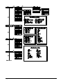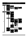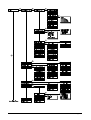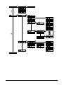
1
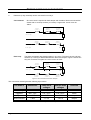
® ADVISOR CD 7203 CD95/15003 Installation Manual Software from Version: V6.0 142359999-2 COPYRIGHT SLC BV 1996. All rights reserved. No part of this publication may be reproduced, transmitted, stored in a retrieval system, or transmitted in any form, or by any means - electronic, photocopying, recording, or otherwise - without the prior written permission of SLC BV. DISCLAIMER SLC BV makes no representations or warranties with respect to the contents hereof and specifically disclaim any implied warranties of merchantability or fitness for any particular purpose. Further SLC BV reserve the right to revise this publication and to make changes from time to time in the contents hereof without the obligation of SLC BV to notify any person of any such revision. HOW TO USE THIS MANUAL This manual contains installation details for the CD7203, CD9503 and CD15003. When used in conjunction with the Programming Manual and the User Manual, it provides the installation engineer with basic installation and programming information. Programming The 'Programming Manual' for the CD7203 or the CD9503/CD15003 covers all necessary aspects of programming the system. Everybody involved in installing or maintaining this panel should have access to a copy of this manual. The 'Programming Manual’ is available from your ARITECH national office. The ‘Programming Map’ for the various systems can be found at the end of this manual. Installation manual for CD72/95/15003 Page 3 CONTENTS INSTALLATION GUIDELINES...................................................................................................... 7 Before switching on the power .................................................................................................... 8 Figure 1. Separate alarm and tamper connection............................................................ 8 Figure 2. Joint connection of the alarm & tamper ............................................................ 8 Figure 3. Overview of the dipswitches on remotes .......................................................... 9 PROGRAMMING GUIDE .......................................................................................................... 11 Figure 4. Keys on a CD30xx ......................................................................................... 11 Returning to default settings ..................................................................................................... 12 Leaving programming mode...................................................................................................... 13 Dialler ........................................................................................................................................ 13 Other manuals........................................................................................................................... 13 INSTALLATION GUIDE ............................................................................................................ 14 Wiring diagrams CD7203 .......................................................................................................... 14 Figure 5. CD7203 cabinet ............................................................................................. 14 Figure 6. CD7203 control panel .................................................................................... 15 Wiring diagrams CD9503/15003 ............................................................................................... 16 Figure 7. CD9503 cabinet ............................................................................................. 16 Figure 8. CD15003 cabinet ........................................................................................... 16 Figure 9. CD9503/15003 control panel.......................................................................... 17 Opening CD3008 / CD3048 keypad.......................................................................................... 18 Figure 10. Opening the CD3008 / CD3048 keypad....................................................... 18 Opening CD3009 / CD3049 keypad.......................................................................................... 18 Figure 11. Opening the CD3009 / CD3049 keypad........................................................ 18 CD3008 / CD3009 keypad ........................................................................................................ 19 Figure 12. CD3008 / CD3009 keypad ........................................................................... 19 CD3048 / CD3049 keypad ........................................................................................................ 19 Figure 13. CD3048 / CD3049 keypad ........................................................................... 19 CD9031 expander ..................................................................................................................... 20 Figure 14. CD9031 expander........................................................................................ 20 Keypad back tamper ................................................................................................................. 21 Connection of an extra power supply ........................................................................................ 22 Figure 15. Use of an extra power supply....................................................................... 22 Inputs ........................................................................................................................................ 22 Connection of a detector without memory................................................................................. 23 Figure 16. Dual loop connection of a detector without memory...................................... 23 Connection of a detector with Latch.......................................................................................... 23 Figure 17. Dual loop connection of a detector with latch................................................ 23 Connection of a key switch ....................................................................................................... 24 Figure 18. Connection of a key switch with LED's ......................................................... 24 Connection of a “nitewatch” system .......................................................................................... 24 Figure 19. Connection of a CP4005 Nitewatch PCB...................................................... 24 Page 4 Installation manual for CD72/95/15003 Connection of a fire detector ..................................................................................................... 25 Figure 20. Connection of a fire detector ........................................................................ 25 Outputs ..................................................................................................................................... 26 Connection of a relay or an LED ............................................................................................... 26 Figure 21. Connection of a relay or an LED on the output ............................................. 26 Connection of an AS256 and AS294/394 sounder ................................................................... 27 Figure 22. Connection of the AS294/394 + internal siren AS256 ................................... 27 Figure 23. Connection of the AS294/394....................................................................... 27 Printer output............................................................................................................................. 28 Figure 24. Printer connection ........................................................................................ 28 SPECIFICATIONS .................................................................................................................. 29 PROGRAMMING MAP CD7203............................................................................................... 31 PROGRAMMING MAP CD9503/15003.................................................................................... 35 Installation manual for CD72/95/15003 Page 5 INSTALLATION GUIDELINES The CD7203, CD9503/15003 control panels have been designed, assembled and tested to meet current standards of stability and resistance to electrical interference from the environment. If the following guidelines are followed, the system should give many years of reliable service. 1. Ensure that there is a good earth for the alarm system. A GOOD EARTH IS ESSENTIAL FOR EFFECTIVE RESISTANCE TO ELECTRICAL INTERFERENCE Do not forget to provide a (network) earth for the telephone dialler. 2. Maintain a good separation between low voltage and mains supply cables, and use separate points of entry into the control panel cabinet. 3. Avoid loops of wire inside the control panel and route cables so they do not lay on top or underneath the printed circuit board. The use of cable ties is recommended and improves neatness in the box. 4. Mains switching relays must NOT be fitted inside the control panel cabinet. The switching of these relays may cause electrical interference. 4.1 Use a relay with good insulation between the contacts and the coil. 4.2 Place a suppression diode (e.g. a 1N4001) across the relay coil. 4.3 Relays connected to open collector outputs of the alarm system should be rated at 12 volts DC with a coil impedance greater than 400 Ohms. 5. The remote bus cable is used for communication between the control panel and the keypads/expanders. The greatest care should therefore be taken when installing this cable. NEVER split this cable into separate cables. Do not use cables with wires which are used for TELEPHONE connections or for switching, for example, flashing lights, sirens or relays. 6. Avoid cable ducts and cable ways which contain mains power cables. This is particularly important when such ducts contain cables supplying electric motors, fluorescent lights or 3-phase power. If this is not possible, shielded cable should be used and the cable should be earthed at the control panel end ONLY. Installation manual for CD72/95/15003 Page 7 BEFORE SWITCHING ON THE POWER 1. Detectors (or key switches) can be connected in two ways: Conventional: One zone each is required for both tamper and the alarm. Both zones should be closed with an end-loop resistor (4.7 kOhm). Program the ‘zones’ menu as ‘Alarm’ A larm contact 1 A larm contact 2 A larm contact 3 Zone input 4K7 Tamper contact 1 Tamper contact 2 Tamper contact 3 Zone input 4K7 Figure 1. Separate alarm and tamper connection Dual loop: The alarm and tamper are placed together in one zone. The zone has two end-loop resistors (4.7 kOhm) to differentiate between alarm and tamper. Figure 2 shows how they are connected. Program the ‘zones’ menu as ‘Dual’. A larm contact 1 Zone input A larm contact 2 A larm contact 3 4K7 Tamper contact 1 Tamper contact 2 4K7 Tamper contact 3 Figure 2. Joint connection of the alarm & tamper This connection method gives the following input values: The zone is Resistance Panel zone voltages Remote zone voltages Reaction on standby 3k5 - 6k2 2.1 - 2.8 V 4.7 - 6.8 V none triggered 6k6 - 11k7 2.9 - 3.6 V 6.9 - 8.6 V alarm open > 12k7 > 3.7 V > 8.7 V tamper short-circuited < 2k9 < 1.9 V < 4.6 V tamper Table 1. Operation of the inputs Page 8 Installation manual for CD72/95/15003 2. Set the DIP switches of all the remote keypads and expanders. Remote 1 must be a keypad. CD7203, remotes 2 to 4 must be keypads and remotes 5 and 6 expanders. CD9503/15003, remotes 2 to 8 can be keypads or expanders but remotes 9 to 16 must be expanders. ON 1 SD 2 3 4 ON 1 SD 2 3 4 ON 1 SD 2 3 4 ON 1 SD 2 3 CD95/150 Keypad 1 Remote 2 Remote 3 Remote 4 CD72 Keypad 1 (all off) Keypad 2 Keypad 3 Keypad 4 ON 1 2 3 2 3 4 Expander 1 Expander 2 1 SD 2 3 4 Expander 9 ON 1 CD95/150 only 1 SD Remote 6 ON CD95/150 only 4 ON Remote 5 CD95/150 CD72 SD SD 2 3 4 Expander 13 ON 1 3 4 Expander 10 ON 1 SD 2 3 1 SD 2 3 4 ON 1 Remote 7 SD 2 ON 4 Expander 14 ON 1 3 4 Expander 11 ON 1 SD 2 3 SD 2 3 4 Remote 8 SD 2 4 4 Expander 15 ON 1 SD 2 3 4 Expander 12 ON 1 SD 2 3 4 Expander 16 Figure 3. Overview of the dipswitches on remotes 3. Close the tamper switches on the remote keypads, expanders and the control panel. Also close all zones which can cause a direct alarm. If this is not done, the system will be triggered as soon as it is switched on. 4. Remove link LK1 or JP1 from the PCB so that it returns to default settings. Installation manual for CD72/95/15003 Page 9 5. Supply only mains power to the control panel. The system will power up in the ARMED state. Any zones that may be open will initiate a full alarm condition and the sounders will activate. Do not use a battery to power the system when installing or changing the installation. If there is a short circuit in the 12 volt power supply, the voltage regulators in the supply (together with the fuses) will prevent serious damage to the system The 12 volt power supply will decrease sharply in the event of a short circuit. If a short circuit should occur, remove the 12 volt connections one by one. When the connection with the short circuit is removed the power supply will return to 12 volts. NOTE: ONLY KEYPAD ONE IS OPERATIONAL. Every time power is removed from the system the control panel memorises its status. If power is restored to the panel, the system starts up again in this status (except if LK1/JP1 has been removed). 6. Enter ‘0’ followed by the default user code ‘1122’ at keypad 1. 'Disarm?’ is shown on the display. System then disarms. If the sirens have been activated, these will now stop. The status of the system or the time and date will now appear in the display. 7. N.B. Enter ‘0’ followed by the default engineer’s code ‘1278’ at keypad 1 and press ‘â â ’ to return to programming mode. Do not forget to initialise additional keypads and expanders with the menu: ‘INSTALL REMOTE’ Replace LK1/JP1. Page 10 Installation manual for CD72/95/15003 PROGRAMMING GUIDE 1. Take some time to become familiar with the overview of the programming maps which can be found at the end of this manual. 2. Any programming changes made may not take effect until you exit programming mode. 3. If while programming an option the message “No Privilege” is displayed, the configuration is “Split System” and you do not have access to all the areas. This may be caused by not obtaining “Extended Access” (Maintenance menu), or because one or more of the areas are armed. 4. The following keys may be used: DISPLAY ABC DEF GHI 1 2 3 JKL MNO PQR 4 5 6 STU VWX YZ 7 8 9 Cursor left á up Always enter a ‘0’ before entering an engineer/user code to prevent errors ! Accept ü End Cursor right 0 X Under keys 1 to 9 there are 3 letters of the alphabet: press the keys repeatedly to enter first the number, then the lower case letters and then the upper case letters. Keys 9 and 0 have special symbols such as the comma and space. The arrows move the cursor during entry. Press ‘ü ü ’ to accept an entry. Cancel an entry by pressing ‘X’. To delete a character, overwrite with another character or a space. â down Figure 4. Keys on a CD30xx Note: CD30xx stands for the keypads: CD3008, CD3048, CD3009 and CD3049 Installation manual for the CD72/95/15003 Page 11 RETURNING TO DEFAULT SETTINGS There are two methods of returning the system (not the dialler) to default settings, these are: 1. 2. The removal of JP1 (CD7203) or LK1 (CD9503/15003). Subject to the ‘Engineers Lock’ not being programmed, this method will return the panel to default settings without the use of an engineer’s code. Proceed as follows: - Remove both the battery and the mains power. - Remove jumper JP1/LK1. - Connect the mains power. Only keypad 1 is operational. The software version is displayed on the other keypads (if present). As the default setting is “armed” any open zones will trigger the system and the sounders will activate. Enter ‘0’ followed by the default code ‘1122’ to disarm the system. Use code ‘1278’ to return to programming mode. If the default codes are invalid, the system had ‘Engineers Lock’ blocking programmed. If the current engineers’ code is known use procedure 2, if not, then replacement of the PCB is the only way to gain access to programming mode. By programming. Use this method if ‘Engineers Lock’ blocking is active and the engineers’ code is known. Proceed as follows: - KEYPAD ONE MUST BE USED FOR THIS PROCEDURE ALL AREAS MUST BE DISARMED - Go to keypad 1. - Enter the installation engineers’ code. - If the system is split, you will be asked for an area number, enter 1, press ‘↓ ↓ ‘ and you will enter the ‘Maintenance’ section of the engineers programming menu. Accept this ‘ü ü ’ and use the down arrow key until ‘Extended Access’ is displayed. Accept this ‘ü ü ‘ to gain extended access, then press ‘X’ to return to ‘Maintenance’. - Press ‘7’, ‘6’ and ‘1’ successively. You are now in the menu ‘Miscellaneous’, ‘Factory Prog. Menu’, ‘Default Settings’. ‘Are you sure?’ flashes in the display. If ‘No Privilege’ appears, there are two possibilities: ◊ You are not at keypad 1 ◊ The system is split and you do not have access to all areas. Check this using ‘Extended Access’. Page 12 - Press accept (‘ü ü ’). ‘Wait ...’ appears in the display. - The system has now reverted to default settings. Installation manual for the CD72/95/15003 LEAVING PROGRAMMING MODE Before leaving programming mode use the ‘Show Open Zones’ facility under the ‘Maintenance’ menu (menu 1.3). If any zones shown are 24Hr zones (e.g. tamper or fire) the alarm will activate on leaving the engineers’ programming mode. If dual loop is programmed, the letter T will appear next to the zone number to indicate the tamper section of the loop is open. Procedure: a. Check for open 24Hr zones (see above). b. Press ‘X’ until ‘Goodbye’ is displayed. c. Press accept ‘ü ü ’. DIALLER The use of the RD6203 dialler is recommended. This dialler fits inside the control panel cabinet and is connected to the control panel’s PCB using the cable supplied. The dialler may also be programmed via the keypad. A separate manual is available for the dialler. OTHER MANUALS Programming Manual CD7203 or CD9503/15003 A fully documented programming information manual. Separate versions for the CD7203 and the CD9503/15003 User manual Details user options Manager Manual A user manual which examines the options in more depth. Intended for the manager. Programming Manual RD6203 Documented information on programming the RD6203 dialler Installation manual for the CD72/95/15003 Page 13 INSTALLATION GUIDE WIRING DIAGRAMS CD7203 Power supply adjustment (DO NOT ADJUST) Printer connector Fixing hole Main PCB Cable entries Transformer 230V connection BATTERY Fixing hole Fixing hole Main PCB RD6203 Dialler To hold lid in place while servicing the panel Figure 5. CD7203 cabinet Page 14 Installation manual for the CD72/95/15003 See section specifications J1 F6 F5 To RD6203 CD7203 Eprom 5 4 3 2 1 43 42 41 Outputs 40 39 A B C D 38 37 to keypads and 36 expanders 35 34 Line Fault 33 external tampering 32 Ext. Siren 31 Tamper 30 JP1 Tamper switch Processor 29 28 27 26 25 24 23 22 EEprom 8 Zones 21 20 19 18 17 16 15 14 F4 See section specifications F3 F2 F1 ∼∼−+ RS232 printer 1 2 3 4 18VAC Battery + − + − + − 13 12 11 10 9 8 7 1 External siren (O/put 19) Internal siren (O/put 18) Aux. power PL1 Figure 6. CD7203 control panel Installation manual for the CD72/95/15003 Page 15 WIRING DIAGRAMS CD9503/15003 LED “power on” Power supply adjustment (DO NOT ADJUST) Printer connector RS232 Fixing hole Fixing hole Memory card connector Main PCB Dialler connector Output expander socket Input expander socket Fold lid down (CD95) Cable entries Transformer Mains cable entry RD6203 Dialler BATTERY Fixing hole Fixing hole Figure 7. CD9503 cabinet Power supply adjustment (DO NOT ADJUST) Fixing hole Dialler connector Printer connector RS232 Memory card selector RD6203 Dialler Dialler connector Output expander socket Fuse holder Mains cable entry BATTERY Cable fixing points Transformer Screw holes for cover Wall fixing holes Pull forward Lift up Main PCB Opening the cabinet Unscrew the screws (2x) Remove earth connection Figure 8. CD15003 cabinet Page 16 Installation manual for the CD72/95/15003 Power output 18VAC External siren O/put 50 Internal siren O/put 49 Battery to keypads and remotes Printer RS232 60 59 58 57 56 55 54 53 52 51 50 49 48 47 ∼ ∼ + - + - + - + - A B C D F8 CD9005 F7 Output Expander F6 See section Specifications Output 41 to 48 F5 8 7 6 5 4 3 2 1 F4 F3 F2 Tamper Switch (CD95 only) F1 CD9503/ CD15003 46 45 44 43 42 41 40 39 8 Outputs 1 38 FTC/Reset (in) 37 line fault (in) 36 external tampering 35 tamper 34 siren 33 32 31 30 29 28 27 26 25 16 24 23 22 21 20 19 18 17 LK1 Zones CP4003 Input Expander Eprom zone 144 to 152 Connector memory card To RD6203 16 15 14 13 12 11 10 9 8 7 6 5 4 3 2 1 16 15 14 13 12 11 10 9 8 7 6 5 4 3 2 1 1 Figure 9. CD9503/15003 control panel Installation manual for the CD72/95/15003 Page 17 OPENING CD3008 / CD3048 KEYPAD Figure 10. Opening the CD3008 / CD3048 keypad OPENING CD3009 / CD3049 KEYPAD Lift up Push Remove screw if installed Push clip in with screwdriver and lift up cover Figure 11. Opening the CD3009 / CD3049 keypad Page 18 Installation manual for the CD72/95/15003 CD3008 / CD3009 KEYPAD Display contrast adjustment Keypad address setting switches Cable entry from top Fixing hole Push the side clip to remove PCB 1 2 3 4 5 6 7 8 9 Cable entry from back Fixing hole Extra screw to secure lid D C B A 4-wire bus connection Fixing hole 0 Cable entry from bottom Buzzer volume adjustment Figure 12. CD3008 / CD3009 keypad CD3048 / CD3049 KEYPAD Display contrast adjustment Keypad address setting switches Cable entry from top Zones ON Fixing hole 4 OFF Push side clip to remove PCB 3 2 1 2 3 Fixing hole Cable entry from back 1 4 Extra screw to secure lid 5 7 8 6 OB + D C B A 9 0 Buzzer Power connection Four-wire bus connection Fixing hole Jumper to cut Buzzer volume adjustment off Buzzer Cable entry from bottom Figure 13. CD3048 / CD3049 keypad Remote connections A B C D Installation manual for the CD72/95/15003 Connection to CD 7203 CD 9503/15003 38 37 36 35 50 49 48 47 Page 19 CD9031 EXPANDER Cable entry from top Fixing hole Fixing hole TAM OB OA D C B A Outputs Four-wire bus connection 1 2 Cable entry from back 3 Processor 4 Zones 5 6 Reverse tampering Cover tampering 7 8 Fixing hole Cable entry from bottom Fixing hole Expander Address setting switches Lid tamper with lid tamper = Link 1-2 without lid tamper = Link 2-3 Figure 14. CD9031 expander Remote connections A B C D Page 20 Connection to CD 7203 CD 9503/15003 38 37 36 35 50 49 48 47 Installation manual for the CD72/95/15003 KEYPAD BACK TAMPER • CD30xx base •. • When the keypad lid is not used, remove the hinge-slot blanking pieces from the base ‚and place them in the hinge-slot openings „. • For back tamper protection fix the screw through the hole into the wall ƒ. Installation manual for the CD72/95/15003 Page 21 CONNECTION OF AN EXTRA POWER SUPPLY An auxiliary power supply will be required if the voltage is too low as a result of large cable runs or the current demand is in excess of the panels current supply rating. To connect an extra power supply the ‘+’ of the panel must not be connected to the ‘+’ of the auxiliary power supply. Also do not connect the ‘+’ of different auxiliary power supplies together. If the auxiliary power supply is used to power a remote expander/keypad, connect the “+” of the four wire bus (“A”) to the “+” of the auxiliary power supply. A common reference is obtained by connecting together all power supplies “-”. IMPORTANT: NEVER INTERCONNECT POSITIVES OF POWER SUPPLIES ALWAYS INTERCONNECT NEGATIVES OF POWER SUPPLIES CD72/95/15003 To “Power Monitor” zone 4K7 Central power supply 4K7 + DE 4-wire bus - A B C D RC813 RC900 1 4 + + BU4 + Detects failure of the mains power - A B C D Detector, siren, relay, etc... Auxiliary power supply PG822 4-wire bus of keypad or expander Figure 15. Use of an extra power supply INPUTS panel CD7203 panel CD9503/15003 expander socket CD9503/15003 1....8 1....16 145....152 Numbering CD7203 Keypad 1 Keypad 2 Keypad 3 Keypad 4 9....12 13....16 17....20 21....24 Keypad 1 CD95/150 CD95/150 Remote 2 Remote 3 Remote 4 Expander 5 Expander 6 9....16 Remote 5 17....24 Remote 6 Remote 7 Remote 8 17....20 25....32 33....40 41....48 49....56 57....64 65....72 73....80 Remote 9 Remote10 Remote11 Remote12 Remote13 Remote14 Remote15 Remote16 81....88 89....96 97....104 105....112 113....120 121....128 129....136 137....144 Table 2. Numbering of the inputs Note: In the CD7203 the expanders have priority over the keypads ! Page 22 Installation manual for the CD72/95/15003 CONNECTION OF A DETECTOR WITHOUT MEMORY 4k7 1 2 4k7 A A 3 4 S S 6 7 5 Input zone Power supply Figure 16. Dual loop connection of a detector without memory CONNECTION OF A DETECTOR WITH LATCH 4k7 1 4k7 A A 3 4 2 Power supply S S 6 7 5 Input zone 8 Output “Latch” M W 9 10 Output “Walk test” Figure 17. Dual loop connection of a detector with latch Note: Before connecting, the cable between terminal 2 and terminal 10 should be removed! Installation manual for the CD72/95/15003 Page 23 CONNECTION OF A KEY SWITCH C NO 4k7 NC Input zone “key” 4k7 Key switch C NC Tamper +12V Output “Arm/Disarm” Output “System Clear” “Programme outputs for negative applied” Figure 18. Connection of a key switch with LED's CONNECTION OF A “NITEWATCH” SYSTEM 4K7 Input zone 4K7 CP 4005 Light zone 1 / Light zone 2 / Daylight zone Figure 19. Connection of a CP4005 Nitewatch PCB Page 24 Installation manual for the CD72/95/15003 CONNECTION OF A FIRE DETECTOR CD72/95/15003 O2 O3 + - O1 + This extra connection is only necessary if a continuous signal from the external siren is required O1 = “Fire reset -” O2 = “External siren” O3 = “Fire -” RC213 RC213 1 To terminal “5” of the RC213 relay. 2 3 4 1 5 2 3 4 5 To “+” terminal of the panel To siren control (Sc) 3 2 9 4 8 DB602 + DP611/ DI612/ DT613 1 7 4K7 6 OR 1 NO 5 C DB822 + DP803 2 NC 4K7 4K7 To “fire” zone 4K7 To “fire” zone Figure 20. Connection of a fire detector Note 1: If there are several detectors place them in parallel and cable the zones as described in figure 1 or 2 (see page 8). Note 2: This connection also applied for detectors which require a reset after an alarm, e.g. the GS900 etc. Note 3: The reset is performed after the second entry of a code after an alarm. Note 4: Programme zone loop as “Dual”. Note 5: Programme all outputs for negative applied “-”. Installation manual for the CD72/95/15003 Page 25 OUTPUTS panel Internal siren External siren CD7203 1....5 18 19 CD9503/15003 1....8 49 50 Output expander 41....48 Keypad 1 Remote 2 Remote 3 Remote 4 Remote 5 Remote 6 Remote 7 Remote 8 OA OB OA OB OA OB OA OB OA OB OA OB OA OB OA OB CD7203 6 7 8 9 10 11 12 13 14 15 16 17 CD95/150 9 10 11 12 13 14 15 16 17 18 19 20 21 22 23 24 Remote 9 Remote10 Remote11 Remote12 Remote13 Remote14 Remote15 Remote16 CD15003 OA OB OA OB OA OB OA OB OA OB OA OB OA OB OA OB 25 26 27 28 29 30 31 32 33 34 35 36 37 38 39 40 Table 3. Numbering of the outputs NB: In a keypad OA is the buzzer. OB does not exist in a CD3008 / CD3009 keypad. CONNECTION OF A RELAY OR AN LED +12 Volt NC NO +12 Volt R = 820Ω Output C Output Figure 21. Connection of a relay or an LED on the output The resistor R is necessary to adjust the current. This may not be greater than 40 mA. For most LEDs, however, a current of approximately 15 mA is sufficient. The resistance calculation is as follows: R= V 13,8V − Vled 13,8V − 2V = = = 787Ω I 15 mA 15mA When rounded off this is 820 Ohms. Page 26 Installation manual for the CD72/95/15003 CONNECTION OF AN AS256 AND AS294/394 SOUNDER CD7203 CD95/15003 32 33 35 36 11 52 10 51 30 31 33 34 13 54 8 57 12 53 39 39 + T Sc AS294 / AS394 Bc 4K7 T + T AS256 - T Figure 22. Connection of the AS294/394 + internal siren AS256 Programming CD7203 CD9503/15003 Beacon control internal siren control 01 Int Sir Sy + 18 Int Sir Sy - 01 Int Sir Sy + 49 Int Sir Sy - external siren control 19 Ext Sir Sy + 50 Ext Sir Sy + Table 4. Programming for the sirens NB: If the tampers must be placed in separate zones, they can be connected according to figure 1 (1 end-loop resistor) or figure 2 (2 end-loop resistors) (see page 8). Cut these 2 jumpers for negative Hold-Off. The other 2 jumpers for positive Hold-Off. Figure 23. Connection of the AS294/394 Installation manual for the CD72/95/15003 Page 27 PRINTER OUTPUT PL1 (CD72) PL4 (CD95/150) DB25 RS232 PL1 (CD72) PL4 (CD95/150) DB9 RS232 Figure 24. Printer connection Page 28 Installation manual for the CD72/95/15003 SPECIFICATIONS FUSES CD7203 CD9503/15003 230 V fuse 315 mA 20x5 230 V fuse 315 mA 20x5 F1 Battery 2A 20x5 F1 Dialler 800 mA 20x5 F2 Auxiliary power 1A 20x5 F2 Output 8 800 mA 20x5 F3 Internal siren 1A 20x5 F3 Auxiliary power 1A 20x5 F4 External siren 1A 20x5 F4 Battery 3,15 A 20x5 F5 Dialler 1A 20x5 F5 External siren 800 mA 20x5 F6 Remotes 1A 20x5 F6 Internal siren 800 mA 20x5 F7 Remotes 800 mA 20x5 F8 Expander output 800 mA 20x5 230 VAC secondary fuse 315 mA Battery 12 Vdc, 16 Ah maximum for CD 7203 12 Vdc, 24 Ah maximum for CD 9503/15003 Max. power output max. 1.0 A, including remotes, dialler and unit for CD7203 max. 2.0 A, including remotes, dialler and unit for CD9503/15003 typ. Power consumption max. 66 mA CD 7203 CD 9503/15003 117 mA CD 3008/3009 26 mA 52 mA CD 3048/3049 30 mA 55 mA CD 9031 26 mA RD 6203 45 mA End of line resistors 95 mA 4k7, 2 %, 0.25W 1 resistor for Alarm loop 2 resistors for Dual loop Data bus A + 12V B GND C Data in (to panel) D Data out (from panel) Distance for data bus Max 1500m. Installation manual for the CD72/95/15003 Page 29 Dimensions (l x b x h) CD 3008/3048 160 x 120 x 35 (3 mm ABS) CD 3009/3049 160 x 120 x 35 (3 mm ABS) CD 9031 175 x 125 x 37 (3 mm polycarbonate) CD 7203/9503 315 x 385 x 88 (1,25 mm steel plate) CD 15003 475 x 460 x 160 (1,25 mm steel plate) Output no. Location Output connected max. Zone no. 1 to 5 control panel 100 mA 1 to 8 6 to 17 remotes 40 mA 9 to 24 18 internal siren CD7203 1A n/a 19 external siren CD7203 1A n/a Table 5. Overview of the inputs and outputs on the CD7203 Output no. Location Output connected max. Zone no. 1 to 8 control panel 100 mA (output 8 = 1 A) 1 to 16 9 to 40 remotes 40 mA 17 to 144 41 to 48 expanders 100 mA (output 48 = 1 A) 145 to 152 49 internal siren CD95/150 1A n/a 50 external siren CD95/150 1A n/a Table 6. Overview of the inputs and outputs on the CD9503/15003 Page 30 Installation manual for the CD72/95/15003 PROGRAMMING MAP CD7203 Installation manual for the CD72/95/15003 Page 31 Page 32 Installation manual for the CD72/95/15003 Installation manual for the CD72/95/15003 Page 33 Page 34 Installation manual for the CD72/95/15003 PROGRAMMING MAP CD9503/15003 Installation manual for the CD72/95/15003 Page 35 Page 36 Installation manual for the CD72/95/15003 Installation manual for the CD72/95/15003 Page 37 Page 38 Installation manual for the CD72/95/15003 Installation manual for the CD72/95/15003 Page 39 Page 40 Installation manual for the CD72/95/15003