1
HEAT CONTROLLER, INC.
Window-Type
Air Conditioner
MODELS: CD-121
CD-101-5
Service Manual
CAUTION
-Before servicing the unit, read the "safety precautions" in this manual.
-Only for authorized service personnel.
Air Conditioner Service Manual
TABLE OF CONTENTS
Safety Precautions..........................................................................................................................................3
Dimensions .....................................................................................................................................................5
Outside Dimensions ...................................................................................................................................5
Product Specifications ..................................................................................................................................6
Installation .......................................................................................................................................................7
Select the Best Location ...........................................................................................................................7
How to Install..............................................................................................................................................7
Installation Kits Content(Some Models) .....................................................................................................7
How to secure the Drain Pipe.....................................................................................................................9
Operation ......................................................................................................................................................10
Features ...................................................................................................................................................10
Insulation Resistance Test........................................................................................................................10
About the Controls on the Air conditioner ................................................................................................10
Disassembly ..................................................................................................................................................11
Mechanical Parts......................................................................................................................................11
Air Handling Parts ....................................................................................................................................12
Electrical Parts .........................................................................................................................................13
Refrigerating Cycle...................................................................................................................................14
Schematic Diagram.......................................................................................................................................17
Wiring Diagram.........................................................................................................................................17
Troubleshooting Guide .................................................................................................................................18
Piping System ..........................................................................................................................................18
Troubleshooting Guide .............................................................................................................................19
Room Air Conditioner Voltage Limits........................................................................................................21
2 Room Air Conditioner
Safety Precautions
Safety Precautions
To prevent injury to the user or other people and property damage, the following instructions must
be followed.
■ Incorrect operation due to ignoring instruction will cause harm or damage. The seriousness is
classified by the following indications.
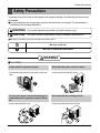
WARNING
This symbol indicates the possibility of death or serious injury.
CAUTION
This symbol indicates the possibility of injury or damage to properties only.
■ Meanings of symbols used in this manual are as shown below.
Be sure not to do.
Be sure to follow the instruction.
WARNING
■ Installation
Always install the expansion panel(s).
• No installation may cause fire and electric shock accident.
Do not use the power cord near flammable gas or
combustibles such as gasoline, benzene, thinner,
etc.
• It may cause explosion or fire.
Do not place the power cord near a heater.
• It may cause fire and electric shock.
Do not disassemble or modify products.
• It may cause failure and electric shock.
Gasolin
Service Manual 3
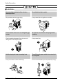
Safety Precautions
■ Installation
Never touch the metal parts of the unit when
removing the filter.
• They are sharp and may cause injury.
Ensure that the outer case is not damaged by age
or wear.
• If leaving appliance damaged, there is concern of
damage due to the falling of product.
Hold the plug by the head when taking it out.
• It may cause electric shock and damage.
4 Room Air Conditioner
Do not block the inlet or outlet.
• It may cause failure of appliance or accident.
Be cautious not to touch the sharp edges when
installing.
• It may cause injury.
Turn off the main power switch when not using it
for a long time.
• Prevent accidental startup and the possibility of injury.
Dimensions
Dimensions
Symbols Used in this Manual
This symbol alerts you to the risk of electric shock.
This symbol alerts you to hazards that could cause harm to the
air conditioner.
NOTICE
This symbol indicates special notes.
Outside Dimensions
W
H
D
Model
All Model
Dimension
W
mm(inch)
368(14 1/2")
H
mm(inch)
521(20 1/2")
D
mm(inch)
584(23)
Service Manual 5
Product Specifications
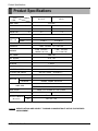
Product Specifications
MODELS
ITEMS
CD-101-5
CD-121
POWER SUPPLY
115V/60Hz
COOLING CAPAC
(Btu/H)
10,000
11,500
INPUT
(W)
1,050
1,210
RUNNING CUR
(A)
9.6
11.0
E.E.R
(BTU/W·h)
OPERATING
CONDITION
9.5
INDOOR
(℃)
26.7(DB)*
19.4(WB)**
OUTDOOR
(℃)
35(DB)*
23.9(WB)**
REFRIGERANT(R-22)CHARGE
480g(16.9oz)
655g(23.1oz)
EVAPORATOR
3 ROW
CONDENSER
2 ROW 23STACKS,
LOUVER FIN TYPE
16STACKS, SLIT FAN TYPE
3 ROW 16STACKS,
SLIT FAN TYPE
FAN,INDOOR
TURBO FAN
FAN,OUTDOOR
AXIAL FAN
FAN SPEEDS,FAN/COOLING
3/3
FAN MOTOR
6 POLES
OPERATION CONTROL
REMOTE CONTROLLER
ROOM TEMP . CONTROL
THERMOSTAT
AIR DIRECTION CONTROL
VERTICAL LOUVER (RIGHT&LEFT)
CONSTRUCTION
HORIZONTAL LOUVER (UP&DOWN)
PROTECTOR
COMPRESSOR
OVERLOAD PROTECTOR
FAN MOTOR
INTERNAL THERMAL PROTECTOR
3 WIRE WITH GROUNDING
POWER CORD
ATTACHMENT PLUG(CORD-CONNECTED TYPE)
DRAIN SYSTEM
NET WEIGHT
DRAIN PIPE SPLASHED BY FAN SLINGER
(lbs/kg)
OUTSIDE DIMENSION
(W×H×D)
NOTICE
(inch)
(mm)
77/35
79/36
141/2×201/2×23
368×521×584
SPECIFICATIONS ARE SUBJECT TO MINOR CHANGE WITHOUT NOTICE FOR FURTHER
IMPROVEMENT.
6 Room Air Conditioner
Installation
Installation
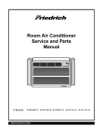
Installation Kits Contents
8
9
10
15
16
17
2
12
4
11
1
3
13
5
6
14
7
NO.
1
2
3
4
5
6
7
8
9
10
11
12
13
14
15
16
17
NAME OF PARTS
Curtain
Curtain Frame
Upper Guide
Side Guide
Support Bracket
Bracket
Leveling Bolt & Nut
Bolt
Nut
Washer
Side Guide seal
Foam Seal Strip
Window Track Seal
Window Locking Bracket
Screw (Type A)
Screw (Type B)
Screw (Type C)
QTY
1
1
1
2
1
1
1
2
2
2
1
1
1
1
9
3
8
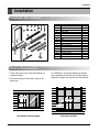
Window Requirements
1. These instructions are for a horizontal sliding or a
casement window.
2. The electrical outlet must be within reach of the
power cord.
For installation in a casement window, the window
frame assembly and the side of the building must be
adequate to support the weight of the air conditioner.
21"1 min.
40 /2" max.
21 1/2" min.
15 1/2"
min.
Horizontal sliding window
15 1/2" min.
16 1/2" max.
Casement window
Service Manual 7
Installation
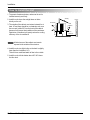
How to Install the Unit
1. To prevent vibration and noise, make sure the unit is
installed securely and firmly
Awning
2. Install the unit where the sunlight does not shine
directly on the unit.
NOTICE
All side louvers of the cabinet must remain
exposed to the outside of the structure.
4. Install the unit at a slight incline so the back is slightly
lower than the front(about 1/4").
This will force condensed water to flow to the outside.
5. Install the unit with the bottom about 30"~60" above
the floor level.
8 Room Air Conditioner
Cooled air
30"~60"
3. The outside of the cabinet must extend outward for at
least 14" and there should be no obstacles, such as a
fence or wall, within 20" from the back of the cabinet
because it will prevent heat radiation of the condenser.
Restriction of outside air will greatly reduce the cooling
efficiency of the air conditioner.
Heat
radiation
About 1/4"
Over 20"
Fence
Installation
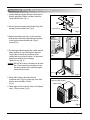
Horizontal Sliding Window Installation
1. Loosely attach the Support Bracket to the bottom of
Bracket using Bolts, Washer, and Nuts. Attach the
Leveling Bolt and Nut. (Fig. 1)
Bolt
Bracket
Washer
Nut
2. Remove protective backing from Window Track Seal
and apply seal to window track. (Fig.2)
Leveling Bolt & Nut
Support Bracket
Fig. 1
3. Measure and lightly mark a line 8-1/4 inches from
window jamb. Center the Support Bracket assembly
on the window track and fasten with 4 Type C
screws.(Fig. 2)
4. Put the Support Bracket against the outside wall and
tighten the Bolts on top of the Bracket. Adjust the
Leveling Bolt so that the air conditioner will be
installed with a very slight tilt (about 1/4") downward
toward the outside for proper drainage.
Tighten the nut. (Fig. 3)
NOTICE
Windo Jamb
Window
amb
1
8 /4 inches
Windo Track
Window
Seal
Windo Track
Window
Fig. 2
DO NOT drill a hole in the bottom of the base
pan. The air conditioner is designed to operate with the bottom of the base pan approximately half-full of water.
About 1/4"
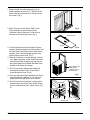
5. Fasten Side Guides to the sides of the Air
Conditioner using 3 Type A screws per Guide. Start
with first screw at middle of Guide.
(Fig. 4)
Type C screw
Ou
tsi
de
Wa
ll
Fig. 3
Fastening Side Guides
Upper Guide
6. Fasten Upper Guide on the top of the Air Conditioner
using 3 Type A screws. (Fig. 4)
Side Guide
Fig. 4
Service Manual 9
7. Measure height of window opening from top of
Bracket assembly as shown Fig. 5. Subtract 20-3/4
inches. Mark this measurement on Curtain and cut
the Curtain. (Fig. 5)
Fig. 5
8. Slide Curtain into Curtain Frame. Slide Curtain
Frame assembly into side Guides of the Air
Conditioner cabinet. Make sure Curtain is firmly
enclosed on all sides by the Frame. (Fig. 6)
Frame Curtain
9. Cut side Guide seal into 2 equal lengths. Remove
protective backing and apply it to the rear side of cabinet Side Guides, starting just below Curtain Frame
assembly. Pinch off excess length so seal is even
with the bottom of side Guide. (Fig. 7)
Curtain
Fig. 6
10. Place Air Conditioner in window opening. It should
sit on Bracket assembly so that Curtain Frame and
cabinet Side Guides are against top and side window jambs. Mate front of Bracket with Base Guide
attached to the bottom of base pan.
Apply weather seal
to side guides
just below edge of
Curtain Frame .
11. Drill 1/8 inch holes in window track through the
existing holes on Base Guide. Screw 4 Type C
screws through the holes. (Fig. 8)
Fig. 7
12. If this is a casement window installation, proceed to
Casement Window Installation. If not, slide inner
window sash firmly against side of the cabinet.
13. Drill 1/8 inch hole in window jamb to align with the
existing holes in the Curtain Frame. Attach Curtain
Frame to window frame with 2 Type B screws. (Fig.
8)
Base pan
Base Guide Bracket
Type B screw
Window Track
Type C screw
Window Track
10 Room Air Conditioner
Fig. 8
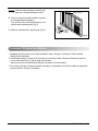
NOTICE
Check all seals and plug any remaining air
gaps with a suitable weatherproof caulk.
Foam seal strip
14. If this is a casement window installation, proceed
to Casement Window Installation.
If not, stuff the Foam Seal Strip between the vertical sash and the window glass. (Fig. 9)
15. Attach the L Bracket with a Type B screw. (Fig. 9)
Window
locking
bracket
Fig. 9
Casement Window Installation
1. Installation procedure is the same as that described in steps 1 through 11 and step 13 of the Horizontal
Sliding Window installation.
2. If the window opening is wider than 15-3/4 inches you will need to install a filler panel. Make this panel from
3/4 inch thick wood and run it the full length of the window.
Attach it securely to the window frame and paint it to protect it from the weather.
3. Since styles and sizes of casement windows vary widely, it is advisable to have the air conditioner installed by
someone skilled in this type of installation.
Service Manual 11
Operation
Operation
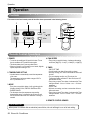
Controls
The remote control and control panel will look like those represented in the following pictures.
1
6
3
Power
1
Temp
2
Fan Speed
4
Timer
Mode
5
4
2
3
5
Remote Control Operations
1. POWER
• To turn the air conditioner ON, push this button. To turn
the air conditioner OFF, push the button again.
• This button takes priority over any other button.
• When you first turn it on, the unit is in cool mode, high fan
speed, temperature setting at 72˚F.
2. TEMPERATURE SETTING
• Use this button to automatically control the temperature
of the room.
The temperature can be set within a range of 60°F to
86°F by increments of 1°F.
3. MODE
- Every time you push this button, it will cycle through the
following modes: COOL, ENERGY SAVER and FAN.
- ENERGY SAVER
• The fan stops when the compressor stops cooling.
Approximately every 3 minutes the fan will turn on and
the unit will check the room air to determine if cooling is
needed.
4. FAN SPEED
• Every time you push this button, it advances the setting
as follows: {High(F3) → Low(F1) → Med(F2) → High(F3)}
5. TIMER
- SHUT-OFF TIME
• You will usually use shut-off time while you sleep.
• With unit running, use Timer to set number of hours until
shut-off.
• For your sleeping comfort, once Time is set, the
Temperature setting will raise 2°F after 30 min, and 2°F
after another 30 min.
• Every time you push Timer button, it advances the Timer
setting as follows: 1 Hour → 2 Hours → etc. → 12 Hours
maximum.
- START TIME
• With unit not running, use timer to set number of hours
before unit starts.
• Every time you push Timer button, it advances the Timer
setting as follows: 1 Hour → 2 Hours → etc. → 12 Hours
maximum.
6. REMOTE CONTROL SENSOR
AUTO RESTART
When power is restored after an electrical power failure, the unit will begin to run at its last setting.
12 Room Air Conditioner
Disassembly
Disassembly
- Before the following disassembly, set POWER SWITCH to OFF and disconnect the power cord.
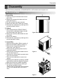
Mechanical Parts
1. Front Grille
D
1. Open the inlet grille downward and remove
the air filter.
2. Remove the screws which fasten the front
grille.(See Figure 1)
3. Pull the front grille from the right side.
4. Remove the front grille.(There are 4 hooks.)
5. Re-install the components by referring to the
removal procedure, above.
2. Cabinet
1. After disassembling the FRONT GRILLE,
remove the 6 screws which fasten the cabinet at both sides.(See Figure 2)
2. Remove the 4 screws which fasten the cabinet at back.
3. Remove the cabinet.
4. Re-install the components by referring to the
removal procedure, above.
Figure 1
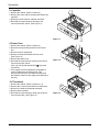
3. Control Box
1. Remove the front grille. (Refer to section 1)
2. Remove the cabinet. (Refer to section 2)
3. Remove the 1 screw which fasten the
power cord. (See Figure 3)
4. Disconnect the grounding screw from the
evaporator channel.
5. Remove the 2 screws which fasten the control box.(See Figure 3)
6. Remove the housing which connects motor
wire in the control box.
7. Remove three leads which connect compressor.
8. Discharge the capacitor by placing a 20,000
ohm resistor across the capacitor terminals.
9. Raise the control box upward completely.
10. Re-install the components by referring to
the removal procedure, above.
(Refer to the circuit diagram found on pages
21~22 in this manual and on the control
box.)
Figure 2
Figure 3
Service Manual 13
Disassembly
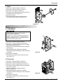
Air Handling Parts
4. Air Guide and Turbo Fan
1. Remove the front grille. (Refer to section 1)
2. Remove the cabinet. (Refer to section 2)
3. Remove the control box. (Refer to section 3)
4. Remove the 4 screws which fasten the brace.
5. Remove the brace.
6. Remove the 2 screws which fasten the upper air guide.
(See Figure 4)
7. Remove the upper air guide.
8. Remove the 2 screws which fasten the evaporator.
9. Move the evaporator forward and pulling it upward slightly. (See Figure 5)
10. Remove orifice by pulling two taps.
11. Remove the clamp with a hand plier which secures the
turbo fan.
12. Remove the turbo fan. (See Figure 6)
13. Remove the motor. (Refer to section 11)
14. Remove the 2 screws which fasten the lower air guide
from the base pan.
15. Remove the 2 screws which fasten the motor mount
from the base pan.
16. Remove the 2 screws which fasten the lower air guide
and motor mount.
17. Move the lower air guide backward and pull out from
the base pan. (Move the lower air giude carefully.)
18. Re-install the components by referring to the removal
procedure, above.
Figure 4
Figure 5
5. FAN
1. Remove the cabinet. (Refer to section 2)
2. Remove the brace (Refer to section 4)
3. Remove 6 screws which fasten the condenser.
4. Move the condenser to the right carefully.
5. Remove the clamp with a hand plier which secures the fan.
6. Remove the fan. (See Figure 7)
7. Re-install by referring to the removal procedure.
14 Room Air Conditioner
Figure 6
Disassembly
5. Shroud
1. Remove the fan. (Refer to section 2.5)
2. Remove the shroud. (See Figure 8)
3. Re-install the components by referring to the
removal procedure, above.
Electrical Parts
Figure 8
6. Overload Protector
1. Remove the cabinet. (Refer to section 2)
2. Remove the nut which fastens the terminal cover.
3. Remove the terminal cover. (See Figure 9)
4. Remove all the leads from the overload protector.
5. Remove the overload protector.
6. Re-install the components by referring to the
removal procedure, above.
7. Compressor
1. Remove the cabinet. (Refer to section 2)
2. Discharge the refrigerant system using a FreonTM
Recovery System.
If there is no valve to attach the recovery system,
install one (such as a WATCO A-1) before venting
the FreonTM. Leave the valve in place after
servicing the system.
3. Remove the overload protector. (Refer to section 6)
4. After purging the unit completely, unbraze the suction and discharge tubes at the compressor connections.
5. Remove the 3 nuts and the 3 washers which
fasten the compressor.
6. Remove the compressor. (See Figure 10)
7. Re-install the components by referring to the
removal procedure, above.
Figure 9
Figure 10
Service Manual 15
Disassembly
8. Capacitor
1. Remove the cabinet. (Refer to section 2)
2. Remove the screw and the clamp which fastens the
capacitor.
3. Disconnect all the leads of capacitor terminals.
4. Re-install the components by referring to the
removal procedure, above. (See Figure 11)
Figure 11
9. Power Cord
1. Remove the cabinet. (Refer to section 2)
2. Disconnect the grounding screw from the control
box.
3. Disconnect the 2 receptacles.
4. Remove a screw which fastens the clip cord.
(See Figure 12)
5. Remove the power cord.
6. Re-install the component by referring to the above
removal procedure, above.
(Use only one ground-marked hole
for ground
connection.)
7. If the supply cord of this appliance is damaged, it
must be replaced by the special cord. (The
special cord means the cord which has the same
specification marked on the supply cord attached at
the unit.)
Figure 12
10. Thermostat
1. Remove the cabinet. (Refer to section 2.1.2)
2. Remove the 2 screws which fasten the thermostat.
3. Disconnect 2 leads of thermostat terminals.
4. Remove the thermostat.
5. Re-install the components by refering to the above
removal procedure. (See Figure 13)
16 Room Air Conditioner
Figure 13
Disassembly
11. Motor
1. Remove the cabinet. (Refer to section 5)
2. Remove the turbo fan. (Refer to section 5)
3. Remove the fan. (Refer to section 6)
4. Remove the 4 screws which fasten the motor from
the Motor Mount. (See Figure 14)
5. Remove the motor.
6. Re-install the components by referring to the
removal procedure, above.(See Figure 14)
Figure 14
Refrigerating Cycle
12. CONDENSER
CAUTION
Discharge the refrigerant system using a
FreonTM Recovery System.
If there is no valve to attach the recovery
system, install one (such as a WATCO A-1)
before venting the FreonTM. Leave the valve in
place after servicing the system.
1. Remove the cabinet. (Refer to section )
2. Remove the 4 screws which fasten the brace.
3. Remove the 4 screws which fasten the condenser
and shroud. (See Figure 15)
4. Remove the 2 screws which fasten the condenser
and base pan.
5. After discharging the refrigerant completely,
unbraze the interconnecting tube at the condenser
connections.
6. Remove the condenser.
7. Re-install the components by referring to notes.
(See Figure 15)
Figure 15
13. Evaporator
1. Remove the cabinet. (Refer to section 2)
2. Remove the control box.(Refer to section 3)
3. Remove the upper air guide. (Refer to section 4)
4. Remove the 2 screws which fasten the evaporator
from lower air guide.
5. Move the evaporator sideways carefully.
(Refer to section 4)
6. After discharging the refrigerant completely,
unbraze the interconnecting tube at the evaporator
connections.
7. Remove the evaporator.
8. Re-install the components by referring to notes.
(See Figure 16)
Figure 16
Service Manual 17
14. Capillary Tube
1. Remove the cabinet. (Refer to section 2)
2. After discharging the refrigerant completely,
unbraze the interconnecting tube at the capillary
tube.(See caution above)
3. Remove the capillary tube.
4. Re-install the components by referring to notes.
NOTES
— Replacement of the refrigerant.
1. When replacing the refrigerant, be sure to
Discharge the refrigerant system using a FreonTM
recovery System.
If there is no valve to attach the recovery system,
install one (such as a WATCO A-1) before venting
the FreonTM. Leave the valve in place after
servicing the system.
2. After discharging the unit completely, remove the
desired component, and unbraze the pinch-off
tubes.
3. Solder service valves into the pinch-off tube ports,
leaving the valves open.
4. Solder the pinch-off tubes with Service valves.
5. Evacuate as follows.
1) Connect the vacuum pump, as illustrated figure
17A.
2) Start the vacuum pump, slowly open manifold
valves A and B with two full turns counterclockwise and leave the valves open.
The vacuum pump is now pulling through valves
A and B up to valve C by means of the manifold
and entire system.
CAUTION
If high vacuum equipment is used, adjust valves
A and B so they are opened only slightly for a few
minutes, then open slowly with the two full turns
counterclockwise. This will keep oil from foaming
and being drawn into the vacuum pump.
3) Operate the vacuum pump for 20 to 30 minutes,
until 600 microns of vaccum is obtained. Close
valves A and B, and observe vacuum gauge for
a few minutes. A rise in pressure would
indicate a possible leak or moisture remaining in
the system. With valves A and B closed, stop
the vacuum pump.
4) Remove the hose from the vacuum pump and
place it on the charging cylinder. See figure 17B.
Open valve C.
Discharge the line at the manifold connection.
5) The system is now ready for final charging.
18 Room Air Conditioner
6. Recharge as follows :
1) Refrigeration cycle systems are charged from the
High-side. If the total charge cannot be put
in the High-side, the balance will be put in the
suction line through the access valve which you
installed as the system was opened.
2) Connect the charging cylinder as shown in figure
17B.
With valve C open, discharge the hose at the
manifold connection.
3) Open valve A and allow the proper charge to
enter the system. Valve B is still closed.
4) If more charge is required, the high-side will not
take it. Close valve A.
5) With the unit running, open valve B and add the
balance of the charge.
a. Do not add the liquid refrigerant to the Lowside.
b. Watch the Low-side gauge; allow pressure to
rise to 30 lbs.
c. Turn off valve B and allow pressure to drop.
d. Repeat steps b. and c. until the balance of the
charge is in the system.
6) When satisfied the unit is operating correctly,
use the pinch-off tool with the unit still running
and clamp on to the pinch-off tube. Using a tube
cutter, cut the pinch-off tube about 2 inches from
the pinch-off tool. Use sil-fos solder and solder
pinch-off tube closed. Turn off the unit, allow it to
set for a while, and then test the leakage of the
pinch-off connection.
Disassembly
Equipment needed: Vacuum pump, Charging cylinder, Manifold gauge, Brazing equipment. Pin-off tool capable
of making a vapor-proof seal, Leak detector, Tubing cutter, Hand Tools to remove components, Service valve.
COMPOUND GAUGE
CONDENSER
(HIGH PRESSURE SIDE)
MANIFOLD
GAUGE
A
B
CAPILLARY TUBE
SEE INSETS
BELOW
EVAPORATOR
(LOW PRESSURE SIDE)
COMPRESSOR
LOW
HI
A
B
B
A
EXTERNAL
VACUUM PUMP
CHARGING
CYLINDER
C
Figure 17A-Pulling Vacuum
Figure 17B-Charging
Service Manual 19
Schematic Diagram
Wiring Diagram
optional part
S/V4WAY
FAN
MOTOR
C
FAN
HERM
1
3
3
1
1
3
3
SMW250-04
CN-TH1
R03H
10K
X
CN-4WAY
O
O
R03H
X
X
RY-HI
O
RY-4WAY
12V
RY-MED
RY-4WAY
1
1
SMW250-04
CN-TH2
Heat Pump
Cool Only
Model
CN-4WAY
YW396-03AV
3
3
O
X
CN-TH2
RY-COMP
RY-SYNC
RY-4WAY
RY-LOW
RY-MED
D02D~D05D
1N4004
D03D
D02D
RY-HI
4
7
POWER TRANS
2
1
12V
5V
SYNC
COMP
OSC01B
8.00MG
25
37
18
5V
17
16
MICOM
38
R12F
20K
39
40
TMP87CH47U
19
1M
8
4WAY
20
R01B
7
36
5V
J01F
0.01
50V
C06D
5V
35
21
12.1K
1%
R22H
6
26
27
28
29
30
31
32
22
R01H
23
6.2K
1%
12.1K
1%
9
5
MED
HI
Buzzer
Receiver
33
34
1K
R02E 20
R01L
220
10V
C05D +
O
680pF
C01L
7805
IC02D
LED out3
12V
I
0.01
50V
C04D
24
R02H
12.1K
1%
R21H
10
HVB
LOW
5V
OR02H
11
4
OR01H
12
3
X
O
+
ION
2
R01E
1K
13
1
IC01D
1000
16V
C03D
7812
J01F
14
O
15
16
IC01M
ULN2004AF
DISPLAY
0.1
50V
C02D
I
88 SEGMENT TYPE
LED TYPE
D05D
1000
35V
D04D
+
C01D
VSS
SLIDE SW
ROOM-TH
PIPE-TH
3
1
CN-MOTOR
1
RY-LOW
YW396-09AV
3
5
1
5
9
7
14D271
14D561
ZNR01J
120 1/2W
0.1/275V
C01J
9
1
3
FUSE
250V/T2A
R01J
7
1
3
CN-PWR
YW396-03AV
4
RY-COMP
G4A-1A-E-LG
41
15
42
14
12
44
1
2
3
4
5
6
7
8
9
10
11
Tx
C01A
0.01
R01A 1K
13
43
Rx
10uF
50V
C02A
100
R03A
3
R02A 4.7K
+
SEG-a
1
2
3.6V
IC01A
5V
S7136
C01P
0.01
EEPROM(optional part)
24LC01BT
1
Vcc 8
A0
2
7
A1
WP
3
6
A2
SCL
GND SDA 5
4
SDA
SCL
Digit4 (Scan4)
Digit2 (Scan2)
Digit3 (Scan3)
Digit1 (Scan1)
SEG-b
R01F
10K
R02F
10K
Digit0 (Scan0)
SEG-c
C02F
0.001
C01F
0.001
20K
20K
R03P
16
R02P
R04P
1K
1
15
12
14
11
3
5
10
2
6
9
13
7
4
IC01G
8
ULN2004AF
5V
Model
Auto Restart
Non Auto Restart
X
O
O
X
EEPROM R04P
1-6
1-13
1-12
1-11
1-10
1-7
1-6
1-13
1-12
1-11
1-10
Vout
Vcc
GND
RECEIVER
+
5V
C22L
220
10V
5V
5V
Q04G
A101S
Q01G
1-5
A101S
Q02G
1-5
A101S
Q03G
1-4
A101S
1-4
a
c
e
f
Digit0
SW6
POWER
1-3
FAN
SW1
MODE
SW4
Digit1
f
g
d
88 SEGMENT
0.4 inch
d
g
a
5
1-3
D01F
D06F
1-2
TIMER
SW2
TEMP DOWN
SW5
8
9
3
e
10
1-2
D02F
D05F
D04F
1-1
SW7
TEMP UP
D07F
a
b
c
6
4
7
1
b
1-1
BZ01E
PKM13EPY
-4000-A0
COOL
e
DRY/HEAT
f
d
FAN
TIMER
E/SAVER
e
g
f
d
c
b
a
CN-DISP1
1-7
1-8
2-2
1-9
2-3
1-8
2-2
g
CN-DISP2
1-9
2-3
2-4
2-1
2-4
2-1
CN-MAIN1
150
150
150
R01G
150
150
R02G
150
R03G
R05G
R04G
R06G
150
CN-MAIN2
R07G
b
c
5V
20 Room Air Conditioner
CAPACITOR
MAIN POWER
COMP
3
SEG-d
VAref
KEY0
TEST
SEG-e
Room TH
KEY1
/Reset
SEG-f
Pipe TH
LED out0
Osc out
VDD
Option1
LED out1
Osc in
SEG-g
Option2
LED out2
Schematic Diagram
Wiring Diagram
CASEMENT_10K
CASEMENT_12K
WIRING DIAGRAM
CN-MAIN2
CAPACITOR
YL
F
C
BK
CN-PWR
WH(BL)
(Ribbed)
DC12V
ZNR01J
RD
H
CN-TH1
POWER
TRANS
OR(BR)
CN-DISP2
DISPLAY PCB
ASSEMBLY
SWITCH
CN-12V
FUSE
250V/T2A
(115V/T2A)
BK(BR)
(Plain)
CN-DISP1
THERMISTOR
CN-MAIN1
RY-HI
MOTOR
CN-MOTOR
RY-MED
BK
BL
RD
YL
OR
RY-LOW
GN/YL
CN-HVB
H.V.
ASSEMBLY
3
GN/YL
R
COMP.
4
S
BL
C
OLP
RY-COMP
MAIN PCB
ASSEMBLY
BK
RD
AIR FILTER
ASSEMBLY
3854AR3629N
Service Manual 21
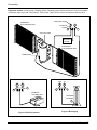
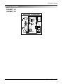
Components Location
Main P.W.B Assembly
C01J
R01J
LW1
CN_PWR
CN_4WAY
CN_MOTOR
ZNR01J
3
1
RY_LOW
RY_HI
RY_MED
RY_4WAY
TRANS
CN_MAIN2
4
4
D02D
CN_MAIN1
IC01D
D05D
FUSE
OSC01B
C01A
C02A
PCB ASM: 6871A01001
J02
R02A
J01
IC01A
J04
C05D
PCB: 6870A91001A
IC02D
C03D
R03H
RY_COMP
250V T3.15A
4
CN_TH2
3
250V T2A
C01D
CN_TH1
1
13
D03D
D04D
7
1
J03
Display P.W.B Assembly
2003.08.22
SEGMENT
1
1
LED4
FAN
MODE
LED1
COOL
J8
J7
J6
BZ01E
J3
D06F
SW4
CN_DISP2
CN_DISP1
C22L
SW6
POWER
SW5
SW7
TEMP DOWN
TEMP UP
D02F
D04F
D07F
J1
D05F
D01F
J5
RECEIVER
SW1
SW2
J2
PCB P/NO : 6870A90166A
22 Room Air Conditioner
J4
LED3
TIMER
F/SPEED
TIMER
PCB ASM P/NO : 6871A20442
LED2
DRY/HEAT
LED5
E/SAVER
Troubleshooting Guide
Troubleshooting Guide
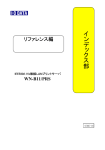
Piping System
CONDENSER COIL
FAN
CAPILLARY TUBE
MOTOR
COMPRESSOR
TURBO FAN
EVAPORATOR COIL
Following is a brief description of the important components and their functions in the refrigeration system.
Refer to Fig. 18 to follow the refrigeration cycle and the flow of the refrigerant in the cooling cycle.
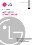
ROOM AIR CONITIONER
CYCLE OF REFRIGERATION
EVAPORATOR COILS
CONDENSER COILS
COMPLETE LIQUID
BOIL OFF POINT
COOLED
AIR
SUCTION LINE
COOL LOW PRESSURE VAPOR
VAPOR INLET
HOT
DISCHARGED
AIR
ROOM AIR HEAT LOAD
MOTOR
OUTSIDE COOLING
AIR FOR REFRIGERANT
PASS THROUGH
COMPRESSOR
OIL
LIQUID
PRESSURE
DROP
LIQUID OUTLET
(LIQUID REFRIGERANT)
HIGH PRESSURE VAPOR
LIQUID REFRIGERANT
CAPILLARY TUBE
LOW PRESSURE VAPOR
Figure 18
Service Manual 23
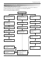
Troubleshooting Guide
Troubleshooting Guide
In general, possible trouble is classified in two kinds.
The one is called Starting Failure which is caused from an electrical defect, and the other is ineffective Air
Conditioning caused by a defect in the refrigeration circuit and improper application.
Unit is running but cooling is ineffective.
Ineffective Cooling
Check cold air circulation
for smooth flow.
Check outdoor coil
(heat exchanger) & the fan
operation.
Dirty indoor coil
(Heat exchanger)
Check gas leakage.
Check heat load
increase.
Clean condenser.
Not on separate circuit.
Malfunction of fan
Clogged of air filter.
Repair gas leak.
Replace of unit if the
unit is beyond repair.
Obstruction at air outlet
Check inside gas
pressure.
Adjusting of refrigerant
charge.
Correct above problem
Malfunction of compressor.
Check clogging in refrigeration system.
Repair clogging in refrigeration system.
24 Room Air Conditioner
Replacement of
compressor.
Satisfactory operation with
temperature difference of
inlet & outlet air ;
44~50°F(7~10°C)
Troubleshooting Guide
Fails to Start
Check of power source.
Check circuit breaker
and fuse.
Check of control switch
setting.
Gas leakage of feeler bulb
of thermostat
Check of control switch.
Compressor only fails to
start.
Fan only fails to start.
Improper wiring.
Drop of power voltage.
Improper thermostat setting.
Defect of fan motor
capacitor.
Defect of compressor
capacitor.
Loose terminal connection.
Capacitor check.
Irregular motor resistance
( ).
Irregular motor insulation
( ).
Improper wiring.
Replacement
Replacement of fan motor.
Irregular motor resistance (
)
Irregular motor insulation (
)
Tests normal but fails to start.
Replacement of compressor
(locking of rotor, metal).
Replacement of compressor
(Motor damaged)
Service Manual 25
Troubleshooting Guide
Room Air Conditioner Voltage Limits
NAME PLATE RATING
MINIMUM
MAXIMUM
AC 115V ±10%
AC 103.5V
AC 126.5V
COMPLAINT
Fan motor will not run.
CAUSE
REMEDY
No power
Check voltage at outlet. Correct if none.
Power supply cord
Check voltage to rotary switch. If none, check power
supply cord. Replace cord if circuit is open.
Wire disconnected or connection loose
Connect wire. Refer to wiring diagram for terminal
identification. Repair or replace loose terminal.
Capacitor (Discharge
capacitor before testing.)
Test capacitor.
Replace if not within ±10% of manufacturer's rating.
Replace if shorted, open, or damaged.
Will not rotate
Fan blade hitting shroud or blower wheel hitting
scroll. Realign assembly.
Units using slinger ring for condenser fan must have
1
/4 to 5/16 inch clearance to the base. If it hits the
base, shim up the bottom of the fan motor with
mounting screw(s).
Check fan motor bearings; if motor shaft will not
rotate, replace the motor.
Fan motor runs
intermittently
Revolves on overload.
Check voltage. If not within limits, call an electrician.
Test capacitor.
Check bearings. Does the fan blade rotate freely?
If not, replace fan motor.
Pay attention to any change from high speed to
low speed. If the speed does not change, replace the
motor.
Fan motor noise.
Compressor will not run,
but fan motor runs.
Fan
If cracked, out of balance, or partially missing,
replace it.
Turbo
If cracked, out of balance, or partially missing,
replace it.
Loose clamper
Tighten it.
Worn bearings
If knocking sounds continue when running or loose,
replace the motor. If the motor hums or noise
appears to be internal while running, replace motor.
Voltage
Check voltage.
If not within limits, call an electrician.
Wiring
Check the wire connections, if loose, repair or
replace the terminal. If wires are off, refer to wiring
diagram for identification, and replace. Check wire
locations. If not per wiring diagram, correct.
26 Room Air Conditioner
Troubleshooting Guide
COMPLAINT
Compressor will not run,
but fan motor runs.
CAUSE
Thermistor
REMEDY
Check the TEMP control. If not at the lowest number,
set TEMP control to this setting and restart the unit.
Check the continuity of the thermistor. Replace the
thermistor if the circuit is open.
Compressor cycles on
overload.
Compressor cycles on
overload.
Compressor cycles on
overload.
Insufficient cooling or heating
Excessive noise
Capacitor (Discharge
capacitor before servicing.)
Check the capacitor.
Replace if not within ±10% of manufacturers rating.
Replace if shorted, open, or damaged.
Compressor
Check the compressor for open circuit or ground. If
open or grounded, replace the compressor.
Overload
Check the compressor overload, if externally mounted. Replace if open. (If the compressor temperature
is high, remove the overload, cool it, and retest.)
Voltage
Check the voltage.
If not within limits, call an electrician.
Overload
Check overload, if externally mounted.
Replace if open. (If the compressor temperature is
high, remove the overload, cool, and retest.)
Fan motor
If not running, determine the cause. Replace if
required.
Condenser air flow restriction
Remove the cabinet. inspect the interior surface of
the condenser; if restricted, clean carefully with a
vacuum cleaner (do not damage fins) or brush.
Clean the interior base before reassembling.
Condenser fins (damaged)
If condenser fins are closed over a large area on the
coil surface, head pressures will increase, causing
the compressor to overload. Straighten the fins or
replace the coil.
Capacitor
Test capacitor.
Wiring
Check the terminals. If loose, repair or replace.
Refrigerating system
Check the system for a restriction.
Air filter
If restricted, clean or replace.
Exhaust damper door
Close if open.
Unit undersized
Determine if the unit is properly sized for the area to
be cooled.
Turbo or fan
Check the set screw or clamp. If loose or missing,
correct. If the turbo or fan is hitting air guide,
rearrange the air handling parts.
Copper tubing
Remove the cabinet carefully and rearrange tubing
not to contact cabinet, compressor, shroud, and barrier.
Service Manual 27
Specifications and performance data subject to change without notice.
HEAT CONTROLLER, INC.
1900 WELLWORTH AVENUE • JACKSON, MICHIGAN 49203
THE QUALITY LEADER IN CONDITIONING AIR
04/18/07
P/No.: MFL36458901