1
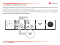
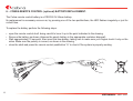
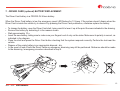
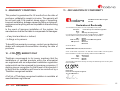
4625 - 4627
USER MANUAL
Summary
1. INTRODUCTION .................................................................................................................................................... 4
2. ARMING AND DISARMING THE SYSTEM WITH THE ORIGINAL VEHICLE REMOTE CONTROL OR WITH
THE COBRA REMOTE CONTROL .............................................................................................................................4
3. ACTIVE FUNCTIONS (functions description) .........................................................................................................5
4. FUNCTIONS PROGRAMMABLE BY A COBRA INSTALLER (functions description) .............................................7
5. EMERGENCY OVERRIDE ...................................................................................................................................10
6. REMOTE CONTROL BATTERY REPLACEMENT ................................................................................................ 11
7. DRIVER CARD BATTERY REPLACEMENT ........................................................................................................12
8. TROUBLESHOOTING GUIDE .............................................................................................................................13
9. WARRANTY TERMS .............................................................................................................................................14
10. UK MARKET ........................................................................................................................................................14
11. CONFORMITY DECLARATIONS ........................................................................................................................15
2
USER MANUAL 4625 - 4627
Dear Customer,
The product you’ve choosen is in line with the quality and functional standards required by the main Car Manufacturers and it
complies with the safety and security European directives. The technology used for the remote controls and the Driver cards
guarantees an high level of security toward attempts to reproduce the digital code. We would like to remind you that the security
degree of this system can be increased by adding the following modules:
LEVEL MONITOR
This sensor detect the vehicle being jacked up to for towing it away or for stealing the wheels.
HYPERFREQUENCY VOLUMETRIC SENSOR
It is a volumetric sensor for interior protection required for convertible vehicles as it is not sensitive to air movements.
CRANK INHIBITION
To add another crank inhibition to the system.
WINDOW CLOSING
Fitting this module the electric windows will raise automatically when the system is armed.
TRACKING DEVICE
Allow to track your vehicle and to send alerts to a Secure Operating Center.
In this manuals we’ve listed all the standard system functionalities and those you can ask to active to an authorized Cobra
fitting centre. Please read carefully this manual to get the full benefit from the product.
4625 - 4627 USER MANUAL
3
1. - INTRODUCTION.
This system is equipped with a built-in CAN interface
(Controller Area Network) that allows it to detect CAN data
from the electric vehicle platform. The system can be armed/
disarmed with the vehicle original remote control or with the
Cobra remote control (optional).
2. - ARMING AND DISARMING WITH THE VEHICLE
ORIGINAL REMOTE CONTROL OR WITH THE
COBRA REMOTE CONTROL (optional).
To arm the system press the door locking pushbutton of the
vehicle original remote control or the “A” pushbutton of the
Cobra remote control.
The disarming status is confirmed by:
• vehicle doors unlocking (only mod. 4627, with the Cobra
remote only if the CDL connections have been made);
• audible signals (if activated);
• flashes of the direction lights;
• LED of the emergency panel OFF.
Button B
The arming status is confirmed by:
• vehicle doors locking (only mod. 4627, with the Cobra
remote only if the CDL connections have been made);
• audible signals (if activated);
• flashes of the direction lights;
• LED of the emergency panel illuminated.
The protection features of the system become active after
a 25 s arming period has elapsed (when the LED of the
emergency panel starts blinking).
Button A
To disarm the system press the door unlocking pushbutton
of the vehicle original remote control or the “B” pushbutton
of the Cobra remote control.
B
A
Note: if also the Driver Card (optional) is provided it will
be also possible to arm and disarm the system by
pressing its pushbutton.
The system is delivered with a set of standard functionalities
(active functions). The installer is able to activate some
more functionalities (programmable functions) with an
impact on the security and comfort the system will offer.
The following are the lists of the two groups.
B
A
4
USER MANUAL 4625 - 4627
3. - ACTIVE FUNCTIONS.
3.1 - Interior protection with ultrasonic volumetric
sensor.
The system protects the vehicle interior with a volumetric
ultrasonic sensor. Any attempt to get into the vehicle will
be detected and the alarm will trigger.
3.2 - Perimetric protection with door open warning
diagnostic.
3.5 - Arming the system with the volumetric ultrasonic
protection disabled.
This function allows to arm the system leaving temporarily
disconnected the interior volumetric protection. The
protection must be disabled any time you leave somebody
or an animal in the vehicle. Also if you want to leave any
window opened please disable the protection to avoid false
alarms. All other protections remain active.
3.3 - Cable cutting protection (only for systems with
back-up battery siren).
To disable the volumetric protection proceed as follow:
switch the engine off being sure that the ignition switch
has been turned to the OFF position. Within 5 s press the
emergency panel pushbutton and keep it pressed until it
will flash once to confirm that the volumetric protection only
has been disabled. By keeping the pushbutton pressed
the system will confirm with two flashes that the additional
sensor input only has been disabled, with three flashes
for both of them disabled. The selected protection will
remain disabled until the system will be disarmed. It will
be automatically restored at the next arming.
The alarm will trigger if the system is not power supplied
(cutting of cables - battery disconnection) signaling the
sabotage.
Note: on some vehicles the system automatically disables
the volumetric protection if any windows is left
opened.
3.4 - Engine starting inhibition.
Ask your installer if this functionality is provided by the
system fitted on your vehicle.
The alarm will trigger by opening any door, boot and bonnet.
Should you have left any door opened while arming, the
system will signal it by 3 flashes of the direction lights and
3 audible signals (5 audible signals if the arming/disarming
audible signals function has been activated).
As soon as the system is armed the engine starting is not
be possible anymore.
4625 - 4627 USER MANUAL
5
3.6 - Emergency panel LED.
3.8 - Emergency disarming.
The LED main scope is to show the system arming and
disarming conditions. When the system is armed the LED
gets ON and remains illuminated until the 25 s arming
period has elapsed. After that it starts blinking. It goes OFF
as soon as the system is disarmed.
If the vehicle original remote control get lost or if it doesn’t
work, open the door with the mechanical key and turn the
ignition key ON. If the system doesn’t disarm automatically
follow the emergency procedure described in step 5.
3.9 - Direction lights alarm flashes.
3.7 - Alarms memory.
If the system has gone off (alarm ON) during the arming
time it will warn you with 3 flashes of the direction lights and
3 audible signals (5 audible signals if the arming/disarming
audible signals function has been activated). It also stores
in its memory the reason of the occurred alarm and shows it
on the emergency panel LED. Count the number of flashes
and check the corresponding alarm reason on the table. By
turning the key ON the memory will be deleted.
LED NUMBER
OF FLASHES
When the system goes off (alarm ON) the siren sounds
and the direction lights flash for 28 s.
ALARM
ROOT CAUSE
1 flash
Door opening detection.
2 flashes
Ultrasonic volumetric detection.
3 flashes
Bonnet opening detection.
4 flashes
Ignition key ON detection.
5 flashes
Boot opening detection.
6 flashes
Door opening detection.
7 ÷ 14 flashes
“Technical alarm” detection.
Contact your installer.
6
USER MANUAL 4625 - 4627
4. - PROGRAMMABLE FUNCTIONS.
4.5 - Passive engine starting inhibition.
4.1 - Activation and volume adjustment of the audible
arming and disarming signaling.
The starting inhibition becomes active after 115 s the
vehicle has been switched OFF. The starting inhibition is
immediately deactivated if the Driver Card (optional) is
detected or when a correct emergency PIN Code has been
digit on the emergency panel. This functionality is totally
independent from the other ones.
This function allows to activate a short audible signal to
confirm the system’s arming and disarming.
4.2 - Passive arming.
The system will automatically arm after 30 s the ignition
key has been switched off and the driver side door has
been opened and closed, so 30 s after the driver has left
the vehicle.
4.3 - Auto re-arming.
The system will automatically re-arm if, after 115 s, it has
been disarmed and no one door has been opened (nobody
gets on the vehicle).
4.6 - Only for mod. 4627, comfort window closing with
Cobra remote control (optional).
This is a native function of the vehicle, so at first check if it
is available. By keeping pressed the Cobra remote control
pushbutton “A” you can close the windows from a distance.
If not you can ask your installer to fit an additional window
closing module.
Warning: for safety reasons we recommend to close the
windows remaining close to the vehicle.
4.4 - Only for mod. 4627, auto re-arming with doors
locking.
As for auto re-arming, but doors will lock (if the CDL
connections have been made).
4625 - 4627 USER MANUAL
7
4.7 - Anti hi-jacking.
This function helps to prevent the vehicle hi-jack while
driving, taking care also to the safety of the driver. If the
driver isn’t recognized, the system will consider him as an
unauthorized person to drive the vehicle; it will generate
an alert sequence and it will not allow the engine starting
after it has been switched off.
During the normal usage of the vehicle the driver is
recognized by the system in two ways:
- manual (without Driver Card): by entering the first two
Pin Code digits on the emergency panel.
The driver must be recognized by the system every time
the ignition key is switched on or when, with the ignition
key on, the driver opens and closes the driver side door
to get off. If the recognition doesn’t happen within 60 s
the LED of the system starts to flash quickly, reporting
the failed recognition for further 30 s. When this time is
expired, the system generates an alert sequence also
if the engine is running. The engine cranking inhibition
becomes active with the ignition key off, making
impossible the engine running. To exit the anti hi-jack
function, enter the four digits of the Pin Code.
alert sequence also if the engine is running. The engine
cranking inhibition becomes active with the ignition key
off, making impossible the engine running. To exit the
anti hi-jack function, the system must recognize the
Driver Card. If the Driver Card is switched off, press the
push-button of the Driver Card to be recognized.
Warning: to temporarily deactivate the anti hi-jack function
(Driver Card broken or with flat battery), type the four digits
of the Pin Code. The function will become active again by
opening and closing the driver’s door when the ignition key
is on or by turning the ignition key ON and OFF.
Note: the function is as standard disabled in compliance
with the European regulation. Its activation voids the CE
homologation. It can be used only in the extra-European
countries, if the functionality is not in conflict with the local
rules.
- automatic (with Driver Card).
The driver must be recognized by the system when
it detects the Driver Card. If the recognition doesn’t
happen within 60 s the LED of the system starts to flash
quickly, reporting the failed recognition for further 30
s. When this time is expired, the system generates an
8
USER MANUAL 4625 - 4627
4.8 - Garage mode.
This function allows to temporarily disable all protection
automatic functionalities of the system. It can be used,
as an example, when you need to leave the vehicle at a
workshop for maintenance to avoid the automatic activation
of any functionality. When the garage function is active the
driver is allowed to turn the ignition key on for 10 times
(engine running). After 10 times the system restore all
automatic functionalities.
Activation
- Open driver side door.
- Turn the ignition key ON.
- Enter the complete emergency PIN Code (4 digits)
on the emergency panel pushbutton.
- A flash of the direction lights confirms the activation.
4.9 - Panic alarm from Cobra remote control (Cobra
remote control optional).
If the function is activated, pressing the “A”push-button of
the remote control, with the system armed and after the
inhibition time of 28 s has elapsed, it allows to generate a
10 s panic alarm. By activating this function it will not be
possible to activate the function described in step 4.10.
4.10 - Car finder by Cobra remote control (Cobra remote
control optional).
If the function is activated, pressing the “A”push-button of
the remote control, with the system armed and after the
inhibition time of 28 s has elapsed, it allows to generate
a 10 s cycle with the direction lights flashing and buzzer
sounding. By activating this function it will not be possible
to activate the function described in step 4.9.
Deactivation
- Lock then unlock the vehicle with the original remote
control.
- A flash of the direction lights and an audible signal
confirm the deactivation.
4625 - 4627 USER MANUAL
9
4.11 - Personalization Pin Code.
www.cobra-at.com
The Personal Identification Code is a four digits code which is already stored in the system. The sticker with the PIN code
must be applied by the installer on the PIN code card you should have got from your installer.
Keep the PIN code card always with you. The code is required to emergency override the system the remote control
doesn’t work or if you’ve lost it. The PIN code is also used for other scopes (driver recognition code for the anti hi-jack
functionality and as activation code for the garage mode). Upon your request and submitting the card to your installer, he
will personalize you the PIN code.
PIN
CODE
1122
4C4415A2A
S/N 0003 050524
PERSONAL
IDENTIFICATION
CODE
PIN
CODE
1122
We advise you to stick the PIN CODE, which may be found on the rear of the control unit, adhesive label on to the PIN
CODE CARD.
10
USER MANUAL 4625 - 4627
5. - EMERGENCY OVERRIDE WITH PIN CODE.
If the vehicle original remote control get lost or if it doesn’t work, open the door with the mechanical key and turn the ignition
key ON. If the system doesn’t disarm automatically proceed as follow:
press the emergency panel pushbutton for a number of times corresponding to the first digit of the PIN Code. Each
pushbutton pressure is confirmed by a quick flash of the LED. Make a longer pause to let the system understand that
you’ve finished to enter the first digit, a longer flashing of the LED will confirm it. Do the same for the remaining digits, as
soon as all four digits will be entered the system will disarm.
Press for a number of
times equal to the figure
in the PIN code
PIN CODE
SIREN
ON
OK
Short
flash
pause
ALARM
SYSTEM
DISARMED
Long
flash
Enter next
PIN CODE
figure
4625 - 4627 USER MANUAL
11
6. - COBRA REMOTE CONTROL (optional) BATTERY REPLACEMENT.
The Cobra remote control battery is a CR2032-3V lithium battery.
Its replacement is necessary as soon as, by pressing one of the two pushbuttons, the LED flashes irregularly or just for
a short time.
To replace the battery perform the following steps:
• open the remote control shell, being careful to lever it up in the point indicated in the drawing.
• Remove the battery as shown (dispose the empty battery in the appropriate container disposal).
• Wait approximately 10 seconds, then insert the new battery, taking care to make sure your fingers touch it only on the
sides. Make sure the polarity is correct, as shown in the drawing.
• close the shell and press the remote control pushbutton “A” to check if the system is properly working.
12
USER MANUAL 4625 - 4627
7. - DRIVER CARD (optional) BATTERY REPLACEMENT.
The Driver Card battery is a CR2032-3V lithium battery.
When the Driver Card battery is low the emergency panel LED flashes for 10 times. If the system doesn’t disarm when the
Driver Card is inside the vehicle try to disarm it by pressing the Driver Card pushbutton, otherwise replace the battery.
• To change the battery, open the Driver Card shell, being careful to lever it up at the point the area indicated in the drawing.
• Remove the battery by extracting it in the manner shown.
• Wait approximately 10 s.
• Insert the new battery, taking care to make sure your fingers touch it only on the sides. Make sure its polarity is correct, as
indicated in the diagram.
• Close the shell and press the Driver Card button checking that the system responds correctly. Perform the test near the
vehicle.
• Dispose of the empty battery in an appropriate disposal - bin.
• In the event of loss of both the Driver Cards an emergency disarming may still be performed. Reference should be made
to the disarming / emergency procedure described in step 5.
4625 - 4627 USER MANUAL
13
8. - TROUBLESHOOTING GUIDE.
THE REMOTE CONTROL DOESN’T ARM/DISARM THE SYSTEM.
Root cause
Countermeasure
a. If the system is armed, perform the emergency override procedure (see step 5).
The battery is empty.
b. Replace the battery. For Cobra remote controls see step 6, for the original remote control follow the
instructions of the vehicle “Use and maintenance” manual.
c. If you cannot solve the problem contact your installer.
THE SYSTEM HAS GENERATED A FALSE ALARM - CHECK ON THE EMERGENCY PANEL LED
(ALARM MEMORY FUNCTION) WHICH IS THE ALARM ROOT CAUSE.
Root cause
Countermeasure
a. Check if the windows and the roof have been closed.
Alarm generated by
the volumetric US
sensor.
b. Check if inside the vehicle there is any moving objects or any object that can move because of slow
air movements.
c. If you cannot solve the problem contact your installer.
Alarm generated by
door/boot/bonnet
opening.
a. Check if all doors/boot and bonnet have been closed.
b. If you cannot solve the problem contact your installer.
14
USER MANUAL 4625 - 4627
9. - WARRANTY CONDITIONS.
This product is guaranteed for 24 months from the date of
purchase, validated by receipt or invoice. The warranty will
be null and void if the product shows signs of tampering,
incorrect installation, damage caused by falling or transport,
negligence and anything else not imputable to manufacturing
defects.
In the event of improper installation of the system, the
manufacturer shall not be liable to compensate for damages:
- of any kind and direct or indirect;
- to things or to persons.
11. - DECLARATION OF CONFORMITY
Cobra
a Automotive Te
echnologies
CAT-V
VA
Declaration of Conformit
C
ty
The manufactu
urer hereby declares, at its sole responsib
bility, that the productt:
Description:
Model:
Type:
is in conformity
y with the essential re
equirements of the R&TTE
R
Directive 1999
9/5/EC.
The product ha
as been tested agains
st the following stand
dards and specificatio
ons:
EMC :
Healtth and Safety:
Rad
dio Spectrum:
To benefit from warranty coverage, contact your authorized
dealer with adequate documentation showing the date of
purchase.
10. - FOR UK MARKET ONLY
Thatcham recommends to its insurer members that the
installations of certified products within the aftermarket
are registered with an independent installation registration
system which can be accessed by insurance companies. If
seeking insurer recognition for the fitment of this product it
is likely that the installation will have to be carried out by a
Thatcham recognised installer.
Wireless
W
alarm systtem for automotive application
4600
4
4600
4
family with sirren type 5365
ECER10
E
Relevant
R
tests of EC
CER116 Regulation
n
EN50371
E
EN
E 300 220-1
EN
E 300 220-2
and declares th
hat the:
TRANSMITTER
RS Models 8702, 87
703, 8015 and 2771
conform to the
e essential requirem
ments of the Radio and
a
Telecommunica
ation Terminal Equip
pment
Directive 1999//5/EC in accordance to the following relev
vant standards and Directives:
D
Radio:
EMC:
Health & Safety:
EN
E 300 220-1/2
EN
E 301 489-1/3
EN
E 60950
EN
E 50371
a marked with the following CE markin
ng and Notified Body
y number according to
t the
The products are
Directive 1999//5/EC:
2011-10-14
4
Dario Parisi
ngineer
Products Homologation En
32 825111
Tel +39 033
A full list of Thatcham recognised installers is available at
www.thatcham.org/tri/home
4625 - 4627 USER MANUAL
15
The manufacturer shall not be liable for any faults or malfunctions in the anti-theft device and/or in the electrical system of the vehicle due to
incorrect installation and/or to failure to comply with the indicated technical specifications. The system must only be considered as a deterrent
agaist theft attempts.
Cobra Automotive Technologies
06DE3631A - 05/12
via Astico 41 - 21100 VARESE - ITALY
www.cobra-at.com