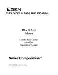
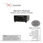
1
OPERATORS MANUAL MM 42 MONITOR PROCESSOR ENTER PUSH: FINE FILTER/SUB CONFIG DATA CANCEL COMPRESS MEMORY EQ UTILITIES LIMIT –4 –8 –12 –24 –36 –4 –8 –12 –24 –36 dBFS –4 PEAK –8 –12 –24 –36 GAIN REDUCTION –4 –8 –12 –24 –36 dB 10 6 1 CUE BUS A B INPUT C D +8 +4 0 –3 –12 –24 dBu 3 1 10 6 PUSH: SELECT 3 2 +8 +4 0 –3 –12 –24 OUTPUT dBu 1 4 6 0 10 2 LEVEL 8 MM 42 MONITOR PROCESSOR PHONES Quick Start We know you’re excited about the purchase of your new MM 42. But trust us: take your earphones out for a moment and read this Quick Start. It covers the basics to get you tweaking your ear mixes into submission in no time. The following paragraphs assume you’re working with a stereo (left/right) mix. For more advanced applications you’ll have to dig a bit deeper into this manual. First, the hardware. Connect the console aux/groups corresponding to the left and right ear mixes to the MM 42’s LINE INPUT A and LINE INPUT B respectively. Send the MM 42 a good, healthy signal, aiming to keep the loudest peaks around the -8 dBFS mark (yellow LEDs) on the INPUT meters. Running the Inputs “into the red” is only cool with old-school analog gear. If needed, make further adjustments using the INPUT controls. Turn the PHONES LEVEL all the way down and plug your earphones or headphones directly into either the ¼" or ⅛" PHONES jack. Slowly turn up the PHONES LEVEL to a comfortable listening volume. Not hearing anything? Press the CUE BUS button. Press the COMPRESS button and use the Previous and Next cursor keys to navigate to the M-BAND parameter. Rotate the DATA control clockwise until SET starts flashing. Don’t panic; instead, press the ENTER key to go to the Crossover Frequency page. Adjust the frequency splits for each range, pushing and turning the DATA control to make fine adjustments. Press the ENTER or COMPRESS key to return to the Compressor page. Adjust the THRSH parameter until you see a few blinky lights on the GAIN REDUCTION meter. Press the COMPRESS button again to move on to band 2, and again to move to 3, merrily making adjustments. No, you’re not hallucinating — the GAIN REDUCTION meter does indeed switch automatically to show you what’s happening within each frequency band. Okay, if you’re comfortable with getting around the various pages then the dry run is over. If you’re using a wireless transmitter, connect the MM 42’s main OUT 1 and OUT 2 to the inputs of the transmitter and adjust the transmitter’s input gain to a nominal level. If you’re using a hardwired beltpack, connect the MM 42’s main Outputs directly to the beltpack inputs, making sure the beltpack level is turned all the way down. Plug your earphones into the beltpack and slowly turn its level up to a comfortable listening volume. That’s it! You’re ready to rock. Or folk. Or country. Or polka….whatever your musical style. Tweak each processing section to taste, making sure you go to the MEMORY page once satisfied and store your hard work to one of the 16 available (preset) locations. There’s plenty more you can do with the MM 42. The rest of this manual covers important topics like using the SUB Output to augment an earphone mix with onstage subwoofers or “shakers”, handling two independent mono mixes with one MM 42, linking and unlinking parameters, connecting multiple MM 42s together via the Cue Bus, and the wonderful world of MIDI, just to name a few. So don’t stop here — keep reading! You still have 3 hours until show time. Contents Front Panel ....................................................................... 2 Rear Panel ........................................................................ 3 Connection Examples ..................................................... 4 Welcome Page ................................................................. 7 Basic Navigation & Editing ............................................. 7 Output Chain Configuration .......................................... 7 Adjusting Input & Output Levels ................................... 8 Signal Processing ............................................................ 9 Filters & Subwoofer .........................................................10 Multi-Band Compressor ................................................. 11 Parametric Equalization ................................................. 12 WEAR PARTS: This product contains no wear parts. Multi-Band Peak Limiter ................................................. 12 Using the Cue Bus ............................................................ 13 Storing and Recalling Memories (Presets) ....................14 Utilities ............................................................................. 14 Cue Bus Configuration .................................................... 14 Gain Reduction Meter Mode .......................................... 15 MIDI Configuration & Transfer ....................................... 15 Name Device ....................................................................16 Firmware Update ............................................................. 16 Restoring Factory Defaults............................................. 17 Appendix: Additional Resources ................................... 17 MIDI Implementation Chart ........................................... 18 Manual-1 MM 42 Front Panel 5 4 8 See Button Details below ENTER RANE MM 42 PERSONAL MONITOR PROCESSOR PUSH: FINE FILTER/SUB CONFIG CANCEL COMPRESS MEMORY EQ UTILITIES LIMIT 1 dB 10 2 A B INPUT C 3 6 1 CUE BUS DATA Button Details ENTER: Press this button to confirm flashing selections. GAIN REDUCTION –4 –8 –12 –24 –36 dBFS –4 PEAK –8 –12 –24 –36 –4 –8 –12 –24 –36 –4 –8 –12 –24 –36 D +8 +4 0 –3 –12 –24 dBu 6 3 1 10 PUSH: SELECT 3 6 2 +8 +4 0 –3 –12 –24 OUTPUT dBu 7 1 4 6 0 10 2 LEVEL 8 MM 42 MONITOR PROCESSOR PHONES 6 9 Cursor buttons: The Previous and Next buttons move the cursor through each of the parameter fields on a page. Alternately, push and release the DATA (2) control to “bump” from one field to the next. The currently selected parameter field is always displayed with either an underscore or with “<” and “>” brackets. CANCEL: Exits the current edit page and displays the welcome page. Also used to abort various operations. FILTER/SUB: Displays the edit pages for the Filter and Subwoofer sections. COMPRESS: Displays the edit pages for the 3-band Compressor. EQ: Displays the edit pages for the 5-band Parametric Equalizer. LIMIT: Displays the edit pages for the 3-band Limiter. CONFIG: Displays the edit page for Input and Output routing. MEMORY: Displays the edit page for storing and recalling Memories (Presets). UTILITIES: Displays the edit pages for Cue Bus Configuration, Gain Reduction Meter, MIDI Configuration, MIDI Transfer, Name Device and Firmware Update functions. CUE BUS: Activates the selected Output(s) on the Cue Bus for soloing purposes. The CUE BUS indicator lights when the Cue Bus is active. 1 Edit Pages: The 2x40 backlit LCD screen displays the edit pages for all MM 42 functions. 2 DATA control: Adjusts the currently selected parameter. Turning the DATA control clockwise increases the parameter, and turning it counterclockwise decreases the parameter. Push and turn the DATA control for fine adjustment of some parameters. The DATA control can also be “bumped” (push and release) to move the cursor between parameter fields. 3 INPUT Level controls: are digital trims to adjust each of the four Input gains. 4 INPUT Meters: are peak-reading, showing input headroom in dBFS. 0 dBFS equals +24 dBu. 5 GAIN REDUCTION Meters: Show the amount of gain reduction being applied to the currently selected Compressor or Limiter band, or the overall Compressor + Limiter gain reduction. (Depends on the currently selected Meter Mode. See the Gain Reduction Meter Mode section on page Manual-15 for details). 6 OUTPUT Meters: Averaging (rms) meters showing output level in dBu. 7 OUTPUT Level. Digital trim adjusts the main output levels. Also selects Outputs for cueing and editing in 2-Mono mode. 8 PHONES Level. Analog trim adjusts level of front panel PHONES jacks. 9 PHONES jacks. Stereo ¼" and ⅛" jacks allow direct connection of headphones or earphones to monitor the CUE BUS. Manual-2 MM 42 Rear Panel THIS DEVICE COMPLIES WITH PART 15 OF THE FCC RULES. MM 42 MIDI COMMERCIAL AUDIO EQUIPMENT 24TJ C R US LINE INPUTS OUTPUTS ALL BALANCED MADE IN U.S.A. RANE CORP. ACN 001 345 482 CUE OUT 1 C LISTED 100-240V 50/60 Hz 20 WATTS 9 FOR CONTINUED GROUNDING PROTECTION DO NOT REMOVE SCREW IN OUT / THRU CUE BUS CUE OUT 2 SUB 8 7 6 5 4 OUT 1 OUT 2 3 DIRECT OUTS D A B D C B A ALL BALANCED – TIP / PIN 2 = (+); SLEEVE = SIGNAL GROUND; PIN 1 = CHASSIS GROUND 2 1 1 LINE INPUTS A through D: Accept balanced or unbalanced, ¼" phone or XLR-style line-level inputs. 2 DIRECT OUTS A through D: are active balanced pass-throughs of corresponding Line Inputs. Use the DIRECT OUTS to daisy-chain common mixes to multiple MM 42s. 3 Main OUTPUTS: Balanced, line-level, XLR connections for OUT 1 and OUT 2. Wiring convention is pin 2 positive, pin 3 negative (return), pin 1 is shield chassis ground. Refer to the Sound System Interconnection RaneNote (included with this manual) for correct wiring when connecting to unbalanced destinations. 4 SUB Output: is balanced (tip-ring-sleeve). Connect to a subwoofer, amp/speaker combination or tactile “shakers” to add low-end thump to ear mixes. Refer to the Sound System Interconnection RaneNote when connecting to an unbalanced destination. 5 CUE OUT 1 and 2: is a balanced (tip-ring-sleeve), line-level Cue Bus Output. Connect to a spare transmitter or console inputs to monitor the Cue Bus signal. Signal is identical to the front panel PHONES jacks. The Cue Out level is not affected by the Phones Level control. 6 CUE BUS jacks: are RJ12 (telephone-style) for interconnecting multiple MM 42s for cueing (soloing) purposes. 7 MIDI OUT/THRU jack: Incoming MIDI data is automatically merged with outgoing MIDI data and passed to the OUT/ THRU if MIDI Merge mode is set to ON (see page Manual-15). 8 MIDI IN jack: Connect this input to the output of another MIDI device (sequencer, controller, MIDI-equipped PC, another MM 42, etc.) to accommodate data transfers, firmware updates, and external control. 9 Power connector: Uses the standard cord provided. The MM 42 has a universal internal switching power supply that accepts 100 to 240 VAC at 50 to 60 Hz, allowing it to work in most countries. Manual-3 Connection Examples The MM 42 is intended to be connected in-line between a mixing console and a wireless transmitter, hardwired beltpack or headphone amplifier. Stereo Mix with Optional Mono Subwoofer Output (default) In this configuration a standard Left/Right mix from the console is processed. The Left and Right signals (Inputs A and B) are summed to mono and assigned to the SUB Output. ACME Mixing Console Group/Aux Out 1 Mix Left Group/Aux Out 2 Mix Right LINE INPUT A LINE INPUT B ENTER * PUSH: FINE CONFIG DATA OUTPUT 1 MEMORY EQ UTILITIES LIMIT –4 –8 –12 –24 –36 dBFS –4 PEAK –8 –12 –4 –8 –12 –24 –36 GAIN REDUCTION –4 –8 –12 –24 –36 –24 –36 dB 10 CUE BUS A B INPUT C 6 1 D +8 +4 0 –3 –12 –24 dBu 3 1 10 PUSH: SELECT 6 3 2 +8 +4 0 –3 –12 –24 OUTPUT dBu 1 4 6 0 10 2 LEVEL 8 MM 42 MONITOR PROCESSOR PHONES Input 2 ACME In-Ear Stereo Transmitter (or wired beltpack) CONFIG Manual-4 COMPRESS OUTPUT 2 Input 1 * FILTER/SUB CANCEL CONFIG | | SUB OUT (optional) To powered subwoofer or bass shaker. MODE OUTPUT1 OUTPUT2 SUB STEREO A B A+B Monitor Engineer Two Independent Mono Mixes with Assignable Subwoofer Output In this configuration two independent mixes are processed separately. The SUB Output is fed from either Input A or Input B. ACME Mixing Console Group/Aux Out 1 Mono Mix 1 Group/Aux Out 2 Mono Mix 2 LINE INPUT A LINE INPUT B ENTER * PUSH: FINE CONFIG DATA OUTPUT 1 FILTER/SUB CANCEL COMPRESS MEMORY EQ UTILITIES LIMIT –4 –8 –12 –24 –36 dBFS –4 PEAK –8 –12 –4 –8 –12 –24 –36 GAIN REDUCTION –4 –8 –12 –24 –36 –24 –36 dB 10 CUE BUS A B INPUT C 6 1 D +8 +4 0 –3 –12 –24 dBu 3 1 10 PUSH: SELECT 6 3 2 +8 +4 0 –3 –12 –24 OUTPUT dBu 1 4 6 0 10 2 LEVEL 8 MM 42 MONITOR PROCESSOR PHONES OUTPUT 2 Input SUB OUT (optional) To powered subwoofer or bass shaker. ACME In-Ear Mono Transmitter 1 (or wired beltpack) Monitor Engineer Input ACME In-Ear Mono Transmitter 2 (or wired beltpack) CONFIG * CONFIG | MODE OUTPUT1 OUTPUT2 SUB A | 2-MONO A B INPUT A Assigned to SUB OUTPUT (optional) OR CONFIG * CONFIG | MODE OUTPUT1 OUTPUT2 SUB B | 2-MONO A B INPUT B Assigned to SUB OUTPUT (optional) Manual-5 Using the Direct Outputs The rear panel Direct Outputs provide a unity-gain pass-through of each input signal, pre-processing — allowing you to share a common aux/group feed across multiple MM 42s or to feed elsewhere. For example, create a single or stereo “full band” mix for a group of background singers, and send this feed from the console to Line Inputs A and B of the MM 42. Augment each person’s mix with an individual feed to Line Input C of each MM 42. Connect Direct Outs A and B to Inputs A and B of another MM 42. Repeat the process to daisy chain multiple MM 42s together. Use the front panel Input Levels to set the relative balance between mix elements (full band versus solo instrument) for each performer. Monitor Engineer ACME Mixing Console Aux 6 Keyboard Mix Aux 5 BG 2 Vocal Mix Aux 4 BG 1 Vocal Mix Aux 3 Lead Vocal Mix LINE INPUT C Aux 2 Band Mix Left Aux 1 Band Mix Right LINE INPUT A LINE INPUT B ENTER * CANCEL FILTER COMPRESS EQ LIMIT CONFIG MEMORY UTILITIES CUE BUS –4 –8 –12 –24 –36 A DATA –4 –8 –12 –24 –36 –4 –8 –12 –24 –36 B INPUT C DIRECT DIRECT OUTPUT OUTPUT A B LINE INPUT C INPUT: A CANCEL COMPRESS EQ LIMIT CONFIG MEMORY UTILITIES CUE BUS D 3 1 10 6 3 1 2 OUTPUT 4 6 0 10 2 LEVEL +8 +4 0 –3 –12 –24 8 MM 42 MONITOR PROCESSOR PHONES B INPUT GAIN REDUCTION –4 –8 –12 –24 –36 C B Stereo Transmitter Lead Vocals 10 6 3 1 10 6 1 D 3 1 2 +8 +4 0 –3 –12 –24 OUTPUT 4 6 0 10 2 LEVEL +8 +4 0 –3 –12 –24 8 MM 42 MONITOR PROCESSOR PHONES Stereo Transmitter Background Vocal 1 Stereo Transmitter Background Vocal 2 Stereo Transmitter Keyboard CUE BUS B ENTER CANCEL FILTER COMPRESS EQ LIMIT CONFIG MEMORY UTILITIES CUE BUS –4 –8 –12 –24 –36 –4 –8 –12 –24 –36 –4 –8 –12 –24 –36 A DATA DIRECT: A B INPUT GAIN REDUCTION –4 –8 –12 –24 –36 C B INPUT: A 10 6 3 1 10 6 1 D 3 1 2 +8 +4 0 –3 –12 –24 OUTPUT 4 6 0 10 2 LEVEL +8 +4 0 –3 –12 –24 8 MM 42 MONITOR PROCESSOR PHONES CUE BUS B ENTER * –4 –8 –12 –24 –36 –4 –8 –12 –24 –36 A INPUT: A LINE INPUT C –4 –8 –12 –24 –36 DATA * 6 1 +8 +4 0 –3 –12 –24 B FILTER DIRECT: A LINE INPUT C dB 10 CUE BUS ENTER * GAIN REDUCTION –4 –8 –12 –24 –36 DATA CANCEL FILTER COMPRESS EQ LIMIT CONFIG MEMORY UTILITIES CUE BUS –4 –8 –12 –24 –36 –4 –8 –12 –24 –36 –4 –8 –12 –24 –36 A B INPUT GAIN REDUCTION –4 –8 –12 –24 –36 C 10 6 3 1 10 6 1 D +8 +4 0 –3 –12 –24 3 2 +8 +4 0 –3 –12 –24 OUTPUT 1 4 6 0 10 2 LEVEL 8 MM 42 MONITOR PROCESSOR PHONES Analog Audio Cue Bus CONFIG * Manual-6 CONFIG | MODE OUTPUT1 OUTPUT2 SUB | STEREO A+C B+C A+B+C MM 42 Welcome Page Output Chain Configuration RANE CORPORATION MM 42 PERSONAL MONITOR PROCESSOR The welcome page displays the device name. This is the default page on power-up and any time the CANCEL button is pressed. The Name Device page of the UTIL menu is used to enter custom text to suit your liking – “MY GOLDEN EARS,” for example. See page Manual-16 for details. The Previous and Next buttons move the cursor through each of the parameter fields on a page. Parameter values are changed by rotating the DATA control. Repeatedly pressing a button cycles through all pages associated with a particular function. Each of the five Parametric EQ filters is a separate page within the EQ section, for example. In most cases parameter changes happen – and are heard instantly. In the few cases where they are not (when you are first prompted to answer a question, for example) the value flashes until the ENTER button is pressed. Pressing the CANCEL button on a flashing parameter automatically discards that parameter change. Coarse versus Fine Parameter Adjustment Parameters covering a large range – frequencies from 20 Hz to 20 kHz, or a Compressor Threshold from 0 dB to -60 dB for example – are adjustable in coarse and fine increments. Coarse adjustments help get you “in the ballpark” quickly, and are made by turning the DATA control in its normal out position. Fine adjustments allow you to really hone in on the parameter of interest (if you prefer the sound of 631 Hz instead of 630 Hz, for example) and are made by pushing in and holding the DATA control while turning it. The steps for coarse adjustment of frequencies follow the soundperson-friendly, ⅓-octave ISO (International Standards Organization) values you can probably recite in your sleep: 40, 50, 63, 80, 100, 125, 160, 200, 250…and so on. The steps for fine value adjustment of frequencies are broken into three ranges, as follows: Coarse ISO centers 20 - 800 Hz ISO centers 1k - 8k ISO centers 10k - 20k CONFIG | MODE OUTPUT1 OUTPUT2 SUB | STEREO A B A+B Output Chain Configuration Basic Navigation & Editing Range 20 - 999 Hz 1.0 kHz - 9.9 kHz 10 kHz - 20 kHz The MM 42 features four line-level Inputs, labeled A through D, which are assignable in any combination to either or both of the output signal chains and the SUB Output. Such an arrangement allows tremendous flexibility in setting up mixes. Press the CONFIG button. The default configuration is: Parameter Value Stereo Stereo mode; parameters within each processing section are automatically linked as OUT1+2. 2-Mono Dual mono mode; parameters within each processing section are automatically unlinked as separate OUT1 and OUT2. MODE OUTPUT1 OUTPUT2 SUB Description A, B, A+B, A+C, A+D, etc. Any Input or combination of Inputs (15 options total). Sets Input assignment for the Output 1 signal chain. Sets Input assignment for the Output 2 signal chain Sets Input assignment for Sub Output signal chain. The MODE parameter is highlighted by default. Rotate the DATA control to select between STEREO and 2-MONO (two independent mono mixes) mode. Assign one of the fifteen (!) input combinations to each output by selecting OUTPUT 1 or OUTPUT 2 and turning the DATA control to scroll through the various combinations. Repeat the process for the SUB output, if this output is being used to drive an external subwoofer or bass shaker. Fine 1 Hz 0.1 kHz 1 kHz If a frequency is currently set to a non-ISO value, making a coarse adjustment bumps the frequency to the next ISO center. For example, if a frequency is set at the non-ISO value of 75 Hz, increasing it by one coarse adjustment changes the frequency to the next ISO center of 80 Hz. Manual-7 Adjusting Input Levels Adjusting Output Levels The Input Levels page is automatically displayed any time an INPUT A/B/C/D control is adjusted. The Output Levels page is automatically displayed any time the OUTPUT control is adjusted. This page differs slightly depending on the currently selected configuration mode. In STEREO mode, use the and keys or bump (push and release) the OUTPUT control to navigate between the Output LEVEL and Left/Right BALANCE parameters. Rotate the OUTPUT control to adjust each parameter. INPUT | A B C D LEVELS | 0.0dB 0.0dB 0.0dB 0.0dB Input Levels Parameter INPUT A/B/C/D Value +12.0 dB to -40.0 dB Description Input level adjustment. Turn INPUT Level for 1 dB increments. Push and turn for 0.5 dB increments. OUTPUT | LEVEL | LEVEL <BALANCE> 0.0dB |<————|——————>| Output Levels (Stereo Mode) Parameter Value Description OUTPUT LEVEL +12.0 dB to -40.0 dB or off BALANCE Full left to full right Stereo output level adjustment. Turn OUTPUT Level for 1 dB increments. Push and turn for 0.5 dB increments. Stereo balance. In 2-MONO mode, use the and keys or bump (push and release) the OUTPUT control to navigate between the Output 1 and Output 2 Level parameters. Rotate the OUTPUT control to adjust each parameter. OUTPUT | LEVELS | 1 0.0dB 2 0.0dB Output Levels (2-Mono Mode) Parameter OUTPUT 1 LEVEL OUTPUT 2 LEVEL Value +12.0 dB to -40.0 dB or off Description Output 1 level adjustment. Turn OUTPUT Level for 1 dB increments. Push and turn for 0.5 dB increments. Output 2 level adjustment. Turn OUTPUT Level for 1 dB increments. Push and turn for 0.5 dB increments. To view a level setting without changing it simply push and release the control without turning it. The DATA control has no effect when adjusting Input and Output levels. Manual-8 Signal Processing Overview So what does the MM 42 have under the hood you ask? Plenty! Routing options allow the assignment of any combination of the four Inputs to any of the three Outputs: OUT 1, OUT 2 and SUB. Each of the processing chains for OUT 1 and OUT 2 features (in this order): Shelf/Cut Filters, a 3-band rms Compressor with fully adjustable crossover frequency points, 5-band fully Parametric EQ, and a 3-band Peak Limiter, also with fully adjustable crossover frequency points. The SUB output processing chain is completely independent of the main outputs and features adjustable Low- and High-Cut Filters for maximizing onstage thump. for an artist’s hearing difference between right and left ears, for example) or to process two completely independent mono mixes. To Link or Unlink an individual processing section: 1. Select the desired processing section. 2. Navigate to the Selected Output(s) field 3. Rotate the DATA control to select between adjusting parameters for OUT1+2 (linked) operation, OUT 1 only, or OUT 2 only. PEQ ON | EQ OUT 1+2| 1 A PEQ off| EQ OUT 1+2| 1 GAIN 0dB FREQ 100Hz OUTPUTS dBu +8 +4 0 –3 –12 –24 dB 10 A B C 6 3 1 10 6 BW (Q) 1/3 (4.3) If parameters are unlinked (OUT 1 or OUT 2, instead of OUT1+2), only the processing section for the currently selected output is bypassed. GAIN REDUCTION –4 –8 –12 –24 –36 BW (Q) 1/3 (4.3) Bypassing Processing Sections A wise man once said “it’s not a feature if you can’t turn it off.” Each processing section in the MM 42 can be turned off, allowing for quick before-and-after comparisons, or to bypass an unused section altogether. To bypass a processing section: 1. Navigate to the status area of the processing section. 2. Rotate the DATA control counter-clockwise until off is displayed. Linking and Unlinking Parameters within Processing Sections Parameters within each processing section can be linked or unlinked, depending on the application. Adjusting parameters in linked mode affects both outputs simultaneously and is particularly useful when working with Stereo mixes, as it allows you to change one set of parameters and affect both sides of the mix identically. Unlinking parameters allows you to make individual adjustments to each side of a stereo mix, (to account INPUTS dBFS FREQ 100Hz When OUT1+2 is selected, Output 2’s parameters are set to match those of Output 1. Note that OUT 2’s settings are not permanently overwritten. Switching back to OUT 2 restores them to their previous values. Why is the Output Level located before the Limiter? Placing the Output Level before the Limiter allows you to turn up a compressed and equalized mix while maintaining the Limiter’s brick wall protection. Note that there may be some interaction between the output level and limiter, depending on how the limiter is set. For example, if the limiter is set up to catch the occasional peak and you then turn the output level up by 6 dB, expect to see more limiting as the entire mix is now 6 dB closer to the threshold. INPUTS GAIN 0dB 3 1 D +8 +4 0 –3 –12 –24 OUT 1 B INPUT MIXER HIGH/LOW CUT/SHELF FILTERS 3-BAND COMPRESSOR 5-BAND PARAMETRIC EQUALIZER OUTPUT LEVEL 3-BAND PEAK LIMITER OUT 2 C INPUT MIXER HIGH/LOW CUT/SHELF FILTERS 3-BAND COMPRESSOR 5-BAND PARAMETRIC EQUALIZER OUTPUT LEVEL 3-BAND PEAK LIMITER SUB D INPUT MIXER SUB BANDPASS FILTER OUTPUT LEVEL Block Diagram – Main Inputs, Outputs and Sub Output Manual-9 Filters & Subwoofer Parameters Pressing the FILTER/SUB button displays this edit page: FLT ON | LOW SHELF HIGH SHELF OUT 1+2| 100Hz 0dB 10kHz 0dB Pressing the FILTER/SUB button again displays the SUBWOOFER SETTINGS edit page: SUB | LOW CUT | 20Hz Filters: Main Settings Page 1 of 2 Parameter FLT status Value Description ON Turns Filters ON for the selected Output(s). off Turns Filters OFF (bypass) for the selected Output(s). HIGH CUT 200Hz LEVEL 0.0dB Filters: Subwoofer Settings Page 2 of 2 Parameter Value LOW CUT frequency Description 20Hz to 1kHz Sets the Filter corner frequency. Can’t be set greater than the High Cut frequency. RST (Reset) Select and press ENTER to restore default settings. HIGH CUT frequency 20Hz to 1kHz OUT1+2 View and adjust parameters for both Outputs simultaneously. “Linked” mode. Sets the Filter corner frequency. Can’t be set lower than the Low Cut frequency. LEVEL +12dB to -40dB or off Amount of boost or cut. OUT 1 View and adjust parameters for Output 1 only. OUT 2 View and adjust parameters for Output 2 only. SHELF Enables the Low Shelf Filter. CUT Enables the Low Cut Filter. off Disables the Low Cut/ Shelf Filter. Low frequency 20Hz to 1.0kHz Sets the Filter corner frequency. Low gain (Shelf mode only) -15dB to +12dB Amount of cut or boost. HIGH Filter SHELF Enables the High Shelf Filter. CUT Enables the High Cut Filter. Selected Output(s) LOW Filter off High frequency High gain (Shelf mode only) 1.0kHz to 20kHz -15dB to +12dB Disables the High Cut/ Shelf Filter. Sets the Filter corner frequency. Description Shelf/Cut Filters tailor the upper and lower frequency ranges of personal in-ear monitors. A Low-Cut (aka High-Pass) Filter is often used to remove frequencies below the lower limit of the transducer. Use the Low-Cut Filter to remove low frequencies that tend to bottom out less expensive earphones. Judicious use of the Low-Cut Filter together with the SUB Output and a tactile thumper or seat shaker can tidy up an in-ear mix considerably. A High-Cut (aka Low-Pass) Filter is used to remove frequencies above a particular frequency. You might use the High-Cut Filter to limit the frequency range to the upper cutoff of 15 kHz common to many wireless transmitters. Low- and High-Shelf Filters are similar to the simple bass and treble tone controls found on most home stereos. Due to those pesky laws of physics, some in-ear monitors benefit from a slight boost in the bottom end using the LOW SHELF filter centered around 100 Hz or so. Similarly, a slight boost in the 8 kHz to 12 kHz range of the HIGH SHELF filter helps brighten and add some “air” to the overall mix. +14 +12 +10 +8 +6 +4 +2 d -20 B -4 SHELF SHELF -6 -8 -10 Amount of cut or boost. -12 -14 -16 -18 CUT -20 -22 -24 -26 -28 -30 20 50 100 200 500 Hz 1k 2k 5k Figure 1. Shelf/Cut Filter Characteristics Manual-10 10k 20k Multi-Band Compressor The Compressor may be used in either full-range (M-BAND off) or multi-band (M-BAND on) modes. Repeatedly press the COMPRESS button to move through each frequency band when M-BAND is set to ON. Pressing the COMPRESS button displays the following: Adjusting Crossover Points in Multi-Band Mode To view or adjust crossover frequencies: 1. Navigate to the M-BAND parameter. 2. Rotate the DATA control to select SET and press ENTER. 3. Select a band crossover point and adjust with the DATA control. Press ENTER to return to the COMPRESSOR. CMP ON |BND THRSH RTO ATCK REL M-BAND OUT 1+2| 1 0dB 2.0 10ms 100ms ON CMP |--------X---------X----------| OUT 1+2 | BND1-2=200Hz BND2-3=2.0kHz Multi-Band Frequency Page Compressor Parameter CMP status Selected Output(s) BND (Band) Value Description ON Turns Compressor ON for the selected Output(s). off Turns Compressor OFF (bypass) for the selected Output(s). RST (Reset) Select and press ENTER to restore default settings. OUT1+2 View and adjust parameters for both Outputs simultaneously. “Linked” mode. OUT 1 View and adjust parameters for Output 1 only. OUT 2 View and adjust parameters for Output 2 only. 1, 2, 3 Repeatedly pressing the COMPRESS button cycles through each of the 3 Compressor bands when M-BAND is ON. THRSH -60dB to The signal level above which compression occurs. (Threshold) 0dB RTO (Ratio) 1.0 to INF Amount of output volume reduction per input volume increase above the Threshold. 1.0 = no reduction, INF = hard compression. ATCK (Attack) 0.5ms to 100ms Determines how quickly the output volume is reduced once the input volume exceeds the Threshold. 1ms to 5sec Determines how quickly the output volume returns to normal (unity) once the input volume drops below the Threshold. REL (Release) Parameter BND1-2 (Band 1-2) BND2-3 (Band 2-3) Mid/High Crossover Frequency. 20 Hz to Can’t be set lower than the BND120 kHz 2 Frequency. Description Custom tailoring of the program material dynamics is possible using the multi-band compressor. The audio signal is divided into distinct frequency ranges, which are then individually compressed as desired before being recombined to form the processed signal. A common application for multi-band compression is to compress low frequencies more (or otherwise differently) than the mid and high frequencies. How many times have you heard this: “Why do the vocals disappear with every bass drum hit? It gives my mix this weird pumping sound.” This phenomenon is likely due to using a full-range (broadband) compressor across the entire mix. In this scenario the low frequency energy from the bass drum triggers the compressor, dragging all frequencies down evenly with every hit. Multi-band compressor to the rescue! Try adjusting the compressor’s crossover frequency point to compress just the low frequency range (say, 200 Hz and below) while keeping the vocals and guitars strong and present. The multi-band compressor used in the MM 42 is of the rms (root mean square) variety with a soft-knee characteristic for a pleasant, musical response. +20 +18 +16 +14 +12 +10 +8 Turns Multi-Band mode ON. d +6 B +4 SET Select and press ENTER to view or adjust the multi-band crossover frequencies. O 0 U -2 T -4 P -6 U -8 T -10 Turns Multi-Band mode OFF. Compressor works over the entire 20 Hz to 20 kHz range. * Important note: the front panel Gain Reduction meter automatically switches to display the amount of gain reduction being applied to the currently selected band. off Description Low/Mid Crossover Frequency. 20 Hz to Can’t be set greater than the 20 kHz BND2-3 Frequency. ON M-BAND Value +2 -12 -14 -16 -18 -20 -20 -15 -10 -5 0 dB INPUT +5 +10 +15 +20 Figure 2 Compressor Characteristic (various Ratios) Manual-11 Parametric Equalization Multi-Band Peak Limiter Parameters Repeatedly press the EQ button to move through each of the five EQ bands. Parameters The Compressor may be used in either full-range (M-BAND off) or multi-band (M-BAND on) modes. Repeatedly press the COMPRESS button to move through each frequency band when M-BAND is set to ON. Pressing the LIMIT button displays this edit page: PEQ ON | EQ OUT 1+2| 1 GAIN 0dB FREQ 100kHz BW (Q) 1/3 (4.3) LIM ON |BND THRSH ATCK REL M-BAND OUT 1+2| 1 0dB 10ms 100ms ON Parametric Equalization Parameter Value Description ON Turns PEQ ON for the selected Output(s). off Turns PEQ OFF (bypass) for the selected Output(s). ON RST (Reset) Select and press ENTER to restore default settings. Turns Limiter ON for the selected Output(s). off OUT1+2 View and adjust parameters for both Outputs simultaneously. “Linked” mode. Turns Limiter OFF (bypass) for the selected Output(s). RST (Reset) Select and press ENTER to restore default settings. OUT 1 View and adjust parameters for Output 1 only. OUT1+2 OUT 2 View and adjust parameters for Output 2 only. View and adjust parameters for both Outputs simultaneously. “Linked” mode. OUT 1 EQ 1, 2, 3, 4, 5 Repeatedly pressing the EQ button cycles through each of the five EQ bands. View and adjust parameters for Output 1 only. OUT 2 View and adjust parameters for Output 2 only. GAIN -15dB to +12dB Amount of boost or cut. 1, 2, 3 FREQ (Frequency) 20Hz to 20kHz Filter center frequency. Repeatedly pressing the LIMIT button cycles through each of the 3 Limiter bands (when M-BAND is set to ON). PEQ status Selected Output(s) Peak Limiter Parameter LIM status Selected Output(s) BND (Band) Value THRSH -60dB to The signal level above which limiting occurs. (Threshold) 0dB 1/24 to 4 BW Filter bandwidth (Q). (Bandwidth) octaves Description Use the 5-bands of parametric equalization (PEQ) to smooth out the frequency response of personal monitors, to sweeten the overall mix, or to compensate for an artist’s hearing loss. Handy tip: You can equalize each side of a stereo mix differently by selecting and adjusting the OUT1 and OUT2 parameters individually instead of selecting OUT1+2. ATCK (Attack) 0.5ms to 100ms Determines how quickly the Limiter’s output volume is reduced once the input volume exceeds the Threshold. REL (Release) 1ms to 5sec Determines how quickly the Limiter’s output volume returns to normal (unity) once the input volume drops below Threshold. ON Turns Multi-Band mode ON. SET Select and press ENTER to view or adjust crossover frequencies. off Turns Multi-Band mode OFF. Limiter works over the entire 20 Hz to 20 kHz range. +20 +18 +16 M-BAND +14 +12 +10 +8 +6 +4 +2 d0 B -2-4 * Important note: the front panel Gain Reduction meter automatically switches to display the amount of gain reduction being applied to the currently selected band. -6 -8 -10 -12 -14 -16 -18 -20 Description -4 -3.5 -3 -2.5 -2 -1.5 -1 -0.5 0 +0.5 Hz +1 +1.5 +2 +2.5 Figure 3 Parametric EQ (various Q settings) Manual-12 +3 +3.5 +4 Adjusting Crossover Points in Multi-Band Mode To view or adjust crossover frequencies: 1. Navigate to the M-BAND parameter. 2. Rotate the DATA control to select SET and press ENTER. 3. Select a band crossover point and adjust with the DATA control. Press ENTER to return to the LIMITER page. LIM |--------X---------X----------| OUT 1+2 | BND1-2=200Hz BND2-3=2.0kHz | Multi-Band Frequency Page Parameter Value Description BND1-2 (Band 1-2) Low/Mid Crossover Frequency. 20 Hz to Can’t be set greater than the 20 kHz BND2-3 Frequency. BND2-3 (Band 2-3) Mid/High Crossover Frequency. 20 Hz to Can’t be set lower than the BND120 kHz 2 Frequency. Peak Limiter Description The three-band peak Limiter sets the maximum signal level allowed to pass through to the main Outputs. Unlike a Compressor, which acts to maintain an average (rms) signal level about a Threshold, the Limiter acts quickly to prevent any signal — such as the transient from unplugging a phantom-powered microphone — from exceeding a set Threshold. As is done in the Compressor section, the signal is split into three user-defined ranges, each with its own Threshold, Attack and Release controls. The Limiter and Compressor do not share a common crossover. It is possible to choose completely different frequency settings for the Limiter than the Compressor. Handy tip: For vocal-heavy mixes try limiting the mid frequencies slightly more than the low and high frequencies. This should help smooth things out during the loud part at the song’s climax, just before the big key change. +20 +18 +16 +14 +12 +10 +8 d +6 B +4 +2 O0 U -2 T -4 P -6 U -8 T -10 -12 -14 -16 -18 -20 -20 -15 -10 -5 0 dB INPUT +5 +10 Figure 4 Peak Limiter Characteristic +15 +20 Using the Cue Bus Monitor engineers rejoice! The on-board CUE BUS allows you to solo mixes from one or more MM 42s without having to constantly re-patch headphones between units. Simply connect the multiple MM 42s together using the CUE BUS jacks, plug your headphones into any MM 42 (it doesn’t matter which one), and press the front panel CUE BUS button on the unit you wish to monitor. The signal from that unit is automatically routed to the Cue Bus and can be monitored from any MM 42 using the PHONES or CUE OUTs. See the Cue Bus Configuration section on page Manual14 for details on setting up the various Cue Bus functions and operating modes. Connecting Multiple MM 42s Connect multiple MM 42s together on the Cue Bus using the included telephone-style cable. There are no dedicated “in” or “out” connections – either jack can be used to daisy-chain the Cue Bus of one MM 42 to the next. Note: it is NOT necessary to create a loop between the first MM 42 in the chain and the last. There’s no need to panic if you happen to lose a Cue Bus cable while on tour in Boise, Idaho…at 8 PM…on a Sunday. Simply find the nearest unused telephone and borrow the cable. Check to make sure the cable has at least the four middle conductors (metal prongs) connected on each end. And don’t forget to return the cable at the end of the tour. Using the Cue Bus Outputs (rear panel) In addition to appearing on the front panel PHONE jacks, the CUE BUS signal appears on the rear panel CUE OUT 1 (left) and CUE OUT 2 (right) jacks. Connect these Outputs to a spare transmitter/beltpack so you always monitor the signal exactly as the artist hears it. Also, should the artist’s transmitter or receiver ever fail, you can save the day (and ensure your position as monitor engineer to the stars for years to come) by cueing up their MM 42 mix, running onstage in the official “crouched roadie” position, and swapping in the spare beltpack. Alternately, connect the CUE OUTs to unused inputs on the monitor console so you can cue individual input channels (kick, snare, etc.) and the processed ear mixes directly from the mixing console. Simply solo the appropriate channels on the monitor console, then use the MM 42’s front panel CUE BUS button to switch between different mixes. Working in 2-MONO mode When working in 2-MONO mode the Cue Bus signal automatically follows the currently selected output. To select an output to monitor and/or edit: • Change the Selected Output parameter on any processing page - Filter/Sub, Compress, EQ, Limit; or • Quickly double-bump (push-release, push-release) the OUTPUT control. Manual-13 Storing and Recalling Memories (Presets) The current CONFIG settings and parameters for all processing sections (filter/sub, compressor, EQ, and limiter) are saved when you store a Memory. Input and output levels and all UTILITIES settings are not stored. Pressing the MEMORY button displays this edit page: MEMORY |STORE : 1 STEREO DEFAULT |RECALL: 1 STEREO DEFAULT Utilities Repeatedly pressing the UTILITIES button cycles through the following useful pages. Cue Bus Configuration CUE BUS| CUE/PHONES 1ON BUS| STEREO Parameter Parameter STORE RECALL Value 1 to 16 1 to 16 *MOD 1: MEM 1 CANCEL 3. Give the Memory a meaningful name. Use the and keys to move between character fields. Select the characters by rotating the DATA control. A maximum of 16 characters is permitted. 4. Press ENTER to move the cursor to the flashing STORE field. Press ENTER to complete the operation. The Memory store operation can be cancelled at any time by pressing (you guessed it) the CANCEL button. To recall a stored Memory: 1. Navigate to the RECALL field. 2. Rotate the DATA control and select the Memory to recall. 3. Press ENTER. The audio outputs mutes briefly when a Memory is recalled. Warning: the current processing and configuration settings will be overwritten with the content of the selected Memory. Manual-14 STEREO Left/right mix (OUT 1/OUT 2 assignment) is sent to the Cue/Phones. MONO 1 OUT 1 is sent to both channels of the Cue/Phones. MONO 2 OUT 2 is sent to both channels of the Cue/Phones. PROCESSING PRE or POST Selects whether the Cue/Phones signal is pre- or post processing. MODE LATCH or Selects between latching or momentary Cue Bus mode. MOMENT Memory location recalled from. The *MOD flag appears when parameters have been changed since the last Memory Recall or Memory Store. Description Number of MM 42s connected to the cue bus. Memory location stored to. To store all processing and configuration settings to a Memory location: 1. Press the key once to navigate to the STORE field. 2. Rotate the DATA control to select a Memory number to STORE to and press ENTER, producing this screen: NAME MEMORY Value 1 to 4 ON BUS Description MODE LATCH Utility: Cue Bus Configuration Page 1 of 6 *MOD MEMORY PROCESSING POST CUE/ PHONES On Bus When connecting multiple MM 42s via the Cue Bus, set each unit’s ON BUS parameter to match the number of connected units, to a maximum of 4. For example, if three MM 42s are connected, set the ON BUS parameter of all units to 3. This parameter is especially important if you need to precisely match the gain settings of a spare transmitter/beltpack to those of the primary transmitter/beltpack. It is possible to connect more than four MM 42s to the Cue Bus, but be aware that there will be a slight loss in the Cue/ Phones signal for each additional connected device. This loss equates to 6 dB per doubling of the number of devices, and can be compensated for by turning up the PHONES level or by adjusting the input gain of the spare transmitter/beltpack if using the CUE outputs. Important note: The main outputs (OUT 1, 2 & SUB) are not affected by adding or removing MM 42s to or from the CUE BUS. Only the front panel PHONES and rear panel CUE OUTs are affected. Processing The PROCESSING parameter determines whether the cued signal is monitored pre- or post-processing. This feature is especially useful for doing a before-and-after comparison to hear the effect of the channel processing and only affects the Phones and CUE Outputs – the Main Outputs (OUT 1, OUT 2) and SUB Output are always post-processing. Did you really get that lowend compression properly dialed in? Is the PEQ adding enough air to the mix? Use the pre/post feature to hear for yourself – without disrupting the artist’s mix. Mode When LATCH mode is selected, pressing the CUE BUS button once routes the MM 42’s signal to the Cue Bus and the front panel PHONES jacks. Pressing the CUE BUS button again removes the signal from the Cue Bus. It is possible (but potentially confusing) to have multiple MM 42s active on the Cue Bus at the same time. To avoid audio mayhem, always remember to deactivate one MM 42 (by pressing its CUE BUS button) before cueing another. When MOMENTARY mode is selected the MM 42’s signal is routed to the Cue Bus and front panel PHONES jacks only as long as the CUE BUS button is pressed and held. Use this mode once the mixes are fully dialed in and you just need to do the occasional spot check. Gain Reduction Meter Mode GAIN | <METER MODE> REDUCTN| COMPRESSOR+LIMITER Utility: Gain Reduction Meter Page 2 of 6 Parameter METER MODE Value Description Displays maximum gain reduction COMPRESSOR of all Compressor and Limiter + LIMITER bands. COMPRESSOR Displays maximum gain reduction of all Compressor bands. LIMITER Displays maximum gain reduction of all Limiter bands. Important note: When the Compressor or Limiter is being edited, the Gain Reduction meter automatically switches to display the amount of gain reduction being applied to the currently selected band of that processing section. At all other times the Gain Reduction meter follows the selected METER MODE in the UTILITY menu. MIDI Configuration MIDI | Rx CONFIG | OMNI Tx 1 MERGE/THRU off Utility: MIDI Configuration Page 3 of 6 Parameter Value Description Rx off, 1 to 16, OMNI MIDI receive channel Tx off, 1 to 16 MIDI transmit channel MERGE/THRU off, ON MIDI merge/thru status MIDI Rx (receive): in OMNI mode the MM 42 will respond to MIDI data received on all MIDI channels. MIDI MERGE/THRU: if MERGE/THRU is ON, incoming MIDI data is merged with MIDI data from the MM 42 and sent to the MIDI OUT/THRU port. MIDI Transfer It is possible to transfer an individual Memory or all Memories from the MM 42 to another MM 42 or other MIDI device. MIDI | MODE TRANSFR| SEND MEMORY 1 SEND Utility: MIDI Transfer Page 4 of 6 Parameter Value Description MODE (Transfer Mode) SEND or RECEIVE Set the transmitting unit to SEND, set the receiving unit to RECEIVE. MEMORY 1 to 16, ALL Memory location to be sent / received. SEND / RECEIVE (action is flashing) Select action and press ENTER to begin transfer. Transferring Memories between MM 42s Connect the MIDI OUT/THRU of the transmitting MM 42 to the MIDI IN of the receiving MM 42. Be sure the MIDI Rx and Tx of both units is not set to off. On the receiving MM 42: 1. Set the receiving device to RECEIVE mode on the MIDI TRANSFER page. 2. Select the MEMORY (1 through 16 or ALL) location in which to store the incoming data. 3. Select the RECEIVE action (flashing) and press ENTER. The following screen appears: AWAITING MIDI DATA PRESS CANCEL TO ABORT On the transmitting MM 42: 1. Select SEND mode on the MIDI TRANSFER page. 2. Select the MEMORY (1 through 16 or ALL) location to send to the receiving MM 42. 3. Select the SEND action (flashing) and press ENTER. The sending MM 42 says SENDING MIDI DATA. 4. When incoming MIDI is detected the receiving MM 42 says RECEIVING MIDI DATA. 5. When the transfer is complete both units display: MIDI TRANSFER COMPLETE PRESS CANCEL TO CONTINUE If the following horrifying display appears on either unit during the transfer there has been an error. Don't get mad, just check all connections and settings and try again: MIDI TRANSFER FAILED PRESS CANCEL TO CONTINUE Manual-15 TIP: Memory locations in the transmitting device can be stored to any Memory location in the receiving device. For example, the screens to store Memory location 1 from the transmitting device to Memory location 3 in the receiving device (so as not to overwrite Memory 1 in the receiving device) would be as follows: Transmitting MM 42: MIDI | MODE TRANSFR| SEND MEMORY 1 SEND Receiving MM 42: MIDI | MODE TRANSFR| RECEIVE MEMORY 3 RECEIVE Backing up Memories to a PC or other MIDI Device Be sure the MIDI Tx of the MM 42 is not set to off. 1. Connect the MIDI OUT of the transmitting MM 42 to the MIDI IN of the receiving MIDI device. 2. Place the receiving device into “record” or “receive” mode. Memories are stored as MIDI System Exclusive (SysEx) data, so be sure to turn off any SysEx filters that may be in place during record or playback. Consult the Owner’s Manual of your MIDI device. On the transmitting MM 42: 3. Select SEND mode on the MIDI TRANSFER page 4. Select the MEMORY (1 through 16 or ALL) location to send to the receiving MIDI device. 5. Select the SEND action (flashing) and press ENTER. The screens are the same as when transmitting between MM 42s (see above). Name Device An unnamed MM 42 will default with this display: RANE CORPORATION MM 42 PERSONAL MONITOR PROCESSOR To update firmware: 1. Download the latest firmware MIDI file (MM42*.MID) from www.rane.com/mm42.html. 2. Press the UTILITIES button several times until the UPDATE DEVICE FIRMWARE page is displayed. 3. Rotate the DATA control to select YES and press ENTER. UPDATE DEVICE FIRMWARE? YES CURRENT FIRMWARE VERSION *.* 4. Re-confirm the action. Rotate the DATA control to select YES and press ENTER. UPDATE DEVICE FIRMWARE: ARE YOU SURE? YES The MM 42 eagerly awaits for the incoming data… AWAITING MIDI DATA PRESS CANCEL TO ABORT 5. Now play the MM42*.MID file. When incoming MIDI data is detected the MM 42 displays: FIRMWARE DOWNLOAD IN PROGRESS STORE 1. Rotating the DATA control under each character lets you rename your unit to anything you wish. Use the and keys to move between character fields. A total of 52 characters (2 lines of 26 characters each) is permitted. 2. Press ENTER to move the cursor to the STORE field. Press ENTER to complete the operation. The Name Device operation can be cancelled at any time by pressing the CANCEL button. Manual-16 Firmware Update Firmware updates may be made available periodically to address new features or fix reported problems. You can perform the update using any MIDI device capable of playing back a downloaded MIDI SysEx data file. You can run the firmware updater file using any computer equipped with a MIDI interface. In Windows, the default .MID player (such as Windows Media Player) works if the correct MIDI output is selected in Control Panel > Sounds and Audio Devices > Audio > MIDI Music Playback. Refer to your MIDI software or interface instructions. …wait while the firmware is loaded... …followed by a success message with the new version: MM 42 FIRMWARE UPDATE SUCCESSFUL VERSION *.* Restoring Factory Defaults Appendix: Additional Resources IMPORTANT: the following procedure resets all parameters in the MM 42, INCLUDING all stored Memory locations (Presets). Follow the instructions in the MIDI Transfer section for details on backing up user Memory locations before resetting the unit. We also recommend removing your earphones or otherwise turn the signal DOWN before performing a reset. The MM 42 can be restored to its original state (minus the new audio gear smell, of course) by doing the following: 1. Press and hold the UTILITIES button. 2. Simultaneously press both the and keys. The following screen appears: Hearing Conservation Hearing Education & Awareness for Rockers (H.E.A.R.) PO BOX 460847 San Francisco, CA 94146 Phone: 415-409-EARS or (3277) Email: [email protected] Web: www.hearnet.com RESET TO FACTORY CONFIGURATION? NO Rotate the DATA control to select YES and press ENTER. 3. The following screen appears: RESET TO FACTORY CONFIGURATION: ARE YOU SURE? NO Rotate the DATA control to select YES and press ENTER to re-confirm the action. MM 42 RESET TO FACTORY CONFIGURATION Mission accomplished! The MM 42 is now reset to its original factory settings. Earphone Manufacturers (Custom and Universal Fit) Future Sonics Incorporated P.O. Box 187 Pineville, PA 18946-0187 Phone: 877-FSI-EARS or Outside USA +01.598.8818 Email: [email protected] Web: www.futuresonics.com Sensaphonics Hearing Conservation 660 North Milwaukee Ave. Chicago, IL 60622 Phone: 877-848-1714 Email: [email protected] Web: www.sensaphonics.com Ultimate Ears 2657 Windmill Parkway #391 Las Vegas, NV 89074 Phone: 702-263-7805 Toll Free: 800-589-6531 Email: [email protected] Web: www.ultimateears.com Westone Laboratories, Inc. P.O. Box 15100 Colorado Springs, CO 80935 Phone: 719-540-9333 Email: [email protected] Web: www.westone.com/music Bass Shaker / Tactile Transducer Manufacturers Clark Synthesis, Inc. Clark Synthesis Tactile Sound 8122 Southpark Lane Suite 110 Littleton, CO 80120 Phone: 303-797-7500 Phone: 800-898-1945 Web: www.clarksynthesis.com The Guitammer Company Inc. Post Office Box 82 Westerville, OH 43086 Phone: 614-898-9370 Phone: 888-676-2828 Email: [email protected] Web: www.guitammer.com Manual-17 MM 42 MIDI Implementation Chart Function Version 1.2 Transmitted Recognised Remarks Sysex 1-16: transmitted OFF: not transmitted Basic Channel Default Changed 1 1-16, OFF OM N I 1-16,OFF Mode Default Messages Altered Mode 4 x x Mode 2 x x x x Note Number Velocity Note ON Note OFF x x x x Aftertouch Key Channel x x x x x x 3-11 x o See CC chart below True Number x x o 1-16 (0-15) Memory 1-16 Recall o o Universal Sysex File Dump Manuf. I D=000017H Product I D=OAH Pitch Bender Control Change Program Change System Exclusive System Common Song Pos. Song Sel. Tune x x x x x x System Real Time Clock Commands x x x x Aux Messages Local Control All Notes Off Active Sense Reset x x x x x x x x Mode 1: Omni On, Poly Mode 3: Omni Off, Poly Controller Dec 3 4 5 Hex 3 4 5 6 7 8 9 6 7 8 9 10 A 11 B Mode 2: Omni On, Mono Mode 4: Omni Off, Mono M M 42 Parameter Cue / Phones Input Levels Output Levels Cue Off / On Stereo / Out 1 / Out 2 Processing Pre / Post A B C D Out 1 (2-Mono) / Level (Stereo) Out 2 (2-Mono) / Balance (Stereo) M I D I Range 0-63 = Cue OFF; 64-127 = Cue ON 0-42 = Stereo; 43-85 = Out 1; 86-127 = Out 2 0-63 = Pre; 64-127 = Post 0-13 = -40 dB; 14-93 = -40 dB to -0.5 dB in 0.5 dB steps; 94-102 = 0 dB; 103-127 = 0 dB to 12 dB in 0.5 dB steps. 0-12 = off; 13-93 = -40.5 dB to -0.5 dB in 0.5 dB steps; 94-102 = 0 dB; 103-127 = 0 dB to 12 dB in 0.5 dB steps. For Out 2 level control (2-Mono): Same as above. For Balance (Stereo) Control: 0-21 = Right channel -40 dB to -19 dB at 1 dB step per val; 22-57 = Right channel -18 dB to -1 dB at 1 dB step per 2 val; 58-69 = Center, Left / Right channel 0 dB; 70-105 = Left channel -1 dB to -18 dB at 1 dB step per 2 val; 106-127 = Left channel -19 dB to -40 dB at 1 dB step per val. ©Rane Corporation 10802 47th Ave. W., Mukilteo WA 98275-5098 USA TEL 425-355-6000 FAX 425-347-7757 WEB www.rane.com Manual-18 107833