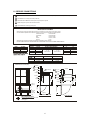
1
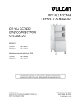
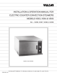
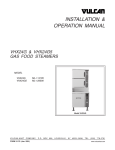
SB-6G, SB-10G and SB-16G
CONVECTION STEAMER ON A GAS FIRED BOILER BASE
INSTALLATION – OPERATION – MAINTENANCE
BLODGETT OVEN COMPANY
www.blodgett.com
44 Lakeside Avenue, Burlington, Vermont 05401 USA Telephone: (802) 658-6600 Fax: (802) 864-0183
1 D (4/09)
S00046 Rev
IMPORTANT NOTES FOR INSTALLATION AND OPERATION
It is recommended that this manual be read thoroughly and that all instructions be
followed carefully.
This is the safety alert symbol. It is used to alert you to
potential personal injury hazards. Obey all safety messages
that follow this symbol to avoid possible injury or death.
WARNING: Improper installation, operation, adjustment,
alteration, service or maintenance can cause property damage,
injury or death. Read the installation, operating and
maintenance instructions thoroughly before installing,
operating or servicing this equipment.
This manual should be retained for future reference.
FOR YOUR SAFETY: Do not store or use gasoline or other
flammable vapors or liquids in the vicinity of this or any other
appliance.
Intended for commercial use only. Not for household use.
PURCHASER: Instructions to be followed in the event that the operator of
this appliance smells gas must be posted in a prominent location. This
information shall be obtained by consulting the local gas supplier.
Keep the appliance area free and clear from combustibles.
Do not obstruct the flow of combustion and ventilation air.
Adequate clearances must be maintained for servicing and proper
operation.
Do not attempt to operate this unit in the event of a power failure.
NOTICE: Contact the factory, the factory representative or local service
company to perform maintenance and repairs.
2
TABLE OF CONTENTS
DESCRIPTION
PAGE
Important Notes for Installation and Operation ............................................................... 2
1.0 Service Connections ............................................................................................... 4
2.0 Installation Instructions ............................................................................................ 5
3.0 Operation Instructions ......................................................................................... 10
4.0 Operation Instructions for Boilers with CSD-1 Controls ........................................ 12
5.0 Operation Instructions, Cooker Section ............................................................... 15
6.0 Periodic Maintenance .......................................................................................... 17
7.0 Adjustments ........................................................................................................ 19
8.0 Troubleshooting ................................................................................................... 21
9.0 Cooking Chart ........................................................................................................ 24
3
1.0 SERVICE CONNECTIONS
ELECTRICAL CONNECTION: 1/2" conduit connection to controls. 120VAC-60Hz-1PH 2 AMPS per compartment or to be as specified on data plate.
COLD WATER: 3/8" O.D. tubing at 25-50 PSI(170-345 kPa)
S
STEAM TAKE-OFF CONNECTION: 3/4"IPS optional to operate adjacent equipment.
DRAIN: 2"IPS piped to open floor drain. No Solid Connection.
GAS CONNECTION: 3/4"IPS supply line required.
WATER QUALITY STATEMENT
Water quality is the major factor affecting the performance of your appliance. If you are unsure of water quality, consult a
local water treatment specialist and have the water analyzed. Your water supply must be within these general guidelines:
Total dissolved solids
Less than 60 PPM
Total alkalinity
Less than 20 PPM
Silica
Less than 13 PPM
Chlorine
Less than 1.5 PPM
pH Factor
7.0-8.5
Water which fails to meet these standards should be treated by installation of water conditioner.
FAILURE OR MALFUNCTION OF THIS APPLIANCE DUE TO POOR WATER QUALITY IS NOT COVERED UNDER WARRANTY.
MODEL
SB-6G
SB-10G
SB-16G
STD INPUT
140,000
200,000
300,000
BTU/HOUR
140,000
200,000
250,000
300,000
kW/HOUR
41.0
58.6
73.3
87.9
GAS SUPPLY
WATER COLUMN PRESSURES
NATURAL
PROPANE
7" - 14"
[178mm-355mm]
11" - 14"
[279mm-355mm]
AVAILABLE CABINET WIDTH
36"
24"
YES
YES
YES
YES
YES
NO
YES
NO
DIMENSIONS
A
55.5 [1410]
68.5 [1740]
67 [1702]
SB-6G
SB-10G
SB-16G
C
14.75 [375]
14.75 [375]
13.5 [343]
B
12.5 [318]
12.5 [318]
6 [152]
DIMENSIONS ARE IN INCHES [MM]
2.75 [70]
S 5.75 [146]
S 36” cabinet
6.25 [159]
6.75 [171]
0 [0]
2.5 [64]
S 8 [203]
0 [0]
2.5 [64]
8 [203]
10 [254]
3.5 [76]
3.5 [89]
26.75 [679]
B
8.75 [222]
6 [152]
5.75 [146]
0 [0]
2916.75 [756]
C
16.75 [425]
28 [711]
24 [610]
24 [610]
SB-6G and SB-10G TOP VIEW
REAR FLANGED FOOT DETAIL
2 EQUALLY SPACED Ø7/16" [11mm] HOLES
ON 2.5 [63] B.C.
4
SB-16G TOP VIEW
33 [838]
25 [635]
3 [76]
3.5 [89]
33 [838]
9.5 [241]
S
36 [914]
24.75 [629]
A
GENERAL
The gas boiler is designed to ASME Code and approved as a steam heating boiler
restricted to operation at pressure not to exceed 15 psi. The gas boiler may be
operational on Natural or Propane gas. Boilers have electronic ignition and may have
optional CSD1 controls.
2.0 INSTALLATION INSTRUCTIONS
UNPACKING
Immediately after unpacking, check for possible shipping damage. If the appliance is
found to be damaged, save the packaging material and contact the carrier within 15
days of delivery.
Before installing, verify that the gas (natural or propane), the elevation from sea level
and the electrical supply agree with the specification on the data plate. NOTE: If this
appliance is being installed above 2000 feet altitude, contact your authorized service
office to assure that the proper orifice size for your elevation has been installed.
LOCATION
The installation location must be kept free and clear of combustibles. Do not obstruct
the flow of combustion and ventilation air. Clearance from combustible construction
must be a minimum of 3 inches from the sides and 6 inches from the back. The
appliance should be installed on a noncombustible floor. Provide adequate clearances
for cleaning, maintenance, service and proper operation.
Sufficient air should be allowed to enter the room to compensate for the amount of air
removed by any ventilating system and for combustion for the gas burners. Do not
obstruct the air flow into and around the appliance. Do not obstruct the flow of flue
gases from the flue duct located at the rear and above the cabinet. Position the
appliance in its final location. Check that there are sufficient clearances to service the
controls, for door swings, etc., so there will be no problem in making the required supply
and drain connections.
Allow enough space between any other piece of equipment or a wall for service access.
Service on the cabinet base may require access to the left and/or right side panels.
5
LEVELING AND ANCHORING THE APPLIANCE
1. Place appliance in the installation position.
2. Place a carpenter’s level on top of the appliance and turn the adjustable feet to level
side-to-side and front-to-back.
3. Mark hole locations on the floor through the anchoring holes provided in the rear
flanged adjustable feet.
4. Remove appliance from installation position and drill holes in locations marked on
the floor. Insert proper anchoring devices (not supplied).
5. Place appliance back in the installation position.
6. Place carpenter’s level on top of appliance and re-level side-to-side and front-toback.
7. Bolt and anchor appliance securely to the floor.
8. Seal bolts and flanged feet with silastic or equivalent compound.
INSTALLATION CODES AND STANDARDS
Gas installation to conform to local codes, or in absence of local codes, with the National
Fuel Gas Code - ANSI Z223.1/NFPA 54, or the Natural Gas and Propane Installation
Code, CSA B149.1, as applicable, including:
1. The appliance and its individual shut off valve must be disconnected from the gas
supply piping system during any pressure testing of that system at pressures in
excess of ½ psig (3.5 kPa).
2. The appliance must be isolated from the gas supply piping system by closing its
individual manual shut off valve during any pressure testing of the gas supply piping
system at test pressures equal to or less than ½ psig (3.5 kPa).
Electrical grounding must be provided in accordance with local codes, or in the absence
of local codes, with the National Electrical Code ANSI/NFPA 70. In Canada, installation
must be in accordance with the Canadian Electrical Code CSA C22.2.
6
WIRING DIAGRAM FOR APPLIANCE IS LOCATED INSIDE CABINET DOOR.
EXHAUST FANS AND CANOPIES
Canopies are set over ranges, ovens, kettles, etc., for ventilation purposes. It is
recommended that a canopy extend 6" past the appliance and be located 6 feet 6 inches
from the floor. Filters should be installed at an angle of 45 degrees or more with the
horizontal. This position prevents dripping of grease and facilitates collecting the run-off
grease in a drip pan, usually installed with the filter. A strong exhaust fan tends to create
a vacuum in the room and may interfere with burner performance or may extinguish pilot
flames. Makeup air openings approximately equal to the fan area will relieve such
vacuum. In case of unsatisfactory performance on any appliance, check with the
exhaust fan in the “OFF” position.
SERVICE CONNECTIONS
NOTICE: If this equipment is being installed at over 2,000 feet
altitude and was not so specified on order, contact service
department. Failure to install with proper orifice sizing may void the
warranty.
PLUMBING CONNECTIONS
WARNING: Plumbing connections must comply with applicable
sanitary, safety, and plumbing codes.
WATER SUPPLY CONNECTION
The incoming cold water supply connection, at the rear of the steamer cabinet, requires
3/8" tubing and water pressure of 25 - 50 psi. A manual shut-off valve must be provided
convenient to the appliance; this valve should be open when the boiler is in operation.
FAILURE OR MALFUNCTION OF THIS APPLIANCE DUE TO POOR WATER
QUALITY IS NOT COVERED UNDER WARRANTY. SEE WATER QUALITY
STATEMENT (PAGE 4)
DRAIN CONNECTION
The steamer drain (2" IPS) should be piped to a floor drain near the steamer. There
should be no solid drain connection; an “open gap” between the steamer and the floor
drain is required.
7
GAS CONNECTION
1. The data plate on the cabinet door of the boiler indicates the type of gas your unit is
equipped to burn. DO NOT connect to any other gas type.
Keep the appliance area free and clear from combustible substances. Do not
obstruct the flow of combustion and ventilation air.
2.
A 3/4" NPT line is provided at the rear for the connection. Each boiler is equipped
with an internal pressure regulator which is set at 3.5" W.C. manifold pressure for
natural gas or 10.5" W.C. for L.P. gas. Use the 1/8" pipe tap on the burner manifold
for checking pressure.
An adequate gas supply is necessary. Undersized or low pressure lines will restrict the
volume of gas required for satisfactory performance. A steady supply pressure, between
7" W.C. and 14" W.C. for natural gas and 11" W.C. and 14" W.C. for propane gas is
recommended. With all units operating simultaneously, the manifold pressure on all
units should not show any appreciable drop. Fluctuations of more than 25% on natural
gas, and 10% on propane gas, will create pilot problems and affect burner operating
characteristics. Contact your gas company for correct supply line sizes.
Purge the supply line to clean out any dust, dirt, or foreign matter before connecting the
line to the unit.
CAUTION: The pipe thread compound used when installing
pipes must be a type that is resistant to the action of liquified
petroleum or propane gases.
Codes require that a gas shut-off valve be installed in the gas line prior to the steamer.
Make sure the pipes are clean and free of obstructions, dirt, and piping compound.
NOTICE: If applicable, the vent line from the gas appliance pressure regulator shall be
installed to the outdoors in accordance with local codes or, in the absence of local
codes, with the National Fuel Gas Code, ANSI Z223.1/NFPA 54, or the Natural Gas and
Propane Installation Code CSA B149.1, as applicable.
WARNING: Prior to start-up, check all joints in the gas supply
line for leaks. Use soap and water solution. Do not use an
open flame.
8
ELECTRICAL CONNECTIONS
WARNING: Electrical and grounding connections must comply with the applicable
portions of the National Electrical Code and/or other local codes.
120 VAC-60 Hz - Single Phase
Make electrical connection to terminal block in rear of unit. A separate 15 amp supply is
needed for each unit.
Refer to the electrical diagram located inside cabinet on door.
9
3.0 OPERATION INSTRUCTIONS
WARNING: Do not force the gas control knob. Use only your hand to turn the gas
control knob. Never use any tool. If the gas control knob will not operate by hand
the gas control should be replaced by a qualified service technician.
WARNING: Do not disassemble the gas control; it contains no replaceable
components. Attempted disassembly or repair may damage the gas control.
WARNING: In the event of main burner ignition failure, a 5 minute purge period
must be observed prior to re-establishing ignition source.
For CSD-1 equipped boilers, see section 4.0 for Operation Instructions for CSD-1
Equipped Boiler.
BOILER CONTROLS (Inside Cabinet)
Main Power Switch
Pilot Light
-
ON fills the boiler tank and turns the boiler controls on.
You should allow 20 minutes to fill the tank and generate
steam.
-
OFF shuts off the boiler controls and opens the automatic
blowdown valve, emptying the boiler tank and releasing
water and steam to the drain. This should be done at least
once daily to remove sediment, lime, or scale.
-
Indicates main power is ON.
Boiler Pressure Gauge -
Should read 9 -11 psi during operation; 0 psi during
shutdown.
Water Level Sight Glass -
Observe level of water in the boiler and water quality.
Murkiness in the water indicates inadequate water quality;
the owner must supply proper water to the boiler (see page
4, Water Quality Statement).
Water Level Control
-
While ON, briefly open the water level control daily to
remove any sediment that might accumulate.
Safety
-
This valve will release (pop off) if the boiler has too much
pressure. Once a week, this valve should be tripped
during operation to make sure it functions properly.
CAUTION: If you smell gas during the lighting procedure, immediately shut off the
gas supply until the leak has been corrected.
10
1. START-UP - BOILER OPERATION WITH STANDING PILOT IGNITION
Open manual gas shut off supply valve and if the appliance has a manual blowdown
valve, close it. Open cabinet door and turn ON power switch located on left side. Green
pilot light will come on, water will begin to enter boiler and required water level will be
reached in about three minutes. Observe water gauge glass to verify.
The dial on the combination gas control valve has three positions (ON-PILOT-OFF) for
manual gas control of main burners and pilot. Turn DIAL to PILOT. Depress dial and
light burner located on centre main burner of boiler. Maintain dial in depressed position
for about 30 seconds and release. Observe that the pilot burner flame stays on. If at
any time the flame should become extinguished, a 5 minute period of complete shut off
of gas supply is required before relighting.
Turn dial to ON and burners should ignite. Steam generation will now commence and
be completed in approximately 15 minutes. Steam generation should reach
approximately 11 psi as indicated on the pressure gauge on the boiler.
2. START UP - BOILER OPERATION WITH ELECTRONIC IGNITION
Open manual gas supply valve.
Open cabinet door and turn main power switch ON. Green pilot light will come on, water
will begin to enter boiler and required water level will be reached in about three minutes.
Observe water gauge sight glass to verify.
11
4.0 OPERATION INSTRUCTIONS FOR BOILERS WITH CSD-1 CONTROLS
WARNING: In the event of main burner ignition failure, a 5 minute purge period
must be observed prior to re-establishing ignition source.
INITIAL START-UP PROCEDURE
1.
Open the manual gas shut-off supply valve.
2.
Close the manual blowdown valve, if so equipped.
3.
Light the pilot burner.
The dial on the gas combination valve has three positions (ON - OFF - PILOT) for
manual gas control of main burners and pilot burner. Turn the dial on the gas
combination valve to “PILOT”, depress the dial and light the pilot burner on the
centre burner. Maintain the dial in depressed position for about 30 seconds and
release. Observe the pilot flame stays ON. Turn dial to “ON”.
If at any time the flame should become extinguished, a five (5) minute purging is
required before relighting is attempted.
4.
Open cabinet door and turn “ON” the power switch.
The green pilot light will come “ON”. Water should begin to enter the boiler. When
enough water has entered the boiler the (amber) “STANDBY” pilot light will come
on.
5.
Press the “RESET” switch to begin boiler operation.
The “STANDBY” pilot light will go off and the boiler will begin operation.
12
4.0 OPERATION INSTRUCTION FOR BOILERS WITH CSD-1 CONTROLS
(Continued)
Daily Startup Procedure
1.
Close the manual blowdown valve, if so equipped.
2.
Examine that the pilot burner flame is burning. If the pilot burner is out, a five (5)
minute period of complete gas supply shut off is required before relighting.
3.
Open cabinet door and turn “ON” the power switch.
The green pilot light will come “ON”. Water will begin to enter the boiler. When
enough water has entered the boiler the (amber) “STANDBY” pilot light will come
on.
4.
Press the “RESET” switch to begin the boiler operation. The “STANDBY” pilot light
will go off and the boiler will begin operation.
Daily Shutdown Procedure
1.
Turn “OFF” the power switch. Observe that the burners go off.
2.
Open the manual blowdown valve, if so equipped. If the appliance is equipped with
an automatic blowdown solenoid valve, the boiler’s contents, water and steam will
be blown out and exhausted through the appliance drain. The cold water solenoid
valve will be activated.
Complete Shutdown Procedure
If the appliance is not intended to be operational for a lengthy period, then shut it down
completely.
1.
Open the manual blowdown valve, if so equipped.
2.
Shut off all supplies of power, gas and water to the appliance.
Normal Boiler Operating Cycle
Water Fill Cycle
On the initial filling of the boiler, the reset switch must be activated to initialize the safety
lockout circuit. Once the water in the boiler has reached the proper level, the level
control will open the circuit to the fill solenoid valve, stopping the flow of water to the
boiler. As the water is consumed in the production of steam, the level control will close
the circuit to the fill solenoid and water will be supplied to the boiler.
13
4.0 OPERATION INSTRUCTION FOR BOILERS WITH CSD-1 CONTROLS
(Continued)
Firing Cycle
The gas valve is operated by pressure sensing devices. On the initial operation of the
boiler, steam generation should reach 11 psi in approximately 15 minutes. At this point
the “Operating Pressure” switch will open, closing the gas valve. When pressure drops
to 9 psi, the pressure switch closes, the gas valve will open and ignition should occur.
Should the pressure rise more than 14.5 psi the “Override Pressure Switch” will close
the circuit to the override solenoid valve, releasing excess steam.
Condensing Drain
A thermostat is located in the drain assembly and is activated by the temperature of
steam. The thermostat opens the cooling solenoid valve, in turn supplying water to the
drain to condense steam.
Automatic Blowdown Valve
If the unit has an automatic blowdown valve, it is activated by the main power switch.
The boiler will be drained should the main power switch be turned “OFF”.
SAFETY LOCKOUT CONDITIONS
High Temperature Condition
A high temperature safety device is installed on the boiler. Should the temperature
exceed the limit of this device, the boiler will be shut down and put in a state of lockout.
The “Temperature” pilot light (red), and the “Standby” pilot (amber), will come on.
High Pressure Condition
A high pressure safety switch is installed on the boiler. Should the pressure exceed the
limit of this device, the boiler will be shut down and put into a state of lockout. The
“Pressure” pilot light (red), and the standby pilot light (amber), will come on. Should this
device fail to operate, the safety relief valve will open.
Low Water Condition
A second low water safety cut off is supplied with the boiler. Should the water level fall
below normal operating levels, this device will shut down and put the boiler in a state of
lockout. The “Low Water” pilot light (red), and the “Standby” pilot light (amber) will come
on.
14
5.0 OPERATION INSTRUCTIONS
COOKER SECTION
CAUTION: Live steam and accumulated hot water in the compartment may be
released when the door is opened.
Start-up procedures for your cooker must be completed once daily prior to operation
(see instruction plate or previous section in this manual for boiler start up procedures).
With ready pilot light on, preheat cooker compartment for one minute when the cooker is
to be first used for the day or whenever the compartment is cold.
1.
Close compartment doors and set timer to “1 minute”.
2.
When buzzer sounds, set timer to the “OFF” position.
3.
Cooker is now ready for cooking.
4.
With cooking compartment preheated and ready pilot light on, place pans of food to
be cooked into compartment and shut door.
5.
Set timer to cooking time desired. Cooking cycle may be interrupted at any time by
opening door and resumed again by closing door.
6.
When buzzer sounds, it indicates the end of the cooking cycle and that no more
steam is entering the compartment. Cooking pilot light will go off and ready pilot
light will come on. Buzzer must be shut off by turning the timer to its off position.
CAUTION: An obstructed drain can cause personal injury or property damage.
Frequently check that the compartment drain and plumbing are free of all obstructions.
Never place food containers, food or food portion bags in the cooking compartment in
such a way that the compartment drain becomes obstructed.
Each compartment is equipped with a removable drain screen. Frequently check the
drain screen for accumulation of food particles. Should food particles accumulate
against, or clog the drain screen, remove it, clean it thoroughly and then replace it in its
original position.
15
COOKER SECTION (Continued)
SHUTDOWN
a)
To shut down cooking compartment, set timers to their OFF position and leave
doors slightly open.
b)
At the end of the day, the steam supply must be shut off. Details are on boiler
instruction plate or previous section of this manual.
WARNING: Never spray water into electric controls.
NOTICE: Contact the factory, the factory representative or a local service company to perform
maintenance and repairs should the appliance malfunction. Refer to warranty terms.
16
6.0 PERIODIC MAINTENANCE
WARNING: Disconnect the unit from the power supply before cleaning or
servicing appliance.
IMPORTANT INSTRUCTIONS
Be sure to flush your boiler water level control daily. Failure to follow this procedure can
cause the control to malfunction resulting in serious boiler damage.
The Boiler Water Level Control installed on your boiler requires periodic maintenance.
As boiler water circulates into the float chamber, sand, scale and other sediment may be
deposited in the float chamber. While the chamber has been designed with a large
accumulation bowl, it is necessary to flush the sediment from the chamber by blowing
down the control so that the accumulation of sediment does not interfere with the
movement of the float in the control. Control must be flushed at least once a day.
17
IMPORTANT INSTRUCTIONS (Continued)
CAUTION: Protect yourself. When flushing control, hot water and steam will flow
out of the drain.
When flushing control, note water level in gauge glass, allow the boiler to fill if
necessary, and also to come up to temperature.
Before flushing control, note that water level in gauge glass is within operating range and
the boiler pressure is at least 6 psi. While the boiler is being fired, open blowdown valve
at bottom of control by rotating the handle counterclockwise about 1/4 turn to fully open
the valve. Opening the blowdown valve also checks the cut-off operation. Float should
drop shutting burners off, hot water and steam will flow out the drain flushing away
sediment.
CAUTION: If burner does not shut off during blowdown, immediately discontinue
use of appliance and call for service.
Continue draining water for about fifteen (15) seconds, from control until water is clean.
Manually close valve. Recheck gauge glass. If water level has dropped significantly,
wait for the boiler to restore water level and pressure and repeat if necessary.
CLEANING
CAUTION: Do not use cleaning agents that are corrosive.
1. Keep exposed cleanable areas of unit clean at all times.
2. Thoroughly wash oven cavities, door liners, and pan racks at the end of each day, or
as required, with a mild detergent and water to prevent bacterial growth and odours.
3. Remove drain screens from inside compartment drains. Using a plastic bottle brush
and mild detergent, clean inside the drain opening ensuring there is no food residue
or blockage. Clean the drain screen and replace in its original position.
4. Wash gasket sealing surface daily with mild detergent to remove harmful food acids.
5. Clean around burner air mixer and orifice if lint has accumulated.
6. Visually assure carry over ports are unobstructed.
18
7. Rinse entire unit and dry. DO NOT GET WATER in electrical box or any electrical
component.
7.0 ADJUSTMENTS
At least twice a year have an authorized service person clean and adjust the unit for
maximum performance.
BOILER DESCALING INSTRUCTIONS
It is recommended that the boiler should be checked every 90 to 120 days for scale build
up. Regular maintenance should be carried out at this time.
If the boiler has been descaled, a new Anode should be installed in the boiler to help
extend its life.
1.
With boiler empty, close manual blowdown valve. If appliance is equipped with
automatic blowdown, turn water supply OFF to appliance. Turn power switch ON.
This will energize and close blowdown valve.
2.
Remove 3/4" pipe plug from fitting on left front of boiler.
3.
Insert appropriate hose or tube through fitting and pour in (½) half gallon (U.S.) of
CLR Descaling Solution or use the Optional Deliming Assembly DPA-1 available
from your dealer.
For appliances equipped with CSD-1, descaling solution must be introduced
through hand hole.
4.
Replace 3/4" pipe plug securely.
5.
Open water supply to appliance allowing water to fill boiler to required level.
6.
Let appliance cycle, allow two hours for descaling and cleaning. DO NOT TURN
STEAM ON TO THE COMPARTMENTS.
7.
Open both the blowdown and low water level control valves for complete drainage
and then close both valves.
Appliance equipped with automatic blowdown - turn OFF power switch and open
low water control valve. This will allow complete drainage. Once drained close
water level control valve.
8.
Turn appliance switch ON. When boiler is completely filled, turn power switch OFF.
This will rinse and drain boiler. Appliance with manual blowdown valve must be
opened to drain.
9.
Complete Step 8 twice to assure boiler is completely rinsed.
19
10. Appliance is now ready for use.
TO CALIBRATE PRESSURE SWITCHES
NOTE: Pressure switches are factory set. Calibration is only required if pressure switches are
replaced or if adjustment is required.
Pressure switch range is from 1 to 15 psi.
Adjust all settings to maximum on high signal adjustment screw on pressure switches.
Adjust in the following sequence:
- High limit pressure switch.
- Override pressure switch.
- Operating pressure switch.
- Turning screw clockwise to increase, counterclockwise to decrease pressure.
- Use relief valve to release pressure from boiler for setting adjustments.
1. HIGH LIMIT PRESSURE SWITCHES
Allow pressure to build until unit shuts off. This should occur at 15 psi. Set the high
signal to switch at 14.5 psi on the gauge and the low signal to 13.0 psi.
2. OVERRIDE PRESSURE SWITCHES
Allow pressure to increase to 13 psi. Set the high signal to switch at 13 psi on the
gauge and the low signal to 11 psi.
3. OPERATING PRESSURE SWITCHES
Set the high signal to switch at 11 psi on the gauge and the low signal to 9 psi.
4. Release pressure in boiler to below 9 psi. Burner will come on. Once pressure has
reached 11 psi, burners will shut off. Repeat this process several times to make sure
burners come on at 9 psi and shut off at 11 psi.
20
TO CALIBRATE PRESSURE SWITCHES (Continued)
Once completed, pressure switches have been calibrated.
Should your unit not have the High Limit pressure switch, start procedure at Override
pressure switch.
SERVICE
Contact your local authorized service office for any repairs or adjustments needed on
this equipment.
NOTICE: Contact the factory, the factory representative or local service company to
perform maintenance and repairs.
21
8.0 TROUBLESHOOTING
DOOR LEAKS
1. Check for damage to door gasket.
2. Compartment drain opening or associated piping may be blocked.
WATER ACCUMULATES IN THE COMPARTMENT
1. Compartment drain screen clogged. Remove and clean thoroughly and replace.
WATER NOT BEING SUPPLIED TO BOILER
1. Water supply is “OFF”.
2. Defective water fill solenoid valve.
3. Water level control clogged or defective, unable to operate fill valve.
4. Check drain valve is closed. Also check that water level control valve is closed.
5. Supply water pressure too low.
AUTOMATIC BLOWDOWN VALVE DOES NOT DRAIN
1. Defective blowdown valve.
2. Heat exchanger build up of scalant clogging drain lines and valve.
BOILER ACHIEVES PRESSURE SLOWER THAN NORMAL
1. Heavy build up of lime or scalant hampering heat transfer. Call for service to inspect
interior of boiler. Should a considerable amount of scalant be found, have steam
lines, water level control and valve also inspected.
SAFETY VALVE BLOWS
1. Defective safety valve.
2. Pressure too high. Pressure switch requires adjustment (lower) or may be defective.
22
BURNERS PRODUCE CARBON DEPOSITS
1. Wrong size orifices.
2. Burner air not adjusted properly.
3. Wrong gas supply.
4. Incorrect pressure at supply.
BURNERS DO NOT COME ON
1. Gas supply to unit is “OFF”.
2. Manual shut off valve is “OFF”.
3. Pilot is out.
4. Power supply is “OFF”.
5. Water level has not been reached. Check water supply and water level control.
6. Pilot may require flame adjustment on option electronic ignition units.
7. If water at proper level, check relay which energizes pressure switch and gas valve.
8. Pressure switch may need to be replaced if relay is operating.
9. Check gas control. If energized but not operating, have replaced.
PILOT LIGHT DOES NOT IGNITE (ELECTRONIC IGNITION)
1. Gas control knob is in “OFF” position.
2. Loose or dirty wire connection to ignition module, clean/or tighten.
3. Ignition cable shorting out. Check that it is not in contact with metal or damaged.
4. Defective ignition module.
5. Unit is 100% lock out. Turn off and try in five minutes.
6. Dirty flame sensor. Clean with emery cloth.
7. Pilot burner/ignitor sensor, cracked ceramic insulator. Have replaced.
8. Check for too much draft in room.
23
9.0 COOKING CHART
The following table lists suggested cooking times and weights. These times, which will
vary depending on initial product temperature, size, shape, etc., are approximate and
should be adjusted to suit your operation.
PRODUCTS TO BE COOKED IN SOLID PANS
Product
Eggs, Scrambled
Rice, Long Grain (Cover with 4 cups water/lb)
Timer Setting
in Minutes
Weight Per
Pan
10 - 12
8 Dozen
25
2 Lb
Pasta
(Place perforated pan inside solid pan, cover pasta with cold
water)
Spaghetti - Regular/Vermicelli
12 - 15
Macaroni - Shells/Elbows
15 - 18
Noodles - ½" Wide
12 - 15
Lasagna Noodles
15 - 18
Frozen Casseroles, Lasagna
35
Full Pan
Meat Loaf, 3 - 5 Lb Each
40
15 Lb
Ground Chuck
20 - 25
10 Lb
Slices as Purchased
35 - 40
10 Lb
5
4 Lb
Baked
9
10 Lb Can
Refried
9
10 Lb Can
6
10 Lb Can
Beef
Shrimp, Frozen, 10 Shrimp per Lb
Beans
Canned Vegetables
Prunes, Dried
12 - 15
24
PRODUCTS TO BE COOKED IN PERFORATED PANS
Timer Setting
in Minutes
Weight Per
Pan
10 - 12
3 Dozen
5-6
3 Dozen
Claws
4
2 ½ Lb
Legs
4-6
4 ½ Lb
Lobster Tail, Frozen
6
10 Lb
Lobster, Live, 10" - 12"
5
4 Per Pan
Salmon Fillets, Frozen, 8 oz Each
5
7 ½ Lb
Scallops, Fresh
4
3 Lb
3-5
4 Lb
Hard Cooked
15
4 Dozen
Soft Cooked
9 - 10
4 Dozen
Soft Yolk for Caesar Salad
6-8
4 Dozen
20
15 Lb
Breasts (2)
90
6 - 7 Lb Ea.
Cut length wise
55
20 - 25 Lb
40 - 75
6 - 8 Lb
3
80 - 100 Count
Frozen
10 - 12
3 Dozen
Fresh
5
5 Lb
Green, 2" Cut, Frozen/Fresh
6
5 Lb
Lima, Frozen
8
5 Lb
Baby Lima, Frozen
5
5 Lb
Spears, Frozen
8
4 Lb
Spears, Fresh
6
5 Lb
Flowerettes, Frozen
6
5 Lb
Product
Clams
Frozen
Fresh, Cherrystone
King Crab, Frozen
Scrod Fillets, Fresh
Eggs
Chicken, Breasts, Legs, Thighs
Turkey, Frozen
Corned Beef
Hot Dogs or Wieners
Asparagus Spears
Beans
Broccoli
25
PRODUCTS TO BE COOKED IN PERFORATED PANS
Timer Setting
in Minutes
Weight Per
Pan
Brussel Sprouts, Frozen
6
5 Lb
Cabbage, Fresh, 1/6 Cut
8
5 Lb
Baby Whole, Frozen
8
7 Lb
Crinkle Cut, Frozen
7-8
4 Lb
11
9 Lb
Frozen
6
4 Lb
Fresh
7-8
5 Lb
7
5 Lb
Yellow Whole Kernel, Frozen
5
5 Lb
Cobbettes, Frozen
8
27 Ears
16-18
80 Ears
10-12
18 Ears
16-18
54 Ears
Peas, Green
6
5 Lb
Potatoes, Whole Russet
55
10 Lb
Chopped, Frozen
17
6 Lb
Defrosted
5
6 Lb
Fresh Cut
3
2 Lb
Squash, Acorn, Halves
25
10 Halves
Zucchini, Slices
8
10 Lb
6-7
5 Lb
Product
Carrots
Sliced, Fresh
Cauliflower, Flowerettes
Celery, 1" Diagonal Cut
Corn
Corn-On-Cob, Fresh
Spinach
Frozen Mixed Vegetables
Fruit, Blanch for Peeling
3
Grapefruit
Oranges
Pineapple, Whole for Cutting
4
COOKING HINTS
Where possible, spread food out evenly in pans. Do not allow food to protrude above
pans, since this will interfere with steam circulation between pans in the compartment.
Always preheat compartments for satisfactory results. When time does not allow for
defrosting of frozen vegetables, such as loose-pack peas, corn diced carrots, etc., they
may be cooked at once provided just half of the suggested portions in the cooking chart
are used.
26