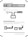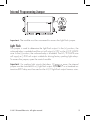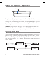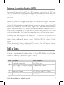
1
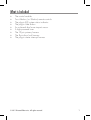
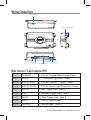
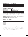
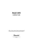
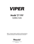
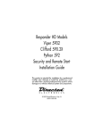
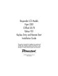
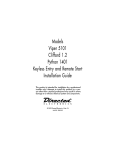
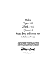
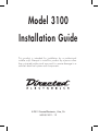
Model 3100
Installation Guide
This product is intended for installation by a professional
installer only! Attempts to install this product by a person other
than a trained professional may result in severe damage to a
vehicle’s electrical system and components.
© 2011 Directed Electronics, Vista, CA
N3100 2011 - 12
Contents
What is Included.................................................................................................. 1
Wiring Connections.............................................................................................. 2
Main Harness 12-pin Connector (H1)...................................................... 2
Door Lock, 3-Pin Connector (H2)............................................................. 3
Horn Honk, 3-pin connector................................................................... 3
Starter Interrupt Harness (H3) ................................................................ 4
Plug-in LED and Valet Program switch...................................................... 4
Internal Programming Jumper .............................................................................. 5
Light Flash............................................................................................ 5
Onboard Dual Stage Zone 2 Impact Sensor........................................................... 6
Bypassing Sensor Inputs........................................................................................ 6
Nuisance Prevention Circuitry (NPC)...................................................................... 7
Table of Zones...................................................................................................... 7
Remote Control Programming............................................................................... 8
Function Table...................................................................................... 9
System Feature Programming................................................................................ 9
Feature Table..................................................................................... 10
Feature Descriptions............................................................................ 11
Troubleshooting.................................................................................................. 13
What is Included
•
•
•
•
•
•
•
•
•
The control module
Two 4-button, (or 3-button) remote controls
The plug-in LED system status indicator
The plug-in Valet button
An on-board dual zone impact sensor
A high-powered siren
The 12-pin primary harness
The 3-pin door lock harness
The plug-in starter interrupt harness
© 2011 Directed Electronics. All rights reserved.
1
Wiring Connections
Impact sensor adjuster
Starter interrupt input/output
Door Lock port
3-pin Horn Honk Harness
Status LED port
12-pin Primary Harness
Valet button port
Main Harness 12-pin Connector (H1)
2
H1/1
ORANGE
(-) 500 mA Ground-When-Armed Output
H1/2
WHITE
(+/-) Selectable Light Flash Output
H1/3
WHITE/BLUE
(-) 200 mA Channel 3 Validity Output
H1/4
BLACK/WHITE
(-) 200 mA Interior Light Illumination Output
H1/5
GREEN
(-) Door Trigger Input, Zone 3
H1/6
BLUE
(-) Multiplex Trigger Input, Zone 1
H1/7
VIOLET
(+) Door Trigger Input, Zone 3
H1/8
BLACK
(-) Chassis Ground Input
H1/9
YELLOW
(+) Ignition Input, Zone 5
© 2011 Directed Electronics. All rights reserved.
H1/10
BROWN
(+) Siren Output
H1/11
RED
(+)12 V Constant Power Input
H1/12
RED/WHITE
(-) 200 mA Channel 2 Validity Output
Door Lock, 3-Pin Connector (H2)
1
GREEN
(-) Lock, (+) unlock output
2
OPEN
except if using 451M
3
BLUE
(+) Lock, (-) unlock output
This security system can control two common power door lock types without
any additional parts. With certain vehicles, or if an actuator is to be installed,
either a 451M Door Lock Relay Satellite or two relays will be required.
Important: For additional Door Lock information refer to Tech tip #1041 at
www.directechs.com or contact your local distributor.
Horn Honk, 3-pin connector
H/1
OPEN
NO FUNCTION
H/2
BROWN/BLACK
(-) 200 mA HORN HONK OUTPUT
H/3
OPEN
NO FUNCTION
This wire outputs a single pulse when arming the system and two pulses when disarming the system. This wire will also output pulses for 30
seconds when the system is triggered or if panic mode is activated. If
the vehicle has a (+) horn circuit, a standard automotive SPDT relay or
a relay assembly package (p/n 8617) must be used.
© 2011 Directed Electronics. All rights reserved.
3
Starter Interrupt Harness (H3)
1
BLACK
Starter interrupt input
2
BLACK
Starter interrupt output
Use one of these wires as a starter interrupt input and the other as a starter
interrupt output wire
Important: These two black wires are interchangeable.
Control Module
Plug-in LED and Valet Program switch
These plug into the control module. The status LED plugs into the white 2-pin
socket, while the valet program switch plugs into the blue 2-pin connector. The
status LED and valet switch each fit into a 9/32 inch hole.
Valet Program
button
LED
Blue 2-pin port
White 2-pin port
4
Control
Module
© 2011 Directed Electronics. All rights reserved.
Internal Programming Jumper
Important: The module must be unscrewed to access the light flash jumper.
Light Flash
This jumper is used to determine the light flash output. In the (+) position, the
on-board relay is enabled and the unit will output (+)12V on the H1/2 WHITE
wire. In the (-) position, the on-board relay is disabled. The H1/2 WHITE wire
will supply a (-) 200 mA output suitable for driving factory parking light relays.
To access the jumper, open the control module.
Important: For parking light circuits that draw 10 amps or more, the internal
jumper must be switched to a (-) light flash output. P/N 8617 or a standard automotive SPDT relay must be used on the H1/2 light flash output harness wire.
© 2011 Directed Electronics. All rights reserved.
5
Onboard Dual Stage Zone 2 Impact Sensor
Impact sensor adjuster
There is a dual-stage impact sensor inside the control unit. Adjustments are
made via the rotary control as indicated above. Since the impact sensor does
not work well when mounted firmly to metal, we recommend against screwing
down the control module. We recommend mounting the control module to a
large wiring loom.
Important: When adjusting the sensor, it must be mounted in the same location where it will be after the installation is completed. Adjusting the sensor
and then relocating the module requires readjustment.
Bypassing Sensor Inputs
Sensors can be bypassed during auxiliary channel and add-on accessory operations. During an auxiliary channel output apply ground to the H1/6 wire,
the sensors will be bypassed and will not trigger the alarm until several seconds
after the ground ceases. This is ideal for add-on remote starters and window
control modules:
ADD-ON REMOTE
START UNIT
6
© 2011 Directed Electronics. All rights reserved.
Nuisance Prevention Circuitry (NPC)
Nuisance Prevention Circuitry™ or (NPC) bypasses input zones for 60 minutes.This prevents annoying repetive trigger sequence due to faulty door pin
switches or environmental conditions such as thunder, jackhammers, and airport noise.
When the same zone triggers three times, less than an hour apart, the system
bypasses that zone for 60 minutes. If the zone does not trigger the system
during the 60-minute bypass period, zone monitoring begins again when 60
minutes has passed. If the zone does trigger while bypassed the 60-minute
bypass starts over again. The vehicle doors are protected differently by NPC.
If the system is triggered by an open door for three, full 30-second cycles (one
and one half minutes), the system bypasses the doors until the trigger ceases.
Disarming and rearming does not reset NPC. To reset NPC 60-minutes must
pass without a trigger, or it is reset when the ignition is turned on. The system is
able to trigger repeatedly, disarm, re-arm, and allow NPC to bypass a faulty
zone.
When disarming 5 chirps indicates NPC is active. The LED reports the bypassed zone, as described in the table below.
Table of Zones
A zone is represented by the number of status LED flashes used by the
system to identify a particular type of input.
Zone
Description
Input Description
1
(-) multiplex trigger input
H1/6 Blue wire
2
Instant trigger: a heavier impact
detected by the on-board shock
sensor
On-board shock sensor.
3
Door switch trigger
H1/5 Green and H1/7 Violet
5
Ignition trigger
H1/9 Yellow wire
© 2011 Directed Electronics. All rights reserved.
7
Remote Control Programming
Remote controls included in this system are pre-programmed in the standard
button configuration, and are ready to use. This system will accept up to four
remote controls.
To add, delete, or reprogram remote controls with customized button configurations, use the following procedure.
Important: Test the systems Ignition input, Door trigger input, Valet button,
Status LED, and siren for proper operation before proceeding.
1.
2.
3.
4.
5.
Select a System Function and the required number of valet button presses,
as described in the following table. (see Function description table)
Open a door and turn the key ON (run position).
Press and release the Valet button to select the function. After pressing
and releasing corresponding to the function, then press the Valet button
once more and hold it. The LED flashes and the siren sounds to confirm
the selection.
While holding the Valet button, press the remote button that controls the
selected function. The siren emits one long sound to confirm programming.
Release the Valet button to finish and exit programming, or to program
another function return to step 3 and continue through step 5 again (Example: after programming ‘Arm only’, select ‘Panic only’ by pressing and
releasing the Valet button two times, then press and hold it). Repeat to
program more functions.
Exit Programming
The siren emits one quick chirp, and then another lengthier chirp when exiting.
Programming is exited if any of the following occurs:
• Turn ignition off
• Close the doors
• Press Valet button too many times
• 15 seconds or more lapses between steps
8
© 2011 Directed Electronics. All rights reserved.
Function Table
Valet button presses
(Chirps/Flashes)
System Function
1
Arm/Disarm/Panic
2
Aux Channel 2
3
Aux Channel 3
4
Arm only
5
Disarm only
6
Panic only
7
Auto-learn standard configuration*
8
Delete remote controls & Reset features**
*Press any remote button to program the standard button configuration as
described in the owners manual.
** Press any button of a programmed remote to delete all remote controls from
the system and to reset the features to default settings.
System Feature Programming
The system features are pre-programmed to default settings and may need to
be changed to accommodate vehicle specific requirements and user preferences. To change the system feature settings use the following procedure:
Important: Test the systems Ignition input, Door trigger input, Valet button,
Status LED, and siren for proper operation before proceeding.
1.
2.
3.
Select a System Feature and required number of Valet button presses as
described in the following Features table.
Open a door, turn the key ON, and then OFF.
Press and release the Valet button to select the feature. After pressing
and releasing corresponding to the selected function, then press the Valet
button once more and hold it. The LED flashes and the siren sounds to
confirm the selection.
4. While still holding the Valet button press the
© 2011 Directed Electronics. All rights reserved.
button on the
9
AUX
AUX
remote to set the feature to the LED On option. To set the LED
Off, while still holding the Valet button, press
.* (See Feature
Table)
5. Release the Valet button to exit programming, or repeat the above
to program more features.
* Press
or AUX on the 3-button remote to set the feature to
the LED Off option.
AUX
AUX
Exit Programming
The siren emits one quick chirp, and then another lengthier chirp when exiting.
Programming is exited when one of the following occurs:
•
•
•
•
Turn ignition ON
Close the doors
Press Valet button too many times
15 seconds or more lapses between steps
Feature Table
Valet button presses
(Chirps/
Flashes)
10
LED ON OPTION*
1 chirp
LED OFF OPTION
2 chirps
1
Active Arming
Passive Arming
2
Confirmation Chirps ON
Confirmation Chirps OFF
3
Ign-controlled Locking ON
Ign-controlled Locking OFF
4
Active Locking
Passive Locking
5
0.8 Second Doorlock Pulse
3.5 Second Door Lock Pulse
6
Double Pulse Unlock OFF
Double Pulse Unlock ON
7
Code Hopping ON
Code Hopping OFF
8
Door Trigger Error Chirp ON
Door Trigger Error Chirp OFF
9
Double Pulse Lock OFF
Double Pulse Lock ON
© 2011 Directed Electronics. All rights reserved.
10
Comfort Closure OFF
Comfort Closure ON
* Default settings.
Feature Descriptions
1.
Active/Passive Arming
• Active Arming: the transmitter must be used to arm the system.
• Passive Arming: after exiting the vehicle system arms automatically.
Note: Doors must be closed. The system is passively armed 30 seconds
after closing the doors.
2.
Confirmation Chirps:
• ON: arm, disarm, and sensor warn-away chirps are active
• OFF: arm and disarm chirps are defeated, warn-away chirps are
active
Ign-controlled Locking
• ON: the door lock/unlock outputs activate when ignition is turned
on/off.
• OFF: the door lock/unlock outputs do not activate when ignition is
turned on/off.
Note: Doors must be closed for ignition lock to work.
3.
4.
Active/Passive Locking
• Active Locking: The doors do not lock when passively arming only
when using the remote.
• Passive Locking: The doors automatically lock when the system passively arms.
5.
Door Lock Pulse
• 0.8 seconds: the door lock output pulses are 800mS in duration.
• 3.5 seconds: the door lock pulses are 3.5 seconds in duration.
6.
Double Pulse Unlock
© 2011 Directed Electronics. All rights reserved.
11
•
•
OFF: the door unlock output provides a single pulse.
ON: the door unlock output provides a double pulse.
7.
Code Hopping
• ON: The code hopping portion of messages from the remote controls are decrypted before a command is activated
• OFF: The code hopping portion of the remote control messages are
ignored resulting in possible range improvement.
8.
Door Trigger Error Chirp
• ON: If the door trigger is active when arming, the siren emits 1
additional chirp to alert you.
• OFF: An active door trigger when arming does not generate an
alert output.
Double Pulse Lock
• OFF: Lock output provides a single pulse.
• ON: Lock output provides a double pulse.
9.
10. Comfort Closure
• OFF: Comfort Closure is defeated when arming.
• On: 800mS after door lock pulse or 2nd pulse for double setting.
Door lock output turns on again for 20 seconds.
Important: If the unit is disarmed while the 20 second timer is active
when closing the windows, Comfort Closure output immediately stops
before the doors unlock.
The alarm system does not monitor zone inputs for bypass notification,
Warn Away, or full trigger inputs - until the 20 second timer is completed.
This avoids any false system triggering while the windows are in motion.
12
© 2011 Directed Electronics. All rights reserved.
Troubleshooting
•
Door input does not immediately trigger full alarm. Instead, first I hear
chirps for 3 seconds:
That’s how the progressive two-stage door input works! This is a feature of
this system. This is an instant trigger, even if the door is instantly re-closed,
the progression from chirps to constant siren will continue.
•
Closing the door triggers the system, but opening the door does not:
•
System will not passively arm until it is remotely armed and then disarmed:
Have you correctly identified the type of door switch system? This often
happens when the wrong door input has been used.
Are the door inputs connected? Is the H1/6 Blue wire connected to the
door trigger wire in the vehicle? Use the H1/5 Green or the H1/7 violet
wire instead.Door input does not respond with the progressive trigger,
but with immediate full alarm:
Does the LED indicate that the trigger was caused by the impact sensor?
(See Table of Zones section of this guide.) The impact sensor, if set to
extreme sensitivity, may be detecting the door unlatching before the door
switch sends its signal. Reducing the sensitivity can solve this problem.
•
The Valet/Program button does not work:
•
The LED system status indicator does not work:
•
Starter interrupt does not work:
Is it plugged into the correct socket? The button plugs into the Blue 2-pin
port.
Is the LED plugged into the correct socket? The LED plugs into the White
2-pin port.
Is the correct wire being interrupted? If the vehicle starts when the starter
interrupt is disconnected, the wrong wire has been cut.
Is the Yellow H1/9 ignition wire connected to true ignition? Wire must be
powered in the run and start positions in order to work properly.
© 2011 Directed Electronics. All rights reserved.
13
The company behind this system is Directed Electronics
Since its inception, Directed Electronics has had one purpose, to provide consumers with the finest vehicle security and car stereo products and accessories available.
The recipient of nearly 100 patents and Innovation Awards in the field of advanced
electronic technology.
Quality Directed Electronics products are sold and serviced
throughout North America and around the world.
Directed Electronics is committed to delivering world class quality products and services that excite and delight our customers.
Directed Electronics
Vista, CA 92081
www.directed.com
© 2011 Directed Electronics - All rights reserved
N3100 2011-12