1
C H A P T E R
3
I/O Specifications
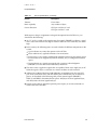
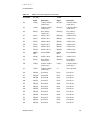
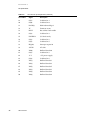
Table 3-2
42
PCI connector pin assignments (continued)
Pin number
Signal
Description
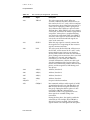
A1
GND
(TRST L)
On the 12” and 7” cards, this pin is connected to
ground. On the PCI bus, it may be used for Test
Reset, which asynchronously initializes the TAP
(Test Access Port) controller.
B2
GND
(TCK)
On the 12” and 7” cards, this pin is connected to
ground. On the PCI bus, it may be used for Test
Clock, which clocks state information and test
data into and out of the PCI card during TAP
operations.
B11
GND
(PRSNT2 L)
On the 12” and 7” cards, this pin is connected to
ground. On the PCI bus, it may be used for
Present 2, which is used in conjunction with
Present 1 (pin B9) to indicate the presence of a
PCI card in the PCI slot and to indicate the power
requirements for the card. In the case of the
12” and 7” cards cards, Present 1 is open and
Present 2 is grounded, indicating the presence of
a PCI card with a 15 W maximum power
requirement.
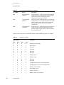
A5, A8, A10,
A16, A59, A61,
A62, B5, B6,
B19, B59, B61,
B62
+5 V
On the 12” and 7” cards, these pins are connected
to +5 V. They are also generally connected to +5
V on the PCI bus.
A3
+5 V
(TMS)
On the 12” and 7” cards, this pin is connected to
+5 V. On the PCI bus, it is used for Test Mode
Select, which controls the state of the TAP
controller.
A4
+5 V
(TDI)
On the 12” card, this pin is connected to +5 V. On
the 7” card it is tied to B4. On the PCI bus, it is
used for Test Data Input, which serially shifts test
data and test instructions into the PCI card
during TAP operations.
A2
+12 V
On the 12” and 7” cards, this pin is connected to
the +12 V power supply. It is also generally
connected to +12 V on the PCI bus.
B1
–12 V
On the 12” and 7” cards, this pin is connected to
the –12 V power supply. It is also generally
connected to –12 V on the PCI bus.
A7
Not connected
(INTC L)
On the 12” and 7” cards, this pin is not
connected. On the PCI bus, it is generally used
for Interrupt C, which requests an interrupt and
is only used on a multifunction device.
A9, A11, A14,
A19, B10, B14
Not connected
(reserved)
On the 12” and 7” cards, these pins are not
connected. On the PCI bus, they are reserved for
future use.
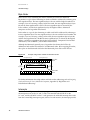
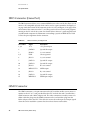
PCI Connector