1
AT85C51SND3B Firmware
..............................................................................................
User’s Guide
Section 1
Introduction ........................................................................................... 1-1
Section 2
Firmware Features................................................................................ 2-3
2.1
MMI Manager ............................................................................................2-3
2.1.1
Features .............................................................................................2-3
2.1.2
Configuration ......................................................................................2-3
2.2
Device USB...............................................................................................2-3
2.2.1
Features .............................................................................................2-3
2.2.2
Configuration ......................................................................................2-4
2.3
Host USB ..................................................................................................2-4
2.3.1
Features .............................................................................................2-4
2.3.2
Configuration ......................................................................................2-4
2.4
Audio Player..............................................................................................2-4
2.4.1
Features .............................................................................................2-4
2.4.2
Configuration ......................................................................................2-5
2.5
Audio Recorder .........................................................................................2-5
2.5.1
Features .............................................................................................2-5
2.5.2
Configuration ......................................................................................2-5
2.6
Image Viewer ............................................................................................2-5
2.6.1
Features .............................................................................................2-5
2.6.2
Configuration ......................................................................................2-5
2.7
Settings .....................................................................................................2-5
2.7.1
Features .............................................................................................2-6
2.7.2
Configuration ......................................................................................2-6
2.8
Update ......................................................................................................2-6
2.8.1
Features .............................................................................................2-6
2.8.2
Configuration ......................................................................................2-6
2.9
File System ...............................................................................................2-6
2.9.1
Features .............................................................................................2-6
2.9.2
Configuration ......................................................................................2-7
2.10 Nand Flash................................................................................................2-7
2.10.1 Features .............................................................................................2-7
2.10.2 Configuration ......................................................................................2-7
2.11 MMC® SD® Cards .....................................................................................2-7
2.11.1 Features .............................................................................................2-7
2.11.2 Configuration ......................................................................................2-8
2.12 Display ......................................................................................................2-8
AT85C51SND3Bx Firmware User’s Guide
1
7691A–MP3–08/07
Table of Contents
2.12.1 Features .............................................................................................2-8
2.12.2 Configuration ......................................................................................2-8
2.13 Keyboard...................................................................................................2-8
2.13.1 Features .............................................................................................2-8
2.13.2 Configuration ......................................................................................2-8
2.14 Power Manager.........................................................................................2-8
2.14.1 Features .............................................................................................2-8
2.14.2 Configuration ......................................................................................2-8
2.15 Clock Manager ..........................................................................................2-9
2.16 System ......................................................................................................2-9
2.16.1 Features .............................................................................................2-9
2.16.2 Configuration ......................................................................................2-9
Section 3
Source Files Organization .................................................................. 3-11
3.1
Directory Physical Structure....................................................................3-11
3.1.1
snd3b-dvk-x_y_z Directory ...............................................................3-11
3.1.2
_isp_modules Directory ....................................................................3-11
3.1.4
drivers Directory ...............................................................................3-12
3.1.5
lib_mcu Directory..............................................................................3-12
3.1.6
lib_mem Directory.............................................................................3-13
3.1.7
lib_system Directory .........................................................................3-13
3.1.8
mmi Directory ...................................................................................3-13
3.1.10 Tools directory ..................................................................................3-14
3.2
Directories Logical Organization .............................................................3-14
Section 4
Code & Data Management ................................................................. 4-15
4.1
Principle ..................................................................................................4-15
4.1.1
Custom memory organisation...........................................................4-15
Section 5
Architecture......................................................................................... 5-21
5.1
5.2
5.3
Overview .................................................................................................5-21
Architecture.............................................................................................5-22
KERNEL..................................................................................................5-23
5.3.2
The Tasks.........................................................................................5-24
5.3.3
The Inter-Task Communication ........................................................5-24
5.3.4
MMI Manager task............................................................................5-26
5.4
MMI Applications.....................................................................................5-28
5.4.1
2
7691A–MP3–08/07
Application IDs..................................................................................5-28
AT85C51SND3Bx Firmware User’s Guide
Table of Contents
5.4.2
Generic Modules ..............................................................................5-28
5.4.3
Useful Functions and Macro-functions .............................................5-29
5.4.4
Automatic Screen Refreshing...........................................................5-30
5.4.5
Automatic display .............................................................................5-31
5.4.6
Software Timers ...............................................................................5-31
5.4.7
Keyboard Management ....................................................................5-32
5.5
Services ..................................................................................................5-34
5.5.1
Player service ...................................................................................5-34
5.5.2
Recorder Service..............................................................................5-35
5.5.3
Explorer service................................................................................5-35
5.5.4
Ebook service ...................................................................................5-36
5.6
Modules ..................................................................................................5-37
5.6.1
USB Interface ...................................................................................5-37
5.6.2
Player Interface ................................................................................5-38
5.6.3
Recorder Interface............................................................................5-39
5.6.4
Viewer Interface................................................................................5-40
5.6.6
Explorer Interface .............................................................................5-41
5.6.7
Update Interface ...............................................................................5-42
5.7
Debug trace text......................................................................................5-43
Section 6
Firmware Configuration ...................................................................... 6-45
6.1
6.2
Overview .................................................................................................6-45
Configuration Files ..................................................................................6-47
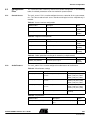
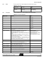
6.2.1
Control Access .................................................................................6-47
6.2.2
Audio Features .................................................................................6-47
6.2.3
Clock.................................................................................................6-49
6.2.4
File System.......................................................................................6-49
6.2.5
Setting ..............................................................................................6-50
6.2.6
Keyboard ..........................................................................................6-50
6.2.7
LCD Display......................................................................................6-53
6.2.8
MMC / SD Card ................................................................................6-54
6.2.9
MMI Applications ..............................................................................6-55
6.2.10 Nand-Flash Memory .........................................................................6-56
6.2.11 Power Management .........................................................................6-56
6.2.12 Scheduler module.............................................................................6-57
6.2.13 USB Module .....................................................................................6-58
6.2.14 Firmware update...............................................................................6-59
AT85C51SND3Bx Firmware User’s Guide
3
7691A–MP3–08/07
Section 1
Introduction
The AT85C51SND3Bx is a low power single-chip highly-integrated digital audio
decoder/encoder for applications such as audio players, recorders, cell phones, toys…
The AT85C51SND3Bx MP3 Player firmware is part of the AT85DVK-07 development kit
or the AT 85RF D-0 7 r efer ence des ign dedic ated to the AT 85C5 1SND3B x
microcontroller.
This document is the User’s Guide of the AT85C51SND3Bx MP3 Player firmware.
The topics covered are:
the functional features and options that the firmware brings
how the firmware source code files are organized
the firmware architecture
how to configure the firmware
the MMI layer
The AT85C51SND3Bx firmware described in this document has been developed to run
on the AT85DVK-07 as well as the AT85RFD-07.
For more information on the AT85DVK-07 development board, refer to the documents
“AT85DVK-07 Hardware User’s Guide” and “AT85DVK-07 Demonstration Firmware
User’s Manual”, available on the Atmel web site.
For more information on the AT85RFD-07 development board, refer to the documents
“AT85RFD-07 Hardware User’s Guide” and “AT85RFD-07 Demonstration Firmware
User’s Manual”, available on the Atmel web site.
AT85C51SND3Bx Firmware User’s Guide
1-1
7691A–MP3–08/07
Section 2
Firmware Features
The following sections describe the AT85C51SND3Bx firmware features and options.
Some of the firmware options are not supported by the AT85DVK-07 (e.g. image viewer)
or by AT85RFD-07 (e.g. MMC support).
2.1
MMI Manager
This module allows customers to easily develop their own MMI applications.
2.1.1
Features
Application management
– execute
– kill
Mailbox management
– send command to system drivers
– get event from system drivers or MMI applications
– forward event to MMI applications
2.1.2
Configuration
Software timers
Animated icons
Applications names
MMI events creation
2.2
Device USB
This module is the USB mass-storage driver.
2.2.1
Features
USB 2.0, High and Full Speed Transfer
Class provide : Mass Storage, HID, CDC.
Mass Storage Class :
– rate performance :
typical, 10MB/s read - 8MB/s write on NandFlash
up to 12MB/s on MMC V4 / SD / SD HC
– Supported hosts : Win XP, Win 2K, Mac OSx, Linux
– Secure disk option content through password management
AT85C51SND3Bx Firmware User’s Guide
2-3
7691A–MP3–08/07
Firmware Features
2.2.2
Configuration
Connection Speed
– authorize high or full speed (depending on the host)
– authorize only full speed
enable/disable USB Class used (Mass Storage, HID, CDC)
USB device information (vendor ID, product ID, manufacturer name, ...)
– product name
– serial number
Class description (Class name, ...)
enable/disable Disk Password Management (for Mass Storage Class)
2.3
Host USB
This module is the USB host driver.
2.3.1
Features
Reduced host implementation
USB 2.0 full speed transfer with USB device
USB class provide:
– HUB
– Mass-storage (e.g. Udisk, multi-card reader)
– HID
– CDC
2.3.2
Configuration
2.4
Audio Player
This module allows the end-user to play some audio stream.
2.4.1
Features
enable/disable USB class supported
Audio stream
– MP1, MP2, MP3
– WMA
– WAV (PCM, G711, G726)
Stream management
– play
– pause
– stop
– next track
– previous track
– fast Forward
– fast Rewind
– repeat A/B
– speed Adjust (MP1, MP2, MP3 only)
2-4
7691A–MP3–08/07
AT85C51SND3Bx Firmware User’s Guide
Firmware Features
Stream Information
– synchronized play time
– bit rate
– sampling frequency
– number of channels
Tags
– ID3 v1.0, v1.1
– ID3 v2.2 and v2.3
Stereo volume control
Sound effects:
– bass boost
– spatial sound
Adjustable 3-band EQ
– Classic, Pop, Jazz, Rock…
2.4.2
Configuration
DAC Output Selection
– internal
– external
External DAC interface
2.5
Audio Recorder
This module allows the end-user to play and record audio streams.
2.5.1
Features
Recording (codec G726)
Input line in and micro
line in gains (analog & digital)
micro gains (analog & digital)
2.5.2
Configuration
2.6
Image Viewer
This module allows the end-user to display images.
2.6.1
Features
Supported Image Format:
– BMP
– JPEG
Automatic Resize
2.6.2
Configuration
None
2.7
Settings
This module allows the user to manage user data in the setting segment located in the
customer or reserved data area of the Nand Flash.
AT85C51SND3Bx Firmware User’s Guide
2-5
7691A–MP3–08/07
Firmware Features
2.7.1
Features
Management
– load
– save
– update from a file
2.7.2
Configuration
Opened Settings structure content
Update file name
2.8
Update
This module allows the end-user to perform firmware update of its player.
2.8.1
Features
Firmware, codecs, display, fonts update
No PC tool install required for end-user
Power failure resistant
Update file generated by the Atmel In System Programming tool
Enable/disable update module
Enable/disable update auto-start at power-up
If update auto-start is enable then configuration of “File Location” on Nand Flash or
MMC/SD card.
enable/disable file erase after update (always enable in case of update auto-start)
2.8.2
Configuration
2.9
File System
This module allows management of the file system present in the Nand Flash memory
the MMC/SD card, the USB host disk, or through SIO, SPI….
2.9.1
Features
FAT12, FAT16, FAT32
ASCII and/or Unicode
More than one file/disk opened at a time
File management
– file information
– I/O access
– create
– copy
– paste
– delete
– rename
Directory management
– directory information
– enter
– go to root
– exit
2-6
7691A–MP3–08/07
AT85C51SND3Bx Firmware User’s Guide
Firmware Features
– create
– delete
– rename
Disk management
– disk Information
– format: FAT12, FAT16, FAT32
2.9.2
Configuration
Supported file systems
Maximum number of files to manage at same time
Cache optimization
2.10
Nand Flash
This module is the Nand Flash memory library.
2.10.1
Features
Support Nand Flash SLC small or large blocks (16KB or 128KB)
10MB read / 7MB write with 1 Nand Flash
Physical system area
– code with redundancy
– codecs with redundancy
– pictures
– fonts
Logical data area
– proprietary wear-levelling algorithm with ECC management
– settings segment: user reserved data
– secure disk segment: mass storage disk for Data disk security management
– data disk segment: mass storage disk
2.10.2
Configuration
Nand Flash auto-detection (average performance)
Nand Flash part number (best performance)
Number of devices: 1, 2, 4
2.11
MMC® SD® Cards This module is the memory card library.
2.11.1
Features
MMC cards:
– V3 in 1-bit mode at 20 MHz
– V4 in 4-bit mode at 24 MHz
SD cards:
– SD 4-bit mode at 24 MHz
– SD HC 4-bit mode at 24 MHz
AT85C51SND3Bx Firmware User’s Guide
2-7
7691A–MP3–08/07
Firmware Features
2.11.2
Configuration
Enable/disable
Bus format:
– automatic: depends on card type
– 1-bit
2.12
Display
This module is the display management library.
2.12.1
Features
2.12.2
Configuration
Interface configuration to fit display controller
– type: I80/6800
– timings
2.13
Keyboard
This module is the keypad driver.
2.13.1
Features
Matrix choice leads to dedicated hardware schematic
Automatic event generation:
– key press
– key release
– key repeat
– key long press
2.13.2
Configuration
Matrix size:
– from 4 keys up to 12 keys
Keypad timings:
– debounce
– auto-repeat start
– auto-repeat interval
– long press
2.14
Power Manager
This module is the system power driver.
2.14.1
Features
Dynamic power management
Battery level information
Power on/off
Power source:
2.14.2
Configuration
– DC-DC, Regulator…
– voltage
2-8
7691A–MP3–08/07
Power off
AT85C51SND3Bx Firmware User’s Guide
Firmware Features
2.15
Clock Manager
This module is the system clock driver
Oscillator Frequency
Clock Type:
– crystal
– oscillator
2.16
System
2.16.1
Features
2.16.2
Configuration
Memory mapping configurable (code & data)
Code swap between SND3 and Nand Flash (use system area code)
Store a large constant data in the NandFlash (use system area font and display)
Memory mapping
Banking code space
AT85C51SND3Bx Firmware User’s Guide
2-9
7691A–MP3–08/07
Section 3
Source Files Organization
3.1
Directory Physical Structure
The AT85C51SND3Bx MP3 player firmware source code is composed of several files.
This section describes the directory organization of the firmware package.
3.1.1
snd3b-dvk-x_y_z
Directory
The snd3b-dvk-x_y_z directory contains the firmware package where x_y_z is the firmware version.
.................ISP files: codec, picture_, font
.............................................user’s system configuration files
.............................................user’s MMI peripherals high-level API source code
.............................................Atmel MCU peripherals drivers source code
.............................................Atmel high-level memory storage drivers source code
.............................................Atmel system services source code
.............................................user’s MMI applications source code
.............................................Atmel system modules source code
.............................................code hex and object files
.............................................Atmel firmware tools
.............................................versions history
.............................................Atmel system core configuration
.............................................end user license agreement
.............................................target code download tool for debug mode
.............................................the C language main() function of the firmware
.............................................peripherals option. Used as compilation switches
.............................................Keil project option file
.............................................player.uv2: Keil project file
.............................................basic description and basic getting started
3.1.2
_isp_modules
Directory
The _isp_modules directory contains the files used for In System Programming.
................codec binary files
.............................................font binary files
.............................................pictures binary files
.............................................ISP tool project file
AT85C51SND3Bx Firmware User’s Guide
3-11
7691A–MP3–08/07
Source Files Organization
3.1.3
conf Directory
The conf directory contains header files allowing user to configure the Atmel libraries. Its
content is detailed in Section 6.
............conf_access.h: configuration of the memory access interfaces
.............................................conf_audio.h: configuration of the audio part (HW and SW)
.............................................conf_clock.h: configuration of the oscillator frequency
.............................................conf_explorer.h: configuration of the FAT and the navigator
.............................................conf_kbd.h: configuration of the keyboard (HW and SW)
.............................................conf_lbd.h: configuration of the LCD (HW and SW)
.............................................conf_lbd.h: configuration of the SD/MMC interface
.............................................conf_mmi.h: configuration of the MMI behavior
.............................................conf_nf.h: configuration of the nand-flash
.............................................conf_power.h: configuration of power (HW and SW)
.............................................conf_scheduler.h: scheduling of the tasks
.............................................conf_update.h: configuration of the firmware upgrade
.............................................conf_usb.h: configuration of the USB interface
3.1.4
drivers Directory
The drivers directory contains the user’s MMI peripherals high-level API source code.
.............................user’s external DAC drivers
.............................................user’s FM receiver drivers
.............................................user’s LCD display drivers
.............................................user’s high-level API source code to display MMI graphical objects
3.1.5
lib_mcu Directory
The lib_mcu directory contains the AT85C51SND3Bx core and peripherals drivers
source code.
.....................Audio Processor driver
.............................................Clock Manager driver
.............................................Data Flow Controller driver
.............................................Interrupt controller driver
.............................................Keyboard drivers
.............................................Display interface driver
.............................................MultiMediaCard drivers
.............................................Nand Flash Controller driver
.............................................Power management driver
.............................................Parallel Slave Interface driver
.............................................Serial I/O port driver
.............................................Memory space management driver
.............................................Timers driver
.............................................Universal Serial Bus controller driver
.............................................WatchDog Timer driver
.............................................Generic macro-functions define to get rid of compiler specificities
.............................................Routines of debug trace and assert
.............................................Routines of debug trace and assert
.............................................AT85C51SND3Bx SFR registers description file
.............................................AT85C51SND3Bx SFR registers description file
.............................................Include file to enable and put traces
Note:
3-12
7691A–MP3–08/07
mcu_drv.h file defines a list of masks related to peripherals controller and provides a list
of macro-functions that maps SFR and pages.
The AT85C51SND3Bx implements a SFR pagination mechanism which allows mapping
of high number of peripherals in the SFR space. Four pages are accessible through the
PPCON register.
AT85C51SND3Bx Firmware User’s Guide
Source Files Organization
3.1.6
lib_mem Directory
The lib_mem directory contains the Atmel high-level memory storage drivers source
code.
.....................MMC/SD memory card driver
.............................................Nand-Flash memory driver
3.1.7
lib_system Directory The lib_system directory contains the Atmel system service source code.
......................automatic display of time-depending graphical objects
.............................................code banking load & swap source code
.............................................inter-process communication library source code
.............................................memory manipulation routines
.............................................boot sequence source code
.............................................software timer library
.............................................unicode management library
.............................................miscellaneous C language manipulation routines
3.1.8
mmi Directory
The mmi directory contains the user’s MMI application source code.
Note:
This directory content may vary from reference-design firmware to development-kit
firmware.
.......................MMI module template
.............................................dummy application required for code banking mechanism
.............................................MMI equalizer control application
.............................................MMI file system explorer application
.............................................MMI games application
.............................................MMI default application
.............................................MMI display images (fonts & pictures)
.............................................MMI information & system status display application
.............................................MMI keyboard high-level driver
.............................................MMI lyrics display application
.............................................MMI mass-storage application
.............................................MMI audio player application
.............................................MMI playlist management application
.............................................MMI radio application
.............................................MMI recorder MMI control
.............................................MMI contextual menu application
.............................................MMI setting management module
.............................................MMI shared functions
.............................................MMI start-up application
.............................................MMI status control application
.............................................MMI firmware update application
.............................................MMI image viewer application
.............................................MMI volume control application
AT85C51SND3Bx Firmware User’s Guide
3-13
7691A–MP3–08/07
Source Files Organization
3.1.9
modules directory
The modules directory contains the Atmel system libraries source code.
...............audio controller library
.............................................memory access and data transfer libraries
.............................................FAT file system library
.............................................MMI manager library
.............................................audio player library
.............................................power management library
.............................................audio recorder library
.............................................firmware scheduler library
.............................................firmware update library
.............................................USB management library
.............................................Picture viewer library
3.1.10
Tools directory
The tool directory contains the Atmel image converter as well as the project images.
.............MMI pictures and image converter tool
.............................................Windows® USB drive secure executable
3.2
Directories
Logical
Organization
This purpose of this view is to show the logical links between the directories.
mmi directory
Customer MMI
firmware
modules directory
lib_system directory
drivers directory
lib_mem directory
Atmel System
firmware
lib_mcu directory
AT85C51SND3B chip
These source file directories can be grouped into two firmware parts:
– the customer MMI firmware
– the Atmel system firmware
The customer MMI firmware is the code source you have to develop and customize from
the software platform delivered with this package. Indeed, this layer is dedicated to interface the user with the high-level services provided by the Atmel core firmware and the
AT85C51SNDA chip. See Firmware Architecture Section 5.
The Atmel system firmware is the code source you should not modify since this layer
has been designed to provide full and high-performance services from a low cost chip.
Only the configuration files are to set in order to configure this layer to your application
requirements. See Firmware Configuration Section 6.
3-14
7691A–MP3–08/07
AT85C51SND3Bx Firmware User’s Guide
Section 4
Code & Data Management
4.1
Principle
The SND3 chip permits:
to customise the memory organisation
to use a code swap feature (= code banking)
to store a large constant data in the NandFlash
Reminder: The C51 core use different memory space (code, data, xdata). The size of
data space is 256B. The size of code space is limited at 64KB and xdata space is limited
at 64KB.
4.1.1
Custom memory
organisation
The AT85C51SND3B chip uses a 64KB of RAM to store the data and code, this particularity permits to configure the memory size according to your needs.
4.1.1.1
Rules
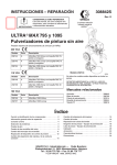
xdata space size + code space size = 64KB – 512B
code space size = code common size + code bank size*
AT85C51SND3Bx Firmware User’s Guide
4-15
7691A–MP3–08/07
Code & Data Management
xdata space size, code common size and code bank size* shall be a modulo 512B.
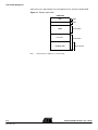
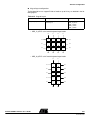
Figure 4-1. Memory organisation
64KB RAM
data
256B
reserved
256B
xdata
Customizable
bank code
Customizable
common code
Note:
4-16
7691A–MP3–08/07
Customizable
*code bank size is optional, see “Code swap”
AT85C51SND3Bx Firmware User’s Guide
Code & Data Management
4.1.1.2
How to configure
You must change the configuration in the « option.h » header file by defining following
constants:
•
XDATA_LENGTH
•
CODE_BANKING
•
BANK_START_ADDRESS
Note:
There are no « code size » #define, because this one is automatically computed using
XDATA_LENGTH.
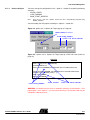
You must modify the UV2 project according to « option.h » header file;
Figure 4-2. options are in ‘Options for Target’ pop-up in Target tab
CODE_BANKING (ENABLED)
BANK_START_ADDRESS
= 64KB-512B- XDATA_LENGTH
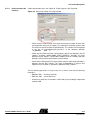
Figure 4-3. options are in ‘Options for Target’ pop-up in BL51 Misc tab (linker file
player.lin)
player.lin
BankArea(0xC200,0xE5FF)
PRINT(".\List\player.m51") RAMSIZE(256)
DISABLEWARNING (15)
BANK10(?CO?FILE(0xC200),?PR?ROUTINE?FILE,?PR?ROUTINE2?FILE)
…
BANK01(?CO?FILE2(0xC200),?PR?ROUTINE?FILE2,?PR?ROUTINE2?FILE2)
OVERLAY( main!(?CO?MMI_LYRICS,…))
CODE( 0x0000-0xE5FF )
XDATA( 0x0000-0x17FF )
BANK_START_ADDRESS
XDATA_LENGTH
64KB-512B- XDATA_LENGTH
WARNING : At compile time, there are no automatic coherency check between « UV2
project option » and « option.h » (no error and no warning). The execution code may be
corrupted if a difference exists.
AT85C51SND3Bx Firmware User’s Guide
4-17
7691A–MP3–08/07
Code & Data Management
4.1.2
Code swap
4.1.2.1
Principle
The code load swap consists in the downloading of temporary codes in a part of the
microcontroller code section to be executed immediately. When this temporary code has
been completely run, the microcontroller automatically runs back on the permanent
code or a previous temporary code. This makes it possible to have a code memory
space share for temporary codes, expanding then the total code beyond the 64KBytes.
Indeed, the downloading of code with deciphering produces a non-insignificant overhead time (above 0.1s). The critical code section, that is the system part, must react as
quick as possible with the hardware layer. Also, the code load swap must be rarely executed to not load the CPU with overhead routines to the detriment of the system
reactivity.
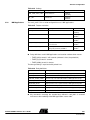
Figure 4-4. Code load swap representation
system code area
of Nand Flash
64KB RAM
data
bank N
reserved
bank N-1
xdata
...
bank code
Loading for each
bank change
bank 2
bank 1
common code
Loading once at startup
4.1.2.2
Mechanism
common code
The code load swap mechanism is based on the code banking frame available under
the environment Keil µ Vision. Indeed, the assembly file “lib_system\banking\l51_bank.a51” has been deeply customized by Atmel to link code-load-swap
routines to the code banking frame. Also, the debugger has been reworked to support
the code load swap and the downloading of code banks will be transparent for you in
debugging mode in a future software delivery.
Thus, the code-load-swap mode is fully supported under the environment Keil µVision
enabling you to develop software beyond the 64K of the code memory space without
difficulty.
4-18
7691A–MP3–08/07
AT85C51SND3Bx Firmware User’s Guide
Code & Data Management
4.1.2.3
How to activate code
banking?
Code banking enable are in the ‘Option for Targets’ pop-up in the Target tab.
Figure 4-5. Keil µVision ‘Option for Target’ window
– Check the box “Code Banking” and select the maximum number of banks that
your application may have to support. For information, the banking frame code
size increases with the number of available banks. This number must be reported
in the file “lib_system\banking\l51_bank.a51” at the following definition
“?B_NBANKS
EQU 4”.
– Check that the “Bank Area Start” value matches with the one defined in the file
“option.h” as follows: “#define BANK_START_ADDRESS 0xC800”. This value
defined in the file “option.h” should not be modified since this common code (not
banked) is mainly the one of the Atmel system firmware.
– Check that the “Bank Area End” value matches with the code range end address
defined in the tab “BL51 Locate”. This value, incremented by 1, must be also
reported in the file “option.h” at definition “#define XDATA_LENGTH …”.
The files building generates as many binary files as banks used with the following
extensions:
– B00, B01, B02, … for binary bank files
– H00, H01, H02, … for hex bank files
– All the binary bank files are created in a 64K code space including the duplicated
common code.
AT85C51SND3Bx Firmware User’s Guide
4-19
7691A–MP3–08/07
Code & Data Management
4.1.2.4
How store a file in a
bank ?
To store all routines from a C file in a bank , you must set a bank number in file options
in KEIL.
Figure 4-6. Banking a C file
Note:
The bank #0 is not to be used, it is reserved for the proper working of the code load swap
mechanism. Indeed, it’s the MMI application “mmi_dummy” that takes up this bank
although the application does nothing. This configuration must not be modified.
If the constant code present in C file banked are used only in C file, then you can bank
the constant code in the same bank. Add the line “?CO?FILE_NAME” in the corresponding bank field in player.lin file, e.g. :
BANK7(?CO?FAT_UNUSUAL(0xBE00),?CO?SETTING)
Note:
4.1.2.5
How store a routine
in bank ?
It is not autorized to bank constant code if the file is not banked.
To store a routines in a bank, add the line “?PR?ROUTINE?FILE_NAME” in a bank field
in player.lin file, e.g. :
BANK7(...(0xBE00),?PR?NAV_FILE_RENAME?NAVIGATION)
4.1.2.6
Banking
organisation in
ATMEL firmware
The Atmel firmware stores in the same bank all modules which are used for the same
mode.
e.g. :
in BANK 2, there are the file mmi_player.c, srv_player.c, player.c which are call only in
player mode. The player_task.c isn’t banked because is call always by scheduler in all
modes.
All MMI and service files are stored in bank space excepted the MMI files low level
which are dedicated to translate hardware or system events in actions or informations to
the other MMI applications that are in charge to supervise the functional modes (Ex.:
mmi_status, mmi_info, …).
If a routines or modules don’t correponding at a specific mode but there are few call or
never call, then ATMEL firmware store this one in a bank.
e.g.:
BANK7(?CO?FAT_UNUSUAL(0xBE00),?PR?NAV_FILE_RENAME?NAVIGATION)
4-20
7691A–MP3–08/07
AT85C51SND3Bx Firmware User’s Guide
Section 5
Architecture
5.1
Overview
The AT85C51SND3Bx firmware is a software platform that provides full and high-level
easy to use services. The architecture was carefully designed for both quick chip configuration and easy customizing.
This achievement is due to the splitting of the firmware in two parts:
The Atmel core firmware:
– provides full and high-level services (USB management, power management,
audio management, keyboard management, file explorer, …),
– provides API functions making deep abstraction of chip hardware
– manages the advanced running of the customer MMI applications
– must not be modified
– must be only configured with the help of configuration files
In a nutshell, the firmware core acts as a multimedia Operating System
The Customer MMI firmware:
– interfaces the external custom MMI devices (Keyboard, LCD)
– provides high-level features to the user (audio control, player control, file
exploring), thanks to the Atmel core firmware services
– gets the Atmel core firmware services with the help of requests and feedbacks
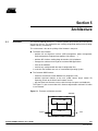
The Figure 5-1 gives an overview of this firmware organization and how it fits within
its environment.
Figure 5-1. Firmware architecture overview
Firmware
Customer MMI
info
keypad
AT85C51SND3Bx Firmware User’s Guide
request
ATMEL core
LCD
5-21
7691A–MP3–08/07
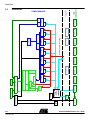
Architecture
CUSMTOMER
MMI
mmi_storage
TASK
device
USB
host
ATMEL MODULES
mmi_player
srv_recorder
mmi_recorder
recorder
TASK
mmi_viewer
viewer
TASK
Features direct access
srv_player
TASK
player
codecs
mmi_update
mmi_explorer
srv_explorer
TASK
explorer
mmi_startup
TASK
power
mmi_status
keypad
Specifics
events
KERNEL
Nand Flash
LCD
CODE
SWAP
System Area con-
DEBUG
TEXT
(mail box)
(timer)
(MMI manager)
(scheduler)
Settings
Features commands/events access
TASK
update
FILE SYSTEM
File I/O
Playlist
Explorer
Navigation
FAT 12/16/32
Disk control
MMC/SD
7691A–MP3–08/07
AT85C51SND3Bx Firmware User’s Guide
5-22
ATMEL
SERVICES
Architecture
5.2
Architecture
5.3
KERNEL
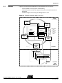
Figure 5-2 presents the execution process of the firmware, this one includes:
– a task scheduler to run many tasks simultaneously
– a communication based on message to manage the no foreeable commands
and events
– an MMI manager task to manage an MMI applications stack
Figure 5-2. Firmware architecture: worm’s eyes view
Atmel
core firmware
USB
task
Player
task
in
Round-robin
type
processing
of the
scheduled
tasks
Command
mailbox
Event
mailbox
out
in
out
Explorer
task
Power
task
Events
MMI
manager
task
Commands
MMI applications
MMI_APPLI_IDLE
MMI_APPLI_1
MMI_APPLI_2
SRV_APPLI
MMI_APPLI_N
Customer
MMI
firmware
AT85C51SND3Bx Firmware User’s Guide
5-23
7691A–MP3–08/07
Architecture
5.3.1
The Scheduler
The firmware system is driven by an endless scheduler which activates tasks, one at a
time, in a round robin manner. The scheduler loops on a static list. Refer to Section
6.2.12 for configuring the scheduler.
Note that each task executes “at will”, i.e. the duration of their execution is not limited.
Thus, in order to have the system running smoothly, each task should perform its duty
for the shortest amount of time.
5.3.2
The Tasks
Task is a generic entity that provides well-defined services to the Customer MMI layer. It
integrates the on-chip peripherals and the software layer that controls them and provides high-level information.
Figure 5-3. Inner task logic representation.
Round-robin scheduler
Task
Command/Event
Communication
interface
Public routines
Processing
management
Drivers
On-chip
peripherals
On-board devices
The Atmel demo firmware implements 8 tasks:
– MMI manager task
– Power task
– USB task
– Player task
– Recorder task
– Viewer task
– Explorer task
– Update task
5.3.3
The Inter-Task
Communication
The bi-directional communication system between tasks is based on the management
of two kind of messages: “command” and “event”.
5-24
7691A–MP3–08/07
“command” is a request that a task does a specific action. The “command”
messages can be mailed by tasks or MMI applications. They are destined to all
tasks except the MMI manager task.
AT85C51SND3Bx Firmware User’s Guide
Architecture
“event” is an information dedicated to MMI applications, sent by a task to inform on
its status or to give feedback of a previously executed command.
These messages are mailed in two separate mailboxes, based on FIFO stacks.
The uni-directional communication system is the direct access at the public routines provide by modules.
5.3.3.1
Message Format
Command and event messages are composed of 2 words:
– a unique ID
– an optional 16-bit parameter
Command message format
Figure 5-4. Command message format
cm d _id
task_id
15
param
task _cm d_id
8
7
0
15
8
7
0
The command message ID is composed of two bytes that define:
– the task to which this message is dedicated (“task_id”)
– the ID of one of the task commands to execute (“task_cmd_id”)
Command messages are defined in the file “lib_system\mailbox\mail_cmd.h”.
Event message format
Figure 5-5. Event message format
param
evt _id
7
0
15
8
7
0
The event message IDs are 8-bit values. One of the tasks are frozen and defined in the
file “lib_system\mailbox\mail_evt.h”.
Event messages can be defined by the customer to make possible specific communications between MMI applications. These must be defined in the custom file
“mmi\common\com_evt.h”.
Message parameter
The optional “param” is a 16-bit argument being able to pass data of different types:
– one or two single bytes with the help of the macros LSB(), MSB():
LSB(param) = byte1; MSB(param) = byte2;
– the address of data, on 16 bits only although supplementary bits are required to
get the complete address of data. Thus, the memory type to which the data
belongs must be known at the delivering of this kind of message to point properly
the data.
// Preparation in message mailing
xdata U8 table[10];
param = U16( &table[0] );
// Message delivery
_MEM_TYPE_SLOW_ U8* ptr_table;
ptr_table = (xdata U8*) param;
AT85C51SND3Bx Firmware User’s Guide
5-25
7691A–MP3–08/07
Architecture
5.3.3.2
Messages
Management
The following functions located in file “lib_system\mailbox\mail.c” make it possible the
mailing and the delivery of messages.
Figure 5-6. Mailbox interface functions
Command
mailbox
mail_send_command(
U16 cmd_id, U16 param );
mail_get_command(
U8 task_id, Msg *p_cmd_msg );
mail_send_command(
mail_get_command(
CMD_USB_START, 0 );
TASK_MASS, &cmd_msg );
Event
mailbox
mail_send_event(
mail_get_event(
U8 evt_id, U16 param );
U8 task_id, Msg *p_evt_msg );
mail_send_event(
EVT_USB_POWERED, 0 );
mail_get_event(
TASK_MASS, &evt_msg );
These two mailboxes can store up to 8 messages according to the configuration done in
file “config.h”.
5.3.4
MMI Manager task
The MMI Manager task (also named “mmgr_kernel”) is dedicated in the management of
the MMI applications. It can be split into three processes:
– Keyboard management: filters key bouncing and mails event messages when
actions on keys
– Software timers: are 32-bit timers dedicated to MMI applications and mails event
messages when the timer overflows
– Application manager: manages the execution of MMI applications running at the
same time and mails some events
5.3.4.1
Application Manager
Principles
5-26
7691A–MP3–08/07
The management of MMI applications is based on a LIFO stack that keeps in memory
the applications launched and runs them in the order in which they have been launched.
Thus, the last application launched (being at the top of the stack) is the first executed to
treat the input event. If this event was not dedicated to the top application, it is forwarded
to the following one stacked. Thus, several applications can be launched and run independently at the same time, making easy and flexible the development of the custom
MMI layer. See Figure 5-7.
AT85C51SND3Bx Firmware User’s Guide
Architecture
Figure 5-7. MMI manager principle
evt
last launched
application is
placed at the top
p
r
o
c
e
s
s
i
n
g
highest
priority
evt
evt
cmd
in
out
MMI_APPLI_X
MMI_APPL_IDLE
MMI_APPLI_X
MMI_APPLI_STATUS
...
MMI_APPLI_IDLE
MMI_APPLI_STATUS
lowest
priority
LIFO application
stack
customer
applications
mmi manager kernel
The MMI application “status” is loaded first in the application stack at the initialization of
the MMI manager task. So, it’s always the first MMI application executed since it temporarily manages the start-up and then is in charge of managing the status of hardware
devices commonly shared with the majority of MMI applications.
The MMI application “status” has also launched the application “idle”. Indeed, some
functions and macros make it possible to launch the MMI applications from other ones
and request their finalization.
AT85C51SND3Bx Firmware User’s Guide
5-27
7691A–MP3–08/07
Architecture
5.4
MMI Applications MMI applications are source code executed under the control of the MMI manager kerel.
To achieve this control and to offer flexibility, they organized in modules, are based on a
template and are associated to IDs. This one can be use a services MMI which include a
usual code sequence to use provided by ATMEL.
5.4.1
Application IDs
Two kinds of 8-bit ID are associated to MMI applications:
Module ID
ID making statically reference to a MMI application, defined by the customer. It’s with
the help of this ID that a MMI application can be executed.
Process ID
ID dynamically linked to a MMI application at the time of its pushing in the stack and kept
until it is terminated by an action. This ID enables an application to know if the launched
application is still activated or placed at the top of the stack. As the process ID is unique
contrary to the module ID, several applications of the same type can run at the same
time without problem of identity usurpation.
5.4.2
Generic Modules
All MMI applications must integrate the following rules to keep the actual and new code
readable (“custom” is to replace with the functionality name of new MMI application to
develop):
Source code files
– named as “mmi_custom.c/h
– located in a new folder “mmi\custom”
– template available at location “mmi\_template”
Application module ID
– label definition with a unique value: #define MMI_APPLI_CUSTOM value
– located in “mmi\shared\com_appli.h”
– used to launch the application custom
Interface function with the MMI manager kernel
– prototype
to
declare
in
the
common
MMI
application
“mmi\shared\com_appli.h”: void custom_mmi_appli(U8 event, U16 param);
file
– definition to do in “mmi_custom.c”
– reference to integrate in the switch-case of the function “call_mmi_appli()” in the
file “mmi\shared\com_appli.c”
5-28
7691A–MP3–08/07
Internal processing of the interface function
AT85C51SND3Bx Firmware User’s Guide
Architecture
– a “switch-case” processes all in-coming events
Figure 5-8. internal switch-case processing
This minimal structure to respect is to get a proper control of all new MMI applications by
the MMI manager kernel.
The three basic system events “EVT_START_APPLI”, EVT_APPLI_KILLED”,
EVT_BACK_TO_TOP” and others are defined in “lib_system\mailbox\mail_evt.h”.
5.4.3
Useful Functions
A set of functions and macros enabling the MMI applications to interface to the MMI
and Macro-functions manager kernel are listed in the two separate tables for requests and status.
Requests
The request table Table 5-1 gives precisely the running priority of the requests since
they are not executed in the order of their calls. Indeed, the MMI manager kernel translates all requests into events, treated with more or less delay according as they are
mailed or not.
A non-mailed event is executed immediately by the MMI manager kernel when it takes
control led by MMI applications.
A mailed event is a commonly treated after the scheduler has completed a cycle. It shall
be executed just after the all non-mailed events are treated in order to maintain the
event mailbox half empty before giving back control to the system firmware.
AT85C51SND3Bx Firmware User’s Guide
5-29
7691A–MP3–08/07
Architecture
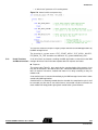
Table 5-1. Requests from MMI applications to MMI manager kernel
Functions or Macro-functions
mmgr_activate_mmi_appli(
U8 id_appli, U16 param )
Description
Name
Mailed
3(4)1
EVT_START_APPLI
yes
Launches an MMI application by pushing it in the application
stack with the help of two arguments:
- id_appli: the module id defined by the developper in file
“mmi\shared\com_appli.h”
- param: extra 16-bit parameter.
The application is normallyexecuted after a scheduler round.
Returns the associated unique id delivered by the application
stack.
Mmgr_krn_forward_current_event()
Forwards the current event since not caught by the current
application.
Mmgr_kill_this_mmi_appli_with_ret
_val( U8 val )
Terminates the current application by popping the MMI
application out of the application stack.
This immediately gives control to the following stacked
application with the help of a specific non-mailed event
“EVT_APPLI_KILLED”.
Idem as “Mmgr_kill_this_mmi_appli()” but additional information
is stored in the 16-bit parameter of the event
“EVT_APPLI_KILLED”:
killed application process ID in the MSB
Current event:
2
This immediately gives control to the following stacked
application with the help of this event.
Mmgr_kill_this_mmi_appli()
Event
Run
Prior.
EVT_ …
EVT_APPLI_KILLED
1
4(3)
1
EVT_BACK_TO_TOP
no
no
yes
8-bit data in the LSB
Mmgr_krn_this_mmi_appli_is_full_s
creen()
Informs the MMI manager kernel that this current application has
a graphical full screen (Partial screen by default).
This information enables the MMI manager kernel to manage the
automatic screen refreshing.
This macro is to execute once in the “EVT_START_APPLI” code
section.
Mmgr_set_id_appli_not_defined()
Sets a custom variable containing the process id of a running
application to the value “MMI_APPLI_NOT_DEFINED” when this
application does not run anymore (not stacked).
Notes:
-2
No event
-
-2
No event
-
1. Run priority between these two requests depends on the call order
2. No impact on MMI application execution order
Status
Table 5-2. Status on MMI applications being executed by the MMI manager kernel
5.4.4
Automatic Screen
Refreshing
Functions or Macro-Functions
Description
Mmgr_is_this_appli_at_the_top()
Macro called by a MMI application to test if is at the top in the
application stack. Mainly used for drawing.
mmgr_is_appli_at_the_top(U8
id_process )
Function with a parameter “id_process”, value only returned by
“mmgr_activate_mmi_appli()”. Called by MMI applications to know if
such an application is at the top or not. Mainly used for drawing.
The automatic screen refreshing consists in the redrawing of application screens when
a top application has just been terminated. This mechanism is linked to the event
EVT_BACK_TO_TOP.
The automatic screen refreshing is done in two steps:
– First, the first application that has the feature “full screen” is searched from the
top of the stack.
5-30
7691A–MP3–08/07
AT85C51SND3Bx Firmware User’s Guide
Architecture
– Secondly, from this application up to the top one, their screens are redrawn one
after the others.
Thus, this mechanism makes it possible to redraw superimposed non-full-screen windows automatically.
5.4.5
Automatic display
The automatic display module is charged with managing the display of time-related
graphical objects. It enables to make easily animations from pictures placed in a special
directory “tools\picture_maker\pictures_demo_default\Animations”. The basic pictures
composing a future animation picture must be named as follows:
animationpicturename__index.bmp
index can be digits and letters: it is useful to define the integration order.
The animation pictures are generated at the same time as the other ordinary pictures by
the picture maker tool. Make live animation pictures in the firmware with the following
functions and macros:
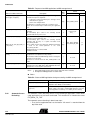
Table 5-3. Functions and macros controlling the automatic display
Functions or macros
Description
ad_allocate (U8 obj_type,
Ad_p_prm
_MEM_TYPE_SLOW_
*p_param_struct)
Allocates one of the graphical object slots still available and returns a 8-bit
ID. The ID is equal to “UNDEF_AD_OBJ” if failure in allocation.
If success, this ID is to store by the MMI application in order to control the
object with the help of the other functions and macros below.
Note:
No risk of object identity usurpation after a cold reset since the
value of “UNDEF_AD_OBJ” is 0.
Parameters:
Only object type is currently supported: AD_ID_ANIMATION.
The parameter structure “Ad_p_prm _MEM_TYPE_SLOW_” configured
the object in its appearance and its behavior. As the only one object type
actually supported is animation, the structure “Ad_p_prm” is always
“Ad_prm_animation” as follows:
typedef struct
{
U8 x;
//
U8 y;
//
U32 IDP;
//
U8 time_10ms; //
U8 mode;
//
}Ad_prm_animation;
ad_start( U8 id )
Starts the graphical object running
ad_pause( U8 id )
Suspends the graphical object in running
ad_stop( U8 id )
Stops the graphical object running and resets its state machine
ad_refresh( U8 id )
Requests the display refresh of the graphical object
Ad_free( U8 id )
Releases one of the graphical object and sets the variable storing the id to
the value “UNDEF_AD_OBJ” in order to prevent from identity usurpation.
Note:
5.4.6
Software Timers
x-coordinate
y-coordinate
ID of the animation picture
Time with 10ms granularity
Repeat: AD_SINGLE or AD_FOREVER
Event EVT_ANIMATION with parameter ANIMATION_END is mailed when animation
stops in mode AD_SINGLE.
The software timers are data structures integrating a 32-bit register. Their static values
are compared to the value of the tick counter every scheduler round. If the tick counter
value has reached a software timer time register, an overflow timer message is mailed
once.
AT85C51SND3Bx Firmware User’s Guide
5-31
7691A–MP3–08/07
Architecture
The number of available software timers is set to 10 using the macro
“NB_TIMER_SOFT”. The tick period is set to 2ms using the macro TICK_PERIOD.
These macros are defined in “config.h” and should not be modified.
The software timers are dedicated to MMI applications and dynamically attributed by the
software timer management. Some functions and macros enables the MMI applications
to control these kind of timers.
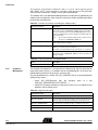
Table 5-4. Functions and macros controlling the software timers
Functions or macros
Description
ts_alloc()
Allocates one of the software timers still available and returns a 8-bit
ID. The ID is equal to “UNDEFINED_TIMER” if failure in allocation.
If success, this ID must be stored by the MMI application in order to
control its attributed timer(s) and to identify from which timers the
event comes from.
Note:
No risk of timer identity usurpation after a cold reset since
the value of “UNDEFINED_TIMER” is 0.
ts_set_time(U8 id, U32 delay)
Sets the 32-bit delay value, multiple of 2ms (tick period), with the id
of the software timer to configure.
ts_stop(U8 id)
Stops the time comparison and the software timer. This prevents the
delivery of overflow events from this timer.
Can only be reactivated with the help of the function “ts_set_time()”.
Ts_free(id)
Releases one of the software timers and sets the variable storing
the id to the value “UNDEFINED_TIMER” in order to prevent from
identity usurpation.
Table 5-5. Event returned from the software timers
5.4.7
Keyboard
Management
Event
Description
EVT_TIMER
Returns the 8-bit ID of the software timer that has just overflowed
The keyboard management is charged with the debouncing and the generation of
events from actions on keys. It is located in the file “mmi\kbd\keypad.c” and can be configured differently with the help of the file “conf\conf_kbd”.
Only one keyboard event is mailed “EVT_KEY_PRESSED” but its associated parameter
qualify the key actions:
– macro KEY_STATUS(param) gets the changing
(KBD_KEY_PRESSED, KBD_KEY_REPEAT, …).
status
of
a
key
– macro KEY_ID(param) identifies the key whose status has just changed (For key
definition, refer to Section 6.2.6).
Table 5-6. Keyboard messages
5-32
7691A–MP3–08/07
8-bit parameter value
Description
KBD_KEY_PRESSED
Key has just been pressed
KBD_KEY_REPEAT
Key has been pressed long enough to enter in the repeat mode.
This message is periodically sent while this key stands pressed.
KBD_KEY_LONGPRESSED
Key has been pressed long enough to send this message once.
KBD_KEY_RELEASED
Key has just been released after a key pressed.
KBD_KEY_REPEAT_RELEASED
Key has just been released from a repeat mode.
AT85C51SND3Bx Firmware User’s Guide
Architecture
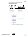
Figure 5-9 gives a graphical representation of the keypad behavior.
Figure 5-9. Keyboard timings and events
Key
Events
➊
➀
➋
➀
➁
Timings Tags:
➀ KBD_DEBOUNCE_TIMING
➁ KBD_REPEAT_START_TIME
➂ KBD_REPEAT_CONT_TIME
➃ KBD_REPEAT_LONG_TIME
➍
➌ ➌ ➌ ➌ ➌ ➌ ➌ ➌
➊
➀
➁
➎
➂ ➂ ➂ ➂ ➂ ➂ ➂
➃
➀
Events Tags:
➊ KBD_KEY_PRESSED
➋ KBD_KEY_RELEASED
➌ KBD_KEY_REPEAT
➍ KBD_KEY_LONGPRESSED
➎ KBD_KEY_REPEAT_RELEASED
Figure 5-10. Example of a key processing in MMI applications
AT85C51SND3Bx Firmware User’s Guide
5-33
7691A–MP3–08/07
Architecture
5.5
Services
The services are provide by Atmel and include the usual MMI sequences. This one permits to reduce the code in MMI Applications.
5.5.1
Player service
The player service provides a MACRO to start MMI_PLAYER with different options.
Table 5-7. Macro to start MMI_PLAYER
Fonctions
Description
Start_mmiplayer_resume()
Restore last variables of player service, to play the last played item
Start_mmiplayer_from_saving_options()
Restore all values of player service
Change the explorer values to play the current music file selected
Start_mmiplayer_on_disks()
Restore all values of player service
Change the explorer values to play all disks and start at the current position
Start_mmiplayer_on_disk()
Restore all values of player service
Change the explorer values to play one disk and start at the current position
Start_mmiplayer_on_dirsub()
Restore all values of player service
Change the explorer values to play the current dir with sub directory
Start_mmiplayer_on_dir()
Restore all values of player service
Change the explorer values to play the current dir without sub directory
Start_mmiplayer_one_file()
Restore all values of player service
Change the explorer values to play the current file only
Start_mmiplayer_on_playlist()
Restore all values of player service
Change the explorer values to play the current play list
Start_mmiplayer_on_playlist_at()
Restore all values of player service
Change the explorer values to play the current play list at a specific position
Table 5-8. Player services
Fonctions
srvplayer_restore()
Description
Copy player field from setting datas to the service variables
Note: it must be called before the other routines of player service.
srvplayer_save()
srvplayer_explorer_init()
Copy player field from service variables to the setting datas
Initialize the explorer module which permits to play many files in many modes (repeat, random).
Note: Don’t use this one, if you play a file include it in a specific list.
srvplayer_explorer_close()
Close explorer module
srvplayer_switch_on()
Turn ON the player modue
srvplayer_switch_off()
Turn OFF the player modue
srvplayer_file_getinfos()
Get static information about file (name, ID3)
srvplayer_play()
Start play of current file selected at beginning or at specific time position
srvplayer_update_bitrate()
Update bitrate information
Note: The codec type, channel type, sampling frequency, and bitrate informations are avialable only when
file is played.
srvplayer_gettime()
Get current time play
srvplayer_stop()
Stop play file
srvplayer_volume_send()
Send at player module the volume value
Note: Change “srvplayer_g_arg.volume” value before
srvplayer_volume_change()
5-34
7691A–MP3–08/07
Increment or decrement “srvplayer_g_arg.volume” value and send its.
AT85C51SND3Bx Firmware User’s Guide
Architecture
Fonctions
Description
srvplayer_set_eq()
Send to player module the equalizer value
srvplayer_eq_modify_predef()
Copy the predefine ambiance in the user ambiance definition
srvplayer_set_bassboost()
Send toplayer module the bassboost state
srvplayer_set_vsurround()
Send toplayer module the virtual surround state
srvplayer_set_speed()
Send toplayer module the speed level
srvplayer_pause()
Pause the play of current file
srvplayer_ffw()
Start fast foward
srvplayer_frw()
Start fast rewind
srvplayer_restart_play()
Restart play after a pause/ffw/frw
srvplayer_set_marker_A()
Set a marker A on current play
srvplayer_set_marker_B()
Set a marker B on current play and start repeat AB
srvplayer_stop_repeatAB()
Stop repeat AB
srvplayer_rqt_bargraph()
Send a request to get a bargraph data
5.5.2
Recorder Service
Table 5-9. Recorder services
Fonctions
Description
srvrec_init()
Initialize the source of record (micro or line-in)
srvrec_start()
Create a file to record the sound (NandFlash\record\recordxxx.wav”)
Note: The fonction search a free name between record000.wav to record100.wav
Start record after file create
srvrec_stop()
5.5.3
Explorer service
Stop the recording
The explorer service provide a fonctions to manage a disk list or file list from a directory
with a extension filter. In this list, the fonctions manage a display list.
Table 5-10. Explorer services
Fonctions
Description
srvexp_init()
This one initializes the list, It is the first function to call. Paramater is the filter extension of list, the size of
DISPLAY list, and eventualy init the position of list at the current position of current navigator
srvexp_list_init()
Reinitialize the position of list at the current position of current navigator
srvexp_list_check()
This fonction check if the disk of current list is always available.
If list no available then the fonction reinit the list with disk list.
srvexp_list_build()
Force the list rebuild, so use this one after list modification (e.g. file delete)
srvexp_list_beguinning()
Go to the begining of list. the DISPLAY list corresponding at the beginning of file list
srvexp_list_end()
Go to the end of list. the DISPLAY list include the end of file list
srvexp_list_up()
Move up the DISPLAY list in file list
srvexp_list_down()
Move down the DISPLAY list in file list
srvexp_list_getname()
Get a file name of file selected in DISPLAY list
AT85C51SND3Bx Firmware User’s Guide
5-35
7691A–MP3–08/07
Architecture
Fonctions
Description
srvexp_list_getname_parent()
Get the name of directory or disk correponding at file list
srvexp_enter()
Enter in a disk/directory selected in DISPLAY list
Note: A new list is create and DISPLAY list corresponding at the beginning of list
srvexp_gotoparent()
Go to parent directory/disk
Note: A new list is create and DISPLAY list include the previous parent dir
srvexp_format()
Format the disk selected in DISPLAY list
srvexp_delete()
Delete a directory/file selected in DISPLAY list
srvexp_playlist_default_exist()
Ask if a default playlist exist
srvexp_playlist_select_in_list()
The file selected in DISPLAY list is the new default playlist
srvexp_playlist_select()
Select or create a new default playlist (“NandFlash\playlist\palylistxxx.mu3”)
srvexp_playlist_add()
Add the directory/file selected in DISPLAY list
srvexp_copy()
Select a file in DISPLAY list as source file for the futur paste action
srvexp_paste()
Paste the file, selected by previous copy action, in directory corresponding at current list
srvexp_paste_abort()
Abort paste
srvexp_select_pos()
Update current file system navigator at the position selected in DISPLAY list
5.5.4
Ebook service
The ebook service support the text file multilanguage (ASCII, UTF16LE, UTF16BE,
UTF8)
Table 5-11. Ebook services
5-36
7691A–MP3–08/07
Fonctions
Description
srvebk_open()
Open the current file selected in current file system navigator
srvebk_read()
Read the next line
srvebk_close()
Stop the recording
AT85C51SND3Bx Firmware User’s Guide
Architecture
5.6
Modules
Atmel provides the system modules which permit to use the SND3 chip feature.
The modules are USB, player, recorder, viewer, power, explorer and update.
The USB modules offers its services to the MMI applications with the help of commands/events or public routines. The following parts decribes the interfaces of each
module.
5.6.1
USB Interface
The USB module controls the USB device/host mode.
Table 5-12. USB commands
Command Label
Description
CMD_USB_START
Enable the USB controller
CMD_USB_STOP
Disable the USB controller
CMD_DEVICE_START
Start the device mode
CMD_DEVICE_STOP
Stop the device mode
CMD_HOST_START
Start the Host mode
CMD_HOST_STOP
Stop the Host mode
CMD_USB_FORCE_HIGH_SPEED
Force high speed in USB device mode
Table 5-13. USB events
Event Label
Description
EVT_USB_CTRL_POWERED
Voltage level on VBUS present
EVT_USB_CTRL_UNPOWERED
Voltage level on VBUS not present
EVT_USB_DEVICE_START
USB controller is entered in USB device mode
EVT_USB_DEVICE_STOP
USB controller is exit of USB device mode
EVT_USB_DEVICE_ENUM_HIGH
USB device mode enumerated in hight speed detected
EVT_USB_DEVICE_ENUM_FULL
USB device mode enumerated in full speed detected
EVT_USB_DEVICE_SUSPEND
Suspended state has been detected on USB bus
EVT_USB_DEVICE_WAKE_UP
Wake-up state has been detected on USB bus
EVT_USB_DEVICE_RESUME
Resume state has been detected on USB bus
EVT_USB_DEVICE_RESET
Reset state has been detected on USB bus
EVT_USB_DEVICE_SEND
USB device Class has sent data
EVT_USB_DEVICE_RECEIV
USB device Class has received data
EVT_USB_DEVICE_MS_STARTED
USB device Class mass storage has started
EVT_USB_HOST_START
USB controller is entered in USB host mode
EVT_USB_HOST_EXIT
USB controller is exit of USB host mode
EVT_USB_HOST_LIMITATION_HW
USB host module can’t install new device because a
hardware limitation is detected (product limitation).
EVT_USB_HOST_LIMITATION_SW
USB host module can’t install new device because a
software limitation is detected (change low configuration in
conf_usb.h).
EVT_USB_HOST_MS_CHANGE
A Mass Storage device has been detected or disconnected.
EVT_USB_HOST_HUB_CHANGE
A HUB device has been detected or disconnected.
EVT_USB_HOST_HID_CHANGE
A HID device has been detected or disconnected.
EVT_USB_HOST_HID_MOUSE_BTN1
USB host has receiv a event “clic bouton 1” via a HID device.
AT85C51SND3Bx Firmware User’s Guide
5-37
7691A–MP3–08/07
Architecture
Event Label
Description
EVT_USB_HOST_HID_MOUSE_BTN2
USB host has received an event “clic bouton 2” via a HID
device.
EVT_USB_HOST_HID_MOUSE_BTN3
USB host has received an event “clic bouton 3” via a HID
device.
EVT_USB_HOST_HID_MOUSE_MOVE
USB host has received an event “mouse move” via a HID
device.
EVT_USB_HOST_HID_KB_KEY
USB has received an event “key press” via a HID device.
EVT_USB_HOST_CDC_CHANGE
A CDC device has been detected or disconnected.
The USB module does not include public routines.
5.6.2
Player Interface
The Player module controls the audio features of the chip:
– it interfaces the audio processor
– it manages the playing of audio files (play, stop, pause, …)
In player module, only the bargraph feature can’t be immediatly executed, then this must
be executed via a command and event.
Table 5-14. Player commands
Command Label
CMD_PLAYER_GET_BARGRAPH
Description
Ask a bargraph data.
The result is sent by player task via a event.
The player task sends only one event “EVT_PLAYER” with differents arguments.
Table 5-15. Player event arguments
Arguments of “EVT_PLAYER”
PLAYER_BOF
Description
Beginning of the played file reached.
Note: player_task_stop() is automaticly executed.
PLAYER_EOF
End of the played file reached, the player is stopped.
Note: player_task_stop() is automaticly executed.
5-38
7691A–MP3–08/07
PLAYER_ERROR_UNDERRUN
Under-run occurred but play continues
PLAYER_ERROR_SYNCH
Audio processor synchronization lost but play continues
PLAYER_START_AB
Play of the AB track has restarted
PLAYER_EOF_AB
End of the played AB track, start the research of A position
PLAYER_BARGRAPH
Bargraph resultat of command CMD_PLAYER_GET_BARGRAPH
AT85C51SND3Bx Firmware User’s Guide
Architecture
Table 5-16. Player publics routines
Routines
Description
player_on()
Turn the audio controller on
player_off()
Turn the audio controller off
player_play_file()*
Play the music file selected on current file system navigator
player_restart_play()*
Restart playing at beginning
player_pause()*
Pause the ongoing play
player_stop()*
Stop a playing file and close file
player_fast_foward()*
Fast-forward the ongoing play
player_fast_rwd()*
Fast-rewind the ongoing play
player_set_marker_A()
Set the marker A at the current position in the ongoing play
player_set_marker_B()
Set the marker B at the current position in the ongoing play and start
AB repeat
player_stop_repeat_AB()*
Stop playing the AB track
player_set_speed()
Change the speed of the play (normal/slow)
player_linein_on()
Enable ouput audio from line-in
player_linein_off()
Disable ouput audio from line-in
player_set_volume()
Change the output volume level
audio_surround()
Set the virtual surround on/off
audio_bassboost()
Set the bass boost on/off
audio_set_vol_equalizer()
Set the bass/medium/treble band volume
player_get_time()
Get the elapsed time of the ongoing play
player_get_timetotal()
Get the total time of a song to play
player_channel_type()
Get information channel type on the current stream.
player_sampling_freq()
Get information sampling frequence on the current stream.
player_bitrate()
Get information bitrate on the current stream.
player_get_codec_type()
Get the codec type currently used.
player_task_start()
Enable player task (it must be call after player_play_file() successfull)
player_task_stop()
Disable player task (it must be call after player_stop() successfull)
Note:
5.6.3
Recorder Interface
* If the resultof this routine is successful, then you must wait a confirmation via specific
routine player_evt().
The Recorder module takes in charge the control of the audio recorder features of the
chip:
– it interfaces the audio processor
– it manages the recording of audio files (start, stop)
The recorder module does not include a command, but one event “EVT_RECORDER” with
different arguments.
Table 5-17. Recorder event arguments
Arguments of “EVT_RECORDER”
RECORD_EOF
Description
End of recording because of destination memory access fail.
Note: recorder_task_stop() is automaticly executed.
AT85C51SND3Bx Firmware User’s Guide
5-39
7691A–MP3–08/07
Architecture
Table 5-18. Recorder public routines
Routines
record_on()
Description
Initialize the record with:
- microphone or line-in as input.
- current file selected on current file system navigator.
5.6.4
Viewer Interface
record_off()
Stop the recording and close file
record_start()
Start the recording
record_gettime()
Get the recording time
recorder_task_start()
Enable recorder task (it must be call after record_start() successfull)
recorder_task_stop()
Disable recorder task (it must be call after record_off() successfull)
The Viewer module takes controls the picture decoder features of the chip:
– it interfaces the decoder processor
– it manages the decoding of picture files (start, stop)
The viewer module does not include a command.
Table 5-19. Viewer events
Events
Description
EVT_VIEWER_EOF
End of picture decoding.
Note: viewer_task_stop() is automaticly executed.
EVT_VIEWER_FAIL
Error during picture decoding.
Note: viewer_task_stop() is automaticly executed.
EVT_VIEWER_ERR_ACCESS_FILE
Error during access file
Note: viewer_task_stop() is automaticly executed.
Table 5-20. Viewer public routines
Routines
viewer_set_width()
Description
Set the width of the viewer display area.
Note: initialization mandatory before call viewer_on()
viewer_set_height()
Set the height of the viewer display area.
Note: initialization mandatory before call viewer_on()
viewer_set_x0()
Set the x0 of the viewer display area.
Note: initialization mandatory before call viewer_on()
viewer_set_y0()
Set the y0 of the viewer display area.
Note: initialization mandatory before call viewer_on()
viewer_config()
Config the viewer.
Note: initialization mandatory before call viewer_on()
5-40
7691A–MP3–08/07
viewer_on()
Start the picture file decoding. Use the current file selected on current
file system navigator.
viewer_off()
Stop the recording and close file
viewer_task_start()
Enable viewer task (it must be call after viewer_on() successfull)
viewer_task_stop()
Disable viewer task (it must be call after viewer_off() successfull)
AT85C51SND3Bx Firmware User’s Guide
Architecture
5.6.5
Power Interface
The Power module controls the power management of the device:
– automatically jumps in idle mode to reduce power consumption,
– provides battery level information,
– provides power-off control,
– provides alarm mechanism on a specified low battery level.
Table 5-21. Power commands
Command Label
Description
CMD_POWER_OFF
Turn the power off (CPU and peripherals stopped). Exit from this
hardware state by any key pressed.
CMD_AUTO_POWER_OFF_ENABLE
Enable to turn power off automatically when no key pressed during a
well-defined time (see Section 6.2.11)
CMD_AUTO_POWER_OFF_DISABLE
Disable the auto power off
CMD_BATTERY_CHARGE_ENABLE
Enable battery charging
CMD_BATTERY_CHARGE_DISABLE
Disable battery charging
CMD_GET_VBUS_STATE
Test if there is power on the USB
CMD_POWER_SETTING_LOADED
Returned Events
EVT_POWER_VBUS_STATE
with boolean state
Initialize the power off timeout with the value present in setting data.
Note: Execute this command after setting init or load.
Table 5-22. Power events
Event Label
Description
EVT_POWER_ON
The chip must restart after a power-down mode executed by command CMD_POWER_OFF.
EVT_BATTERY_CHARGING
Signal battery charging activation or disactivation (status in parameter)
EVT_BATTERY_LEVEL
Return the battery charge level with the help of the parameter formatted as follows: LSB(U16) = 8-bit
battery charge level
Periodically sent according to the configuration (see Section 6.2.11)
EVT_BATTERY_LEVEL_ALERT
Signals that the battery charge level is low
EVT_POWER_VBUS_STATE
Give the VBUS state after a VBUS change or command CMD_GET_VBUS_STATE
EVT_BACKLIGHT_OFF
Signal that backlight is disabled.
Note: This event is sent by lcd module.
EVT_POWER_ENTER_IN_POWEROFF
5.6.6
Explorer Interface
Inform that chip have no activity and may be set in power off.
The Explorer module is basically the entry point to the file system and proposes the following services:
•
Drive/Partition navigation and control (mount, format, get space...)
•
directory navigation and control (cd, setcwd, deldir, mkdir, getcwd…)
•
file list (= files in directory) navigation (next, previous, search...)
•
file list control (get size, create, rename, delete, …)
•
file list I/O (getc, putc, read_buf, ...)
•
copy/paste file
•
playlist management (open, create, mdoification, ...)
•
explorer API to permit a simple filter navigation :
– in disk, directory only, directory and subdirectory, playlist
– the feature is previous, next, repeat, random
AT85C51SND3Bx Firmware User’s Guide
5-41
7691A–MP3–08/07
Architecture
In this document, only the commands and events are described, because a specific document on FileSystem Atmel exists.
These services are available through public routines, only the copy/paste features may
be use via a commands/event to not break the scheduler.
The following commands and events replace the direct access at the routine
“nav_file_paste_state()”.
Table 5-23. Paste commands
Command Label
Description
CMD_EXP_PASTE_ENABLE
Enable the task paste, it must be call after nav_file_paste_start().
CMD_EXP_PASTE_DISABLE
Abort the task paste.
Table 5-24. Paste events
Event Label
Description
EVT_EXP_PASTE_FINISH
The paste is finish.
EVT_EXP_PASTE_FAIL
The paste is finish because a error has occurs.
Table 5-25. Specific events
5.6.7
Update Interface
Event Label
Description
EVT_EXP_MEMORY_MMCSD_CHANGE
A MMC or SD card is plug or unplug.
The Update module controls the firmware update.
Table 5-26. Update commands
Command Label
Description
CMD_UPDATE_START
Start the update process
Table 5-27. Update events
5-42
7691A–MP3–08/07
Event Label
Description
EVT_UPDATE_START
The update process start status
EVT_UPDATE_PROGRESSING
The update process is in progress
EVT_UPDATE_FINISHED_FAIL
The update process failed
EVT_UPDATE_ERR_COMMAND
An unknown command has been received
AT85C51SND3Bx Firmware User’s Guide
Architecture
5.7
Debug trace text
The TEXT TRACE feature is available only in OCD mode because the text trace is sent
to KEIL IDE via OCD dongle.
To use it, you must:
•
uncomment line 14 "#define _TRACE_ (ENABLE)" in debug.c
•
include following lines in C file to debug
#include "config.h"
#define _TRACE_ (ENABLE)
#include "lib_mcu\debug.h"
•
use debug routines provide in debug.c, e.g. :
trace("u8_toto=");
trace_hex( u8_toto );
trace("\n");
•
in case of code commun too large, you can comment the debug routines not use in
debug.c , e.g. :
/*
void trace_u32( )
{...}
*/
When you execute the firmware in OCD mode on KEIL, the trace are displayed in the
tab "Command" from "Output Window".
AT85C51SND3Bx Firmware User’s Guide
5-43
7691A–MP3–08/07
Section 6
Firmware Configuration
6.1
Overview
Several files have been implemented to help the software developer to quickly configure
the firmware.
The configuration files “conf_*.h” are all under the conf directory of the firmware package (see Section 3.1.1). There are four kinds of configuration files:
Files configuring the Customer MMI layer only
The file conf_mmi.h configures exclusively the Customer MMI layer and more precisely the MMI applications organized in modules (see Section 3.1.8).
Files configuring both the Customer MMI and the Atmel system layers
These files are the ones that configure the source code of custom MMI peripherals:
– conf_kbd.h: configures both the keyboard driver of the system firmware system
and the key affectation dedicated to the MMI modules using the keyboard.
– conf_lcd.h: configures the lcd driver of the system firmware system, the API of the
LCD driver and the mmi_manager module.
– conf_audio.h: configures both the custom audio firmware module for external
DAC implementation and the audio part of the player module.
– conf_update.h: configures both the application MMI update and the update
firmware module.
Files configuring the Atmel system layer only
– conf_access.h: enables the implementation of memory access interfaces only
required in your custom application. It mainly configures the source code files of
the control access firmware module.
– conf_clock.h: configures the oscillator frequency which depends all the lib_mcu
drivers: clock, lcd, timer, memory controllers, …
– conf_explorer.h: configures the file_system module and the playlist module.
– conf_nf.h: configures the nand_flash memory module and the Nand Flash
controller driver.
– conf_power.h: configures the power module, the audio module and the API of the
lcd driver.
– conf_scheduler.h: configures the scheduling of the system task.
– conf_usb.h: configures the USB controller driver (see Section 3.1.5), the USB
module and the SCSI decoder module.
AT85C51SND3Bx Firmware User’s Guide
6-45
7691A–MP3–08/07
Firmware Configuration
Files configuring the global firmware
Two files are under the top-level directory of the firmware package:
– config.h: configures the system. Should not be modified.
– option.h: configures (de-)activation of peripherals. Also, defines compilation
switches.
6-46
7691A–MP3–08/07
AT85C51SND3Bx Firmware User’s Guide
Firmware Configuration
6.2
Configuration
Files
This section describes feature by feature the available configuration. In the following
tables, the default parameters values are marked in square brackets.
6.2.1
Control Access
The “conf_access.h” file is used to configure the access control of all the system memories. The source code of each access interface and logical unit are compiled only if
enabled.
Table 6-1. Access interface configuration
Definition Label
Description
Values
ACCESS_CODEC
Codec input under control access
[ENABLE]
DISABLE
ACCESS_DISPLAY
Display input under control access
[ENABLE]
DISABLE
Table 6-2. Logical unit configuration
Definition Label
Description
Values
MEM_NF
Nand Flash memory access
[ENABLE]
DISABLE
MEM_MMC
MMC memory access
ENABLE
[DISABLE]
MEM_USB
USB memory access (available in USB host mode
only)
ENABLE
[DISABLE]
Table 6-3. Global protection in writing of all memories (no implemented)
6.2.2
Audio Features
Definition Label
Description
Values
GLOBAL_WR_PROTECT
Global write protect support
ENABLE
[DISABLE]
The “conf_audio.h” file is used to configure the audio features of the firmware.
Table 6-4. Miscellaneous settings
Definition Label
Description
Values
AUDIO_FF_SPEED_1
Fast forward speed during the first 4
seconds
[CODEC_CMD_FAST_FWD]
CODEC_CMD_FAST_FWD2
CODEC_CMD_FAST_FWD3
AUDIO_FF_SPEED_2
Fast forward speed after the first 4
seconds
CODEC_CMD_FAST_FWD
[CODEC_CMD_FAST_FWD2]
CODEC_CMD_FAST_FWD3
AUDIO_FF_SPEED_3
Fast forward speed after the first 8
seconds
CODEC_CMD_FAST_FWD
CODEC_CMD_FAST_FWD2
[CODEC_CMD_FAST_FWD3]
AUDIO_RECORD
Nand Flash memory access
ENABLE
[DISABLE]
Table 6-5. Play behavior
Definition Label
Description
Values
AUDIO_TIME_FOR_SONG_REPLAY
Define the time from which song replay is
done
0->[4]->59
AT85C51SND3Bx Firmware User’s Guide
6-47
7691A–MP3–08/07
Firmware Configuration
Table 6-6. Audio output settings
Definition Label
Description
Values
AUDIO_OUT_TYPE
Internal (on-chip) or external
audio DAC
INTERNAL_DAC
[EXTERNAL_DAC]
AUDIO_OUT_DRIVE
Impedance drive of the
internal audio DAC:
- high impedance (50kΩ)
- low impedance (32Ω)
LINE_OUT_DRIVE (50kΩ)
[INTERNAL_HEADSET_DRIVE] (32Ω)
EXTERNAL_HEADSET_DRIVE (50kΩ)
AUDIO_EXT_HEAD_AMP_ON
Output enabling the switch
on/off
of
the
external
headphone amplifier
[P1_6]
I/O pins mnemonics are defined in
mcu.h file (See Section 3.1.5).
EXT_DAC_OVERSAMP
External
audio
oversampling ratio
OVERSAMP_128X
[OVERSAMP_256X]
OVERSAMP_348X
EXT_DAC_IF_TYPE
Interface type of the external
audio DAC
[DAC_IF_I2S]
Bit number of the external
audio DAC
From [16] up to 32
EXT_DAC_NB_BITS
DAC
DAC_IF_PCM
Table 6-7. Audio input settings
Definition Label
Description
Values
MIC_BIAS_CTRL
Microphone
output
bias
voltage: 1.5V or 2.0V.
Related to the power level
voltage or forced
NO_MIC_BIAS (no microphone)
[POWER_SELECTED_BIAS] (related)
V2_0_BIAS (forced)
V1_5_BIAS (forced)
AUDIO_IN_MIC_GAIN
Microphone input
amplifier gain
analog
AUP_INPUT_GAIN_0DB
AUP_INPUT_GAIN_6DB
AUP_INPUT_GAIN_12DB
AUP_INPUT_GAIN_18DB
[AUP_INPUT_GAIN_24DB]
AUDIO_IN_MIC_DIGITAL_GAI
N
Microphone input
amplifier gain
digital
AUP_INPUT_GAIN_DIG_1
AUP_INPUT_GAIN_DIG_2
AUP_INPUT_GAIN_DIG_4
AUP_INPUT_GAIN_DIG_8
AUP_INPUT_GAIN_DIG_12
AUP_INPUT_GAIN_DIG_16
AUP_INPUT_GAIN_DIG_20
AUP_INPUT_GAIN_DIG_24
AUDIO_IN_LINE_GAIN
Input line analog amplifier
gain
AUP_INPUT_GAIN_0DB
AUP_INPUT_GAIN_6DB
[AUP_INPUT_GAIN_12DB]
AUP_INPUT_GAIN_18DB
AUP_INPUT_GAIN_24DB
AUDIO_IN_LINE_DIGITAL_GA
IN
Input line digital amplifier
gain
AUP_INPUT_GAIN_DIG_1
AUP_INPUT_GAIN_DIG_2
AUP_INPUT_GAIN_DIG_4
AUP_INPUT_GAIN_DIG_8
AUP_INPUT_GAIN_DIG_12
AUP_INPUT_GAIN_DIG_16
AUP_INPUT_GAIN_DIG_20
AUP_INPUT_GAIN_DIG_24
AUDIO_LINE_BACK_GAIN
6-48
7691A–MP3–08/07
Input line preamplifier gain
[AUP_INPUT_GAIN_6DB]
AUP_INPUT_GAIN_12DB
AT85C51SND3Bx Firmware User’s Guide
Firmware Configuration
6.2.3
Clock
The “conf_clock.h” file is used to configure the clock that drives the chip.
Table 6-8. Clock settings
6.2.4
File System
Definition Label
Description
Values
FOSC
Oscillator frequency
From [12000] up to 26000 (unit in KHz)
CLK_DRIVE
Oscillator type:
- Crystal connected on X1/X2 pins
- External oscillator drives X1 input
[CLK_CRYSTAL]
CLK_GENERATOR
The “conf_explorer.h” file is used to configure the file system modules.
Table 6-9. File System configuration
Definition Label
Description
Values
FS_FAT_12
12-bit FAT support
[ENABLED]
DISABLED
FS_FAT_16
16-bit FAT support
[ENABLED]
DISABLED
FS_FAT_32
32-bit FAT support
[ENABLED]
DISABLED
FS_ASCII
Ascii file name support
[ENABLED]
DISABLED
FS_UNICODE
Unicode fiel name support
[ENABLED]
DISABLED
FS_MULTI_PARTITION
Multiple partition support (no implemented)
ENABLED
[DISABLED]
FS_NB_CACHE_CLUSLIST
Cache to increment the speed during navigation and open file, but use
more data space.
1 to 256
FS_LEVEL_FEATURES
File system features: implementation or not of some functions.
FSFEATURE_READ_COMPLET: all read functions
FSFEATURE_READ: all read functions except “getc()” and “eof()”
FSFEATURE_WRITE_NAV: “nav_formatdrive()” and “nav_delfile()”
available
FSFEATURE_WRITE_NAV_COMPLET: FSFEATURE_WRITE_NAV +
“nav_mkdir()” and “nav_rename()” available
FSFEATURE_WRITE_FILE: “file_create()”, “file_open(MODE_WRITE)”,
“file_write()”, “file_putc()” available
FSFEATURE_WRITE_FILE_COMPLET: FSFEATURE_WRITE_FILE +
“nav_set_date()”, “nav_set_attribut()”, file_getc() functions are available
FSFEATURE_ALL: all above features available.
[FSFEATURE_READ]
FSFEATURE_READ_COMPLET
FSFEATURE_WRITE_NAV
[FSFEATURE_WRITE_NAV_COMPLET]
FSFEATURE_WRITE_FILE]
FSFEATURE_WRITE_FILE_COMPLET
FS_NB_NAVIGATOR
Maximum number of navigators used
[3]
FS_NAV_ID_PLAYLIST
ID of the navigator dedicated to the playlist.
NB: the explorer always works with the navigator ID 0.
Could be set to 0 to have the same navigator than the explorer.
[1]
FS_NAV_ID_COPYFILE
ID of the navigator dedicated to the file copy.
“copy file” is opened with this ID but “paste file” is opened with the ID 0
[2]
FS_NAV_ID_KARAOKE
ID different than both explorer and playlist’s IDs
[2]
FS_NAV_ID_ID3
ID different than both explorer and playlist’s IDs
[2]
FS_NAV_ID_UPDATEFILE
ID of the navigator dedicated to the update mode.
NB: the explorer always works with the navigator ID 0.
[1]
FS_NAV_ID_STATUSFILE
ID of the navigator dedicated to the update file status.
[2]
PL_UNICODE
Format of playlist use (enable=UTF16BE, disable=ASCII)
ENABLED
[DISABLED]
AT85C51SND3Bx Firmware User’s Guide
6-49
7691A–MP3–08/07
Firmware Configuration
Definition Label
Description
Values
EXP_MAX_RANGE_RAND
Size of the list to random (option of explorer module)
1 to 100 (unit 8 files)
EXP_GET_RAND
Process use to get a random value (option of explorer module)
use TL0 register
6.2.5
Setting
The “conf_explorer.h” file is used to configure the setting modules.
Table 6-10. Setting configuration
Definition Label
Description
Values
SETTING_AREA_FAT
The setting area (disk) include file system (enable) or not (disable)
ENABLED
[DISABLED]
SETTING_AREA_ACCESS_NAV
The setting area (disk) access is possible via SRV_EXPLORER
ENABLED
[DISABLED]
SETTING_AREA_ACCESS_USB
The setting area (disk) access is possible via USB device mass storage
ENABLED
[DISABLED]
SETTING_AREA_SIZE
Size of setting area (disk)
1 to disk limitation
SETTING_CASE_SENSITIVE
Ignore the case for FILE_SETTING and UPDATE_SETTING_PATH
define.
TRUE
[FALSE]
SETTING_STRING_UNICODE
The FILE_SETTING and UPDATE_SETTING_PATH define are in
unicode format.
TRUE
[FALSE]
File name of setting file
Patch ASCII or UNICODE
FILE_SETTING
Only use if the SETTING_AREA_FAT is enable.
UPDATE_SETTING_PATH
6.2.6
Keyboard
File path used to update setting via a external file
Patch ASCII or UNICODE
The “conf_kbd.h” file is used to configure the keypad matrix driver.
Keypad driver implementation
Table 6-11. Keypad decoding policy
Definition Label
Description
Values
KBD_DECODE_POLICY
Decoding policy: by interrupt or by
polling
[KBD_INT_DECODE]
KBD_POLL_DECODE
Keypad timing configuration
Table 6-12. Keypad timings
Definition Label
Description
Values
KBD_DEBOUNCE_TIME
Debounce time (unit in ms)
[50]
KBD_REPEAT_START_TIME
First repeat event delay (unit in ms)
[500]
KBD_REPEAT_CONT_TIME
Repeat event period
[200]
KBD_REPEAT_LONG_TIME
Long-press event delay
[2000]
Refer to Figure 5-9 to have a clear view of what these parameters represent.
6-50
7691A–MP3–08/07
AT85C51SND3Bx Firmware User’s Guide
Firmware Configuration
Keypad layout configuration:
The keyboard driver can support 5 kinds of matrices up to 12 keys as detailed in the following figures.
Table 6-13. Keypad Layout
Definition Label
Description
Values
KBD_USE_NB_KEYS
Number of key leads to a dedicated
matrix layout
[KBD_12_KEYS]
KBD_10_KEYS
KBD_9_KEYS
KBD_6_KEYS
KBD_4_KEYS
– KBD_12_KEYS: a 4x3 matrix keyboard organization
C0
C1
C2
C3
R0
KEY_
R0_C0
KEY_
R0_C1
KEY_
R0_C2
KEY_
R0_C3
VSS
R1
KEY_
R1_C0
KEY_
R1_C1
KEY_
R1_C2
KEY_
R1_C3
P1.4
R2
KEY_
R2_C0
KEY_
R2_C1
KEY_
R2_C2
KEY_
R2_C3
P1.5
P1.0
P1.1
P1.2
P1.3
– KBD_10_KEYS: a 2x5 matrix keyboard organization
AT85C51SND3Bx Firmware User’s Guide
C0
C1
R0
KEY_
R0_C0
KEY_
R0_C1
VSS
R1
KEY_
R1_C0
KEY_
R1_C1
P1.2
R2
KEY_
R2_C0
KEY_
R2_C1
P1.3
R3
KEY_
R3_C0
KEY_
R3_C1
P1.4
R4
KEY_
R4_C0
KEY_
R4_C1
P1.5
P1.0
P1.1
6-51
7691A–MP3–08/07
Firmware Configuration
– KBD_9_KEYS: a 3x3 matrix keyboard organization
C0
C1
C2
R0
KEY_
R0_C0
KEY_
R0_C1
KEY_
R0_C2
VSS
R1
KEY_
R1_C0
KEY_
R1_C1
KEY_
R1_C2
P1.3
R2
KEY_
R2_C0
KEY_
R2_C1
KEY_
R2_C2
P1.4
P1.0
P1.1
P1.2
– KBD_6_KEYS: a 3x2 matrix keyboard organization
C0
C1
C2
R0
KEY_
R0_C0
KEY_
R0_C1
KEY_
R0_C2
VSS
R1
KEY_
R1_C0
KEY_
R1_C1
KEY_
R1_C2
P1.3
P1.0
P1.1
P1.2
– KBD_4_KEYS: a 2x2 matrix keyboard organization
C0
C1
R0
KEY_
R0_C0
KEY_
R0_C2
VSS
R1
KEY_
R1_C0
KEY_
R1_C2
P1.2
P1.0
P1.1
Keypad Power-On Key Configuration:
Table 6-14. Keypad power-on key
6-52
7691A–MP3–08/07
Definition Label
Description
Values
KBD_USE_POWER_KEY
Use of the on-chip DC-DC power-on key
TRUE
[FALSE]
AT85C51SND3Bx Firmware User’s Guide
Firmware Configuration
Standard Key definition:
standard keys used in MMI applications are mapped here onto the keyboard matrix:
Table 6-15. Standard key definition for the AT85DVK07 board version 0.0.1
6.2.7
LCD Display
Standard key Labels
Matrix key Labels
KEY_LOCK
KEY_R1_C1
KEY_MENU
KEY_R0_C3
KEY_CENTER
KEY_R2_C2
KEY_RIGHT
KEY_R2_C3
KEY_LEFT
KEY_R2_C1
KEY_UP
KEY_R1_C2
KEY_DOWN
KEY_R0_C2
KEY_INC
KEY_R1_C0
KEY_DEC
KEY_R2_C0
KEY_SPARE1
KEY_R0_C0
KEY_SPARE2
KEY_R0_C1
The “conf_lcd.h” is used to configure the LCD driver. It is divided in two sections:
Common general settings
This section sets the common general parameters.
Table 6-16. Miscellaneous settings
Definition Label
Description
Values
LCD_PRESENT
Player has got a LCD
[TRUE]
FALSE
Table 6-17. Backlight settings
Definition Label
Description
Values
BACKLIGHT
Backlight control support
ENABLED
[DISABLED]
BACKLIGHT_CTRL_PIN
Output
controlling
backlight switched on/off
LOW_LEVEL_BACKLIGHT_ON
Low level to drive the backlight
on?
the
[P1_7]
I/O pins mnemonics are defined in
mcu.h file (See Section 3.1.5).
[TRUE]
FALSE
Table 6-18. Common features
Definition Label
Description
Values
LCD_WIDTH
Width of LCD screen matrix
Up to 255 for current LCD drivers
(unit in pixels)
LCD_HEIGHT
Height of LCD screen matrix
Up to 255 for current LCD drivers
(unit in pixels)
AT85C51SND3Bx Firmware User’s Guide
6-53
7691A–MP3–08/07
Firmware Configuration
Table 6-19. Main features
Definition Label
Description
Values
EMBEDDED_CODE_FONT
Allow local font usage in code
ENABLED
[DISABLED]
TEXT_SCROLLING
Implement or not the code to have the text
scrolling available
[ENABLED]
DISABLED
IMAGE_SUPPORT
Implement or not the functions to display
JPEG pictures
ENABLED
[DISABLED]
LCD interface configurations
This section configures the on-chip LCD interface for each LCD module to support.
Table 6-20. Interface type
One of definition Labels to define
Description
LCD_INTERFACE_TYPE_8080
LCD_INTERFACE_TYPE_6800
Access cycle type to communicate with the LCD
module:
8080 or 6800.
LCD_INTERFACE_CYCLE_NORMALIZED
LCD_INTERFACE_CYCLE_NOT_NORMALIZED
Chip
Select
selects
the
LCD
device
(NORMALIZED) strictly or performs R/W operations
directly (NOT NORMALIZED).
Table 6-21. Cycle timings
Definition Labels
Description
LCD_INTERFACE_ADDR_SETUP_TIME
Address set-up time of the LCD module (unit in ns)
LCD_INTERFACE_ADDR_HOLD_TIME
Address hold time of the LCD module (unit in ns)
LCD_INTERFACE_RD_PULSE_WIDTH
Access width time in reading (unit in ns)
LCD_INTERFACE_WR_PULSE_WIDTH
Access width time in writing (unit in ns)
LCD_INTERFACE_FULL_ACCESS_CYCLE_TIME
Access cycle time optimized (TRUE) or set as being
the doubled time of the Access width time (FALSE)
LCD_INTERFACE_CYCLE_TIME
Full access cycle time taken into account only if the
Access cycle time is set optimized (unit in ns)
Table 6-22. Automatic busy process
Definition Labels
Description
LCD_INTERFACE_BUSY_MASK
Bits that return the busy status of the LCD module.
Set at 0, the busy check is disabled
LCD_INTERFACE_BUSY_ACTIVE_LEVEL
High level for busy bits active (TRUE / FALSE)
Table 6-23. Read / write operations
6.2.8
MMC / SD Card
Definition Labels
Description
LCD_INTERFACE_INSTRUCTION_REG_PIN_LEVEL
High level on pin A0/RS to select the
instruction/status register (TRUE / FALSE)
The”conf_mmc.h” is used to configure the MMC/SD card driver.
The following configuration is taken into account only if MMC/SD is enabled in
“conf_access.h”.
6-54
7691A–MP3–08/07
AT85C51SND3Bx Firmware User’s Guide
Firmware Configuration
Table 6-24. Settings
6.2.9
MMI Applications
Definition Label
Description
Values
MMC_CARD_SECU_FUNC
Secured functions
ENABLE
[DISABLE]
SD_4_BIT
4-bit data bus
[ENABLE]
DISABLE
The “conf_mmi.h” file is used to configured the user’s MMI applications.
Table 6-25. Features activation
Definition Label
Description
Values
GAME_SNAKE
Enable the GAME MMI
ENABLE
[DISABLE]
EBOOK
Enable the ebook MMI
[ENABLE]
DISABLE
RADIO
Enable the radio MMI
[ENABLE]
DISABLE
USB_DEVICE_AUTO_LAUNCH
Auto start USB device at startup if USB
power detected
[ENABLE]
DISABLE
USB_DEVICE_AUTO_STOP
Auto stop USB device if USB activie stop
during USB_ACTIVITE_TIMEOUT
[ENABLE]
DISABLE
Delay definitions used in MMI applications are based on software timer macros:
– TIMER_MS(x) to wait 'x' milli-seconds (minimum is 2ms, the period tick)
– TIMER_S(x) to wait 'x' seconds
– TIMER_MIN(x) to wait 'x' minutes.
The timer granularity is equal to the tick period: 2 ms.
Table 6-26. Delay definitions
Definition Labels
Description
SPLASH_TIME
Display duration of the splash screens in MMI application Status
PLAYER_TIME
Period of the screen refreshing in MMI application Player
STORAGE_ARROW_TIMER
Refresh delay of the USB R/W animation in MMI application Storage
VOLUME_DELAY
Display duration of the volume window in MMI application Volume
EQUALIZER_DELAY
Display duration of the equalizer window in MMI application Equalizer
TIME_BACKLIGHT_ON
Duration of the backlight being on
PROPERTIES_DELAY
Display duration of the properties window in MMI application Properties
INFO_DELAY
Display duration of the info window in MMI application Info
Key mnemonics renaming: the standard keys defined in conf_kbd.h is renamed
here to ease the readability of the MMI applications source code.
AT85C51SND3Bx Firmware User’s Guide
6-55
7691A–MP3–08/07
Firmware Configuration
Table 6-27. Key mnemonics renaming
6.2.10
Nand-Flash Memory
MMI Key Labels
Default associated driver key Labels
KBD_LOCK_SWITCH
KEY_LOCK
KBD_MMI_F
KEY_MENU
KBD_MMI_SELECT
KEY_CENTER
KBD_MMI_NEXT
KEY_RIGHT
KBD_MMI_PREV
KEY_LEFT
KBD_MMI_UP
KEY_UP
KBD_MMI_DOWN
KEY_DOWN
KBD_MMI_VOL_HIGH
KEY_INC
KBD_MMI_VOL_LOW
KEY_DEC
KBD_MMI_FFW
KEY_RIGHT
KBD_MMI_FRW
KEY_LEFT
The”conf_mmc.h” is used to configure the Nand Flash memory driver.
Nand Flash Type
NF_TYPE_*: defines the label of one of the NF supported by the system firmware
The list of supported Nand Flash is available on ATMEL site (Supported-NandFlash.pdf)
If an auto-detection of the NF is required, please put in comments this define and set to
TRUE either the following defines:
Table 6-28. Auto-detect configuration
Definition Label
Description
Values
NF_AUTO_DETECT_2KB
2 Kilobytes page size Nand
Flash
TRUE
[FALSE]
NF_AUTO_DETECT_512
512 Bytes page size Nand
Flash
TRUE
[FALSE]
Number of on-board devices
Table 6-29. Read / write operations
6.2.11
Power Management
6-56
7691A–MP3–08/07
Definition Label
Description
Values
NF_N_DEVICES
Number of devices
[1]
2
4
The “conf_power.h” file is used to configure the power features of the system.
AT85C51SND3Bx Firmware User’s Guide
Firmware Configuration
Table 6-30. Power type
6.2.12
Scheduler module
Definition Label
Description
Values
POWER_SOURCE
The power level under
which the system has to
run: very low (1.8V) or low
(3.3V)
INTERNAL_VLV_DC_DC
EXTERNAL_VLV_REGULATOR
[EXTERNAL_LV_DC_DC]
EXTERNAL_LV_REGULATOR
POWER_EXT_DC_ON
External DC-DC control pin
[P3_4]
I/O pins mnemonics are defined
in mcu.h file (See Section 3.1.5).
POWER_TYPE
Type of power use
[POWER_LOW_VOLTAGE]
POWER_VERY_LOW_VOLTAG
E
POWER_OFF_AUTO
Automatic power-off
[ENABLE]
DISABLE
POWER_BATTERY_SCAN_PERIOD
Battery level scan period
Value in seconds
POWER_BATTERY_LEVEL_ALERT
Battery alert level
0 to 16
The “conf_scheduler.h” file is used to configure the system scheduler.
The firmware system holds 6 tasks:
MMI manager, power management, USB, player, explorer and update.
The scheduler module of the firmware is in charge of executing each of these tasks in a
token ring manner. Tasks could be added or removed with the help of this file that maps
or not their functions.
Task functions mapping:
The scheduler can manage up to 8 tasks. Each task should have both:
– one initialization function
– one task function
The scheduler controls the tasks by referring to them with the help of existing definition
labels implemented in the scheduler module:
– scheduler_task_?_init: definition label to associate the init function of a task to
implement
– scheduler_task_?: definition label to associate the main fuction of a task to
implement
Default task implementation:
// ***** Task init *****
#define Scheduler_task_1_init mmgr_task_init
//Init MMI manager task
#define Scheduler_task_2_init power_task_init
//Init Power task
#define Scheduler_task_3_init usb_task_sch_init
//Init USB task
#define Scheduler_task_4_init player_task_init
//Init Player task
#define Scheduler_task_5_init explorer_task_init //Init Explorer task
#define Scheduler_task_6_init update_task_init
//Init Update task
// ***** Task definition *****
#define Scheduler_task_1
mmgr_task
#define Scheduler_task_2
power_task
// Power task
#define Scheduler_task_3
usb_sch_task
// Mass storage task
#define Scheduler_task_4
player_task
// Player task
#define Scheduler_task_5
explorer_task
// Explorer task
#define Scheduler_task_6
update_task
// Update task
AT85C51SND3Bx Firmware User’s Guide
// MMI manager task
6-57
7691A–MP3–08/07
Firmware Configuration
6.2.13
USB Module
Type of scheduler (SCHEDULER_TYPE): only SCHEDULER_FREE is actually
supported.
The “conf_usb.h” file is used to configure the USB module. There are two level of configuration HIGH (customer) and LOW (expert). This is the HIGH options of configuration :
Table 6-31. Generic device mode configuration
Definition Label
Description
Values
USB_DEVICE_FEATURE
Include feature device mode
[ENABLED]
DISABLED
USB_DEVICE_MS
Include class MassStorage in device mode
[ENABLED]
DISABLED
USB_DEVICE_HID
Include class HID in device mode
ENABLED
[DISABLED]
USB_DEVICE_CDC
Include class CDC in device mode
ENABLED
[DISABLED]
USB_DEVICE_SPEED_HIGH
Autorize HIGH speed in device mode
[ENABLED]
DISABLED
USB_DEVICE_VENDOR_ID
16-bit vendor ID
[0xXXXX]
(Atmel vendor ID: 0x03EB)
USB_DEVICE_PRODUCT_ID
16-bit product ID
[0xXXXX]
(Atmel Mass Storage: 0x2036)
USB_DEVICE_RELEASE_NUMBER
16-bit release number
[0x0100]
USB_DEVICE_MANUFACTURER_NAME
Manufacturer name (ASCII)
“ATMEL”
USB_DEVICE_PRODUCT_NAME
Product name (ASCII)
“AT85DVK-07”
USB_DEVICE_SERIAL_NUMBER
Serial number (ASCII)
“12345”
USB_DEVICE_MAX_POWER
Max power in device mode
[50] (unit 2mA)
Table 6-32. Device mass-storage class configuration
Definition Label
Description
Values
USB_DEVICE_MS_NAME_INTERFACE
Name of class interface
"mass storage ATMEL"
USB_DEVICE_MS_VENDOR
USB enumeration vendor string
{'A','T','M','E','L',' ',' ',' '}
8 Bytes mandatory (padding with space)
USB_DEVICE_MS_PRODUCT
USB enumeration product string
{'A','T','8','5','D','V','K','-','0','7',' ','M',' ','S',' ',' '}
16 Bytes mandatory (padding with space)
USB_DEVICE_MS_REVISION
USB enumeration revision string
{'1','.','0','0'}
4 Bytes mandatory
USB_PWD_FEATURE
Securization disk access mechanism via specific mass
storage command
ENABLED
[DISABLED]
USB_PWD_FORMAT
Automatique format after PWD_NB_BAD_LOG login try
(don’t care if USB_PWD_FEATURE disable)
ENABLED
[DISABLED]
Table 6-33. Device HID class configuration
Definition Label
Description
Values
USB_DEVICE_HID_NAME_INTERFACE
Name of class interface
"HID ATMEL"
USB_DEVICE_HID_MODE
Select mouse or keyboard HID
USB_DEVICE_HID_MODE_MOUSE
USB_DEVICE_HID_MODE_KBD
6-58
7691A–MP3–08/07
AT85C51SND3Bx Firmware User’s Guide
Firmware Configuration
Table 6-34. Device CDC class configuration
Definition Label
Description
Values
USB_DEVICE_CDC_DATA_NAME_INTERFACE
Name of CDC data class interface
"CDC DATA ATMEL"
USB_DEVICE_CDC_COM_NAME_INTERFACE
Name of CDC com class interface
"CDC COM ATMEL"
USB_DEVICE_CDC_COM
Implement the CDC com interface for CDC
[ENABLED]
DISABLED
Table 6-35. Generic host mode configuration
Definition Label
Description
Values
USB_HOST_FEATURE
Include feature host mode
[ENABLED]
DISABLED
USB_HOST_HUB_SUPPORT
Include driver for class HUB in host mode
[ENABLED]
DISABLED
USB_HOST_MS_SUPPORT
Include driver for class MassStorage in host mode
[ENABLED]
DISABLED
USB_HOST_HID_SUPPORT
Include driver for class HID in host mode
ENABLED
[DISABLED]
USB_HOST_CDC_SUPPORT
Include driver for class CDC in host mode
ENABLED
[DISABLED]
6.2.14
Firmware update
The “conf_update.h” file is used to configure both the application MMI update and the
update firmware module.
Table 6-36. Update configuration
Definition Label
Description
Values
FUNC_UPDATE
Update feature control
[ENABLE]
DISABLE
UPDATE_AUTO_UPDATE
Auto-update feature control
[ENABLE]
DISABLE
UPDATE_ERASE_UP_FILE
Erase update file after update
[ENABLE]
DISABLE
UPDATE_CREATE_DIRECTORY
Create update directory(ies) if not created
ENABLE
[DISABLE]
UPFILE_LUN
Default LUN of the update file in case of auto-update
[LUN_ID_NF_DISKMASS]
LUN_ID_MMC_SD
UNICODENAME_UPDATE_FILE_DIRECTORY
Update file path
{'U','p','d','a','t','e','\0'}
UPFILE_NB_DIRECTORY
Update file path size: number of directory in the path
[1]
2…
UNICODENAME_UPDATE_FILE_NAME
Update file name
{'P','l','a','y','e','r','_','d','v','k','.','a',
't','m',’\0’}
UPDATE_FILE_EXT
Update file extension for explorer filtering
{“atm”}
AT85C51SND3Bx Firmware User’s Guide
6-59
7691A–MP3–08/07
Atmel Corporation
2325 Orchard Parkway
San Jose, CA 95131
Tel: 1(408) 441-0311
Fax: 1(408) 487-2600
Regional Headquarters
Europe
Atmel Sarl
Route des Arsenaux 41
Case Postale 80
CH-1705 Fribourg
Switzerland
Tel: (41) 26-426-5555
Fax: (41) 26-426-5500
Asia
Room 1219
Chinachem Golden Plaza
77 Mody Road Tsimshatsui
East Kowloon
Hong Kong
Tel: (852) 2721-9778
Fax: (852) 2722-1369
Japan
9F, Tonetsu Shinkawa Bldg.
1-24-8 Shinkawa
Chuo-ku, Tokyo 104-0033
Japan
Tel: (81) 3-3523-3551
Fax: (81) 3-3523-7581
Atmel Operations
Memory
2325 Orchard Parkway
San Jose, CA 95131
Tel: 1(408) 441-0311
Fax: 1(408) 436-4314
Microcontrollers
2325 Orchard Parkway
San Jose, CA 95131
Tel: 1(408) 441-0311
Fax: 1(408) 436-4314
La Chantrerie
BP 70602
44306 Nantes Cedex 3, France
Tel: (33) 2-40-18-18-18
Fax: (33) 2-40-18-19-60
ASIC/ASSP/Smart Cards
RF/Automotive
Theresienstrasse 2
Postfach 3535
74025 Heilbronn, Germany
Tel: (49) 71-31-67-0
Fax: (49) 71-31-67-2340
1150 East Cheyenne Mtn. Blvd.
Colorado Springs, CO 80906
Tel: 1(719) 576-3300
Fax: 1(719) 540-1759
Biometrics/Imaging/Hi-Rel MPU/
High Speed Converters/RF Datacom
Avenue de Rochepleine
BP 123
38521 Saint-Egreve Cedex, France
Tel: (33) 4-76-58-30-00
Fax: (33) 4-76-58-34-80
Zone Industrielle
13106 Rousset Cedex, France
Tel: (33) 4-42-53-60-00
Fax: (33) 4-42-53-60-01
1150 East Cheyenne Mtn. Blvd.
Colorado Springs, CO 80906
Tel: 1(719) 576-3300
Fax: 1(719) 540-1759
Scottish Enterprise Technology Park
Maxwell Building
East Kilbride G75 0QR, Scotland
Tel: (44) 1355-803-000
Fax: (44) 1355-242-743
e-mail
[email protected]
Web Site
http://www.atmel.com
Disclaimer: The information in this document is provided in connection with Atmel products. No license, express or implied, by estoppel or otherwise, to any
intellectual property right is granted by this document or in connection with the sale of Atmel products. EXCEPT AS SET FORTH IN ATMEL’S TERMS AND CONDITIONS OF SALE LOCATED ON ATMEL’S WEB SITE, ATMEL ASSUMES NO LIABILITY WHATSOEVER AND DISCLAIMS ANY EXPRESS, IMPLIED OR STATUTORY
WARRANTY RELATING TO ITS PRODUCTS INCLUDING, BUT NOT LIMITED TO, THE IMPLIED WARRANTY OF MERCHANTABILITY, FITNESS FOR A PARTICULAR
PURPOSE, OR NON-INFRINGEMENT. IN NO EVENT SHALL ATMEL BE LIABLE FOR ANY DIRECT, INDIRECT, CONSEQUENTIAL, PUNITIVE, SPECIAL OR INCIDENTAL DAMAGES (INCLUDING, WITHOUT LIMITATION, DAMAGES FOR LOSS OF PROFITS, BUSINESS INTERRUPTION, OR LOSS OF INFORMATION) ARISING OUT
OF THE USE OR INABILITY TO USE THIS DOCUMENT, EVEN IF ATMEL HAS BEEN ADVISED OF THE POSSIBILITY OF SUCH DAMAGES. Atmel makes no
representations or warranties with respect to the accuracy or completeness of the contents of this document and reserves the right to make changes to specifications
and product descriptions at any time without notice. Atmel does not make any commitment to update the information contained herein. Unless specifically providedotherwise, Atmel products are not suitable for, and shall not be used in, automotive applications. Atmel’s products are not intended, authorized, or warranted for use as components in applications intended to support or sustain life.
©2007 Atmel Corporation. All rights reserved. Atmel ®, logo and combinations thereof, and Everywhere You Are ® are the trademarks or registered trademarks, of Atmel Corporation or its subsidiaries. Other terms and product names may be trademarks of others.
Printed on recycled paper.
7691A–MP3–08/07
/xM