1
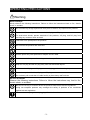
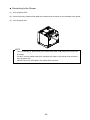
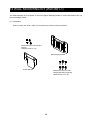
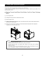
USER’S GUIDE Thermal Printer RP-E10 SERIES Read this user’s guide carefully before using the printer. Keep this user’s guide in a place where it can be accessed quickly. RP-E10 SERIES THERMAL PRINTER USER’S GUIDE Document Number: U00127526501 First Edition: May 2012 Second Edition: July 2012 Copyright 2012 by Seiko Instruments Inc. All rights reserved. The information contained herein is the property of SII and shall not be reproduced in whole or in part without prior written approval of SII. SII reserves the right to make changes in the specifications and materials contained herein without notice and shall not be responsible for any damages (including consequential) caused by reliance on the materials presented, including but not limited to typographical, arithmetic, and listing errors. is a trademark of Seiko Instruments Inc. All other trademarks are the properties of their respective companies. This product complies with EU RoHS Directive(2002/95/EC). Applicable EC Directive and Standards Product: Thermal Printer RP-E10 (with AC adapter PW-E2427-W1) Directive: Title 2004/108/EC EC Electromagnetic Compatibility Directive 2006/95/EC EC Low Voltage Directive (with AC adapter only) Standards EN 55022 EN 61000-3-2 EN 61000-3-3 EN 55024 EN 60950-1 (with AC adapter only) Product: AC adapter PW-E2427-W1 Directive: Title 2004/108/EC EC Electromagnetic Compatibility Directive 2006/95/EC EC Low Voltage Directive Standards EN 55022 EN 61000-3-2 EN 61000-3-3 EN 55024 EN 60950-1 Federal Communications Commission (FCC) compliance statement This equipment has been tested and found to comply with the limits for a Class A digital device, pursuant to part 15 of the FCC Rules. These limits are designed to provide reasonable protection against harmful interference when the equipment is operated in a commercial environment. This equipment generates, uses, and can radiate radio frequency energy and, if not installed and used in accordance with the instruction manual, may cause harmful interference to radio communications. Operation of this equipment in a residential area is likely to cause harmful interference in which case the user will be required to correct the interference at his own expense. Industry Canada (IC) compliance statement Operation is subject to the following two conditions: (1) this device may not cause interference, and (2) this device must accept any interference, including interference that may cause undesired operation of the device. INTRODUCTION Thank you for purchasing the RP-E10 series thermal printer. This MANUAL explains how to handle RP-E10 thermal printer (hereinafter referred to as printer), specified AC adapter, specified AC cable, and other accessories. Read through the "SAFETY PRECAUTIONS" and "OPERATING PRECAUTIONS" carefully before using the printer. Keep this manual in a place where it can be accessed quickly. For more detailed technical information and specifications on the printer, see the "RP-E10 SERIES THERMAL PRINTER TECHNICAL REFERENCE". This manual consists of the following sections. INTRODUCTION ................................................................................. 1 OPERATING PRECAUTIONS............................................................. 5 1 PREPARATION .......................................................................... 7 2 IDENTIFYING THE MODEL TYPE............................................. 9 3 EACH PART OF PRINTER ...................................................... 10 4 POWER CONNECTION ........................................................... 14 5 THERMAL PAPER SETTING................................................... 15 6 ADJUSTMENT OF REMAINING THERMAL PAPER............... 18 7 PREVENTION AND TREATMENT OF PAPER JAM ............... 20 8 TEST PRINT............................................................................. 22 9 FUNCTION SETTINGS ............................................................ 23 10 CONNECTING TO THE HOST DEVICE .................................. 24 11 SETTINGS WHEN USING 58mm PAPER WIDTH .................. 27 12 WALL MOUNTING KIT (WLK-B01-1)....................................... 28 13 PRINTER MAINTENANCE....................................................... 31 14 TROUBLESHOOTING.............................................................. 32 15 SPECIFICATION ...................................................................... 33 16 ACCESSORIES AND CONSUMABLE PARTS ........................ 36 -1- SAFETY PRECAUTIONS The following symbols are used in this Safety Precautions to ensure safe and proper use of products and to alert users. Observe the instructions in the precautions. Warning Failure to follow the instructions marked with this symbol could result in severe personal injury or death. Caution Failure to follow the instructions marked with this symbol could result in minor personal injury or property damage. About symbols The symbol indicates information which you should pay attention to (including danger and warnings). The symbol indicates information about prohibited procedures. indicates “Disassembly is prohibited.” The symbol indicates information about obligated or instructed procedures. indicates ”Unplug the power plug from electric outlet.” -2- OPERATING PRECAUTIONS Warning Never attempt! Strictly observe the following instructions. Failure to follow the instructions leads to fire, electric shock, or accident. Do not insert any foreign objects such as a piece of metal or any liquid into the products. Do not touch the metal parts of the terminal, AC plug, and DC plug. To avoid short circuits, prevent terminals of the products, AC plug, and DC plug from touching any conductor such as metal. Take care not to spill liquid on the products. Do not touch the products with wet hand. Do not disassemble or reconstruct the products. Use the printer only with specified AC adapter and AC cable. Do not use an AC adapter with a voltage other than specified. Keep the AC plug and the DC plug away from dust and metal objects. Make sure the AC plug and DC plug are securely plugged in when using the products. Do not destroy the AC cable, AC plug and DC plug. Do not bend, pull or twist the AC cable forcibly or place heavy staff on them. Be sure to follow! Observe the following instructions. Failure to follow the instructions may lead to fire, electric shock, or accident. Be sure to use only in countries where the products meet the law and the regulations. Using non-compliant products may endanger the safety of products or be considered against law and regulations. Be sure to hold the plug when unplugging AC cable from electric outlet. -3- How to deal with trouble Follow the instructions in the following cases. Failure to follow the instructions may lead to fire, electric shock, and accident. Turn off the printer and unplug the AC plug from the electric outlet in any of the following cases: ♦ ♦ Abnormal status continues. The printer is giving off smoke, an unusual smell, excessive heat, or an unusual noise. ♦ ♦ A piece of metal, water or other foreign objects get into the printer. Case is broken. If AC cable is damaged, unplug the AC plug from electric outlet. Do not use a damaged AC cable. CAUTION Be sure to follow! Observe the following instructions. Failure to follow the instructions may lead fire, electric shock and accident. Turn off the printer and unplug the AC plug when not in use for a long period of time or before maintenance. Do not use or store the products in the following locations: ♦ ♦ Locations subject to direct sunlight or high temperature Locations exposed to high humidity, a lot of dust, and liquid ♦ Unstable locations or locations subject to strong vibration Do not cover the products with cloth when in use. Do not touch the thermal head immediately after printing because it gets hot. Be sure to allow it to cool down before cleaning its head or clearing a paper jam. The auto cutter printer has an exposed cutter blade in the paper eject slot. Do not insert fingers into printer. Avoid touching the exposed blade while the printer cover is open. Keep loose objects such as long hair away from the printer while the printer operates. If they fall into the printer, it may cause personal injury or malfunction. -4- OPERATING PRECAUTIONS Follow the precautions below to deliver and maintain the full performance of the printer. ■ Using the Printer ♦ Be careful not to drop or bump the printer on a hard surface. ♦ DO NOT install the printer in direct sunlight or such areas. Be careful about the ambient temperature and humidity. Suitable environment for the use of the printer is as follows: • Range of the temperature: 5 to 45°C • Range of the humidity: 10 to 90%RH Refer to the technical reference for the allowable humidity range at each temperature. ♦ DO NOT install the printer near devices that generate strong electromagnetic fields such as a copy machine. ♦ DO NOT install the printer in a location that is subject corrosive gas or siloxane and so on. ♦ DO NOT connect the AC cable or the AC adapter to the same outlet with devices that generate noise. ♦ DO NOT open the paper cover during printing or cutting. ♦ DO NOT connect or disconnect the interface cable during printing or transmission. DO NOT touch the connectors of the interface cable during printing. ♦ Turn the power off when not in use. In addition, if the printer is not used for a long time, unplug the AC plug from the outlet, and set thermal paper to protect the platen roller. ♦ Clean the printer case using soft, lint-free cloth. DO NOT use alcohol or other solvent. ♦ Before using, always clean the terminals using a dry, soft, lint-free cloth. If the terminals are dirty, it may not be possible to obtain proper contact. ♦ DO NOT touch the thermal head directly. Doing so may result in poor quality due to the dirt or damage by the static electricity. ♦ DO NOT use the thermal head with getting wet. Doing so may cause the printer damaged. ♦ When cleaning the thermal head, wipe the thermal head with a cotton swab or other soft material. ♦ The AC adapter may become warm when in use. This is normal and is not a malfunction. ♦ High-print-rate printing or using the printer under low temperature condition might cause irregular printouts or generate loud sound. This is not a failure in the printer, but an inherent paper phenomenon. ♦ When handling the printer, be aware of static electricity. If the static electricity is discharged, this could cause a USB communication failure. When this problem occurs, disconnect the USB connector that is connected to the host device and wait a few seconds before connecting it again. ♦ DO NOT print without the thermal paper. ♦ DO NOT drop or insert any foreign objects such as a clip, a pin, or a screw in the internal parts or slot of the printer. ♦ DO NOT drop any liquid or spray a solvent to the printer. ♦ NEVER push the switch on the operation panel using sharp object such as pen tip. -5- ♦ DO NOT use two or more thermal papers which are taped together. ♦ NEVER pull out the thermal paper during the thermal paper setting. ♦ Make sure not to injure your body or other objects by the plate edge. ♦ UNPLUG the DC jack or AC plug from the power outlet if something goes wrong with the printer. ♦ NEVER disassemble the printer without a serviceman. ♦ Be careful not to get your fingers or hands caught in the printer when opening or closing the paper cover. ♦ In order to ensure the function and the safety of the product, be sure to observe the installation direction which is determined for each model. ♦ DO NOT connect the RJ connector to a phone line. It should be used as the drawer kick connector. ♦ NEVER connect a USB cable to the RJ connector. ♦ As the plated sheet steel is used in the printer, the edge face might rust. ■ Thermal Paper Handling ♦ Store the thermal paper in a cool, dry, and dark place. ♦ DO NOT rub the thermal paper with hard objects. ♦ DO NOT leave the thermal paper near organic solvents. ♦ DO NOT allow plastic film, erasers, or adhesive tape to touch the thermal paper for long periods. ♦ DO NOT stack the thermal paper with diazo copies immediately after copying or wet-type copies. ♦ DO NOT use chemical glue. ♦ Always use the specified thermal paper. See "16 ACCESSORIES AND CONSUMABLE PARTS", for details. ■ Precautions on Discarding When discarding used printers, discard them according to the disposal regulations and rules of each respective district. ■ Notations The following two types of notations are used throughout this manual to denote operation precautions and items to remember: NOTE - Operation Precautions This box contains items that, when not followed, may lead to a malfunction or to a deterioration of performance. HINT Items to Remember This box contains helpful hints to remember when using the printer. -6- 1 PREPARATION When you open the carton, make sure it contains the printer and its accessories. Sample thermal paper サンプル感熱紙 本体(上紙排出モデル) Printer (Top paper discharge model) または or 安全上の注意 1枚 SAFETY PRECAUTIONS (one sheet) 58mm紙幅用パーテションプレート 58 mm paper width partition plate 取扱説明書/安全上の注意/各種ソフトウェア User's Guide/SAFETY (CD-ROM) 1枚 PRECAUTIONS/Various Software (CD-ROM, one piece) 58mm紙幅用スペーサプレート 58 mm paper width spacer plate Printer (Front本体(前紙排出モデル) paper discharge model) -7- Models including the AC adapter, AC cable, and interface cable are also available. Keep the package and packing materials for future transportation or long-term storage. The available accessories are shown below. See "2 IDENTIFYING THE MODEL TYPE", for the models. Specified AC cable 指定ACケーブル (the figure shows CB-US03-20A) (図はCB-JP03-20Aを示す) Specified USB cable 指定USBケーブル 指定ACアダプタ Specified AC adapter Specified serial cable 指定シリアルケーブル Wall壁掛け用キット mounting kit -8- 指定Poweredケーブル Specified Powered USB cable 2 IDENTIFYING THE MODEL TYPE The printer model is identified as follows: RP-E10-K3FJ1-U1C3 Direction of paper discharge 0: From the top 1: From the front Case color W: White K: Black Interface S: Serial U: USB E: Ethernet 1: USB + Serial *1 Optional cable included Contact us for details. *1: Serial with power supply pins. When the printer is incorporated into your equipment and then supplied electric power from the equipment, follow the rated value of input voltage for RP-E10 described in the specifications of "15 Printer Specifications", and "RP-E10 SERIES THERMAL PRINTER TECHNICAL REFERENCE", "2.4 Power Supply Specifications". When using a power supply other than the specified AC adapter, use a power supply at your own risk under the safety standard and EMC regulations. -9- 3 EACH PART OF PRINTER 1 2 3 6 4 5 13 7 8 14 11 9 12 Top paper 上面排紙モデル discharge model - 10 - 10 5 12 3 11 14 10 4 6 1 2 9 7 8 13 前面排紙モデル Front paper discharge model 16 18 USBモデル 17 USB model 15 16 16 Serial model シリアルモデル USB + Serial model USB+シリアルモデル - 11 - イーサネットモデル Ethernet model (1) POWER switch (10) Paper width setting knob The POWER switch turns the printer ON or OFF. The LED lights when the printer turns ON. To The knob to set the paper width. It is set to 80 mm by default. When using paper turn the power OFF, hold down the switch for longer than three seconds. with 58 mm width, remove the coin screw, stagger the knob upward, and then fix it with the coin screw again. (2) FEED switch The FEED switch feeds the thermal paper forward. When holding down the switch for a few (11) Thermal head seconds, the printer feeds the thermal paper continuously for the period of held. paper. NEVER touch the thermal head immediately after printing because it is very hot. (3) LED (12) Paper sensor The LED lights when the printer turns ON. See LED Display on the next page for details. The sensor that detects thermal paper existence. The thermal head prints data on the thermal (13) Platen roller Paper port to discharge thermal paper. The The platen roller brings the thermal paper in contact with the thermal head. The platen roller cutter is installed. is turned to feed the paper. (5) Release lever (14) Cutter The lever is used to open the paper cover to set The cutter cuts the thermal paper automatically the thermal paper. after printing. (6) Paper cover (15) Power connector The platen roller is released from the thermal The power connector connects the AC adapter to paper when opening this cover. Open this cover to replace the thermal paper or to clean the this connector. thermal head. (16) Interface connector (7) Paper holder The interface connector connects with the interface cable. (4) Paper outlet The paper holder holds the thermal paper. (17) Drawer kick connector (8) Paper-near-end sensor The paper-near-end sensor detects remaining The connector to connect the drawer. Do not connect a phone line with it. paper amount to replace the thermal paper. (18) Wire clip (9) Paper-near-end sensor setting lever A lever to set the value to detect the remaining The communication cable can be secured to prevent it from being unplugged. amount of the thermal paper. - 12 - LED Display LED Indication Power OFF LED (Color) LED (Lighting Pattern) - Off *1 On*1 Power ON (print-ready) Blue Printing Green On Blue Blink-1 Out-of-paper error Yellow Blink-1 Cover open error Yellow On *2 Paper-near-end Hardware error Red On Head temperature error Violet On Vp voltage error Violet Blink-1 Cutter error Violet Blink-2 Rewriting external flash White Blink-3 Rewriting FW White On *1: Default value *2: When paper-near-end sensor selection (MS5-5) is enabled, LED displays out-of-paper error. Blink Pattern State Pattern 0.2s Blink-1 0.8s 0.1s Blink-2 0.1s 0.7s 0.1s Blink-3 0.1s - 13 - 4 POWER CONNECTION This printer can be powered with an AC adapter. Always refer to "15 SPECIFICATION" before using the AC adapter. ■ Connecting the AC Adapter (1) Connect the AC cable to the AC adapter. (2) Insert the DC jack of the AC adapter to the power connector of the printer. (3) Insert the AC plug of the AC cable to an electric outlet. Pull 引く DCジャックのロック Locking DC jack DCジャックのロック解除 Locking DC jack engaged disengaged ② ③ ① NOTE - The DC jack of the printer power connector has the locking system. To disengage the locking system, pull the DC jack contrary to the arrow in the figure above. Disengage the locking system as described in the figure before connecting or - disconnecting the DC jack. Turn the printer OFF before installing or removing the AC adapter. - If the printer is not used for a long time, unplug the AC cable from the outlet. - 14 - 5 THERMAL PAPER SETTING This printer uses the paper roll (hereinafter referred to as thermal paper). The function settings of the printer depend on the used thermal paper. See "9 FUNCTION SETTINGS", for details. ■ Thermal Paper Setting (1) Pull the release lever to open the paper cover. Top paper discharge model 上面排紙モデル Front paper discharge model 前面排紙モデル (2) Take the glued end from the paper roll. (3) Set the thermal paper directly above the paper holder certainly as the direction shown in the figure. Non-printing side 非印字面 Printing side 印字面 Non-printing side 非印字面 Printing side 印字面 Top paper discharge model Front paper discharge model NOTE - Be careful not to cut your fingers by the cutter blade. - 15 - (4) Pull the thermal paper straight and then push the center of paper cover certainly to close it, to avoid one side lock defect. Top paper discharge model × ○ Front paper discharge model × ○ NOTE - Pull the thermal paper straight. - Push the paper cover certainly to avoid one side lock defect. (5) After closing the paper cover, paper feed and paper cutting are performed automatically. NOTE - Be sure to pull the release lever to the end. If not, the paper cover may not open. DO NOT cover the paper outlet or hold down the thermal paper. Doing so may cause - paper jam. DO NOT touch the platen roller and gears in the printer. Doing so may cause loss of - printing quality or a failure. Always use the paper roll the core of which has 12 mm inside diameter and 18 mm outside diameter. Moreover, DO NOT use the paper roll with glued or taped end. HINT Leaving the printer with the thermal paper that is in the thermal head and platen roller for a long time may cause a paper-feeding error. In that case, open the paper cover to release the thermal head and the thermal paper before using, and then close the paper cover to use it. - 16 - Recommended Thermal Paper Shape × × ○ NOTE - DO NOT use deformed thermal paper. Doing so may cause the printer damaged. × ○ NOTE - In case of using loosened paper roll, rewind the roll before using it. - 17 - 6 ADJUSTMENT OF REMAINING THERMAL PAPER This printer detects remaining amount of the thermal paper by the paper-near-end sensor. Detecting the paper-near-end requires the replacement of the thermal paper with new one. ■ Removing Remaining Thermal Paper (1) Pull the release lever to open the paper cover. (2) Remove the thermal paper from the paper holder. ■ Adjustment of Paper-near-end Sensor The detection value of paper-near-end can be changed according to the following procedure. Set the paper-near-end sensor in accordance with the location of the printer. The default setting is 22±2 mm approx. in diameter (Position A for Top paper discharge models, Position C for Front paper discharge models). NOTE - Use the detection value of paper-near-end as reference. (1) Turn the printer OFF (○ side: hereinafter omitted), and then unplug the DC jack. NOTE - Do not touch the printer when unplugging the DC jack. (2) Move the paper-near-end sensor to the position of A to D while pressing the paper-near-end sensor in the arrow direction in the figure below. Be sure to move the paper-near-end sensor to the correct position until it clicks. NOTE - Be sure to use a paper roll the core of which has 12 mm inside diameter and 18 mm outside diameter. Otherwise, the paper-near-end detection will not work appropriately. - 18 - [Top paper discharge model] 【上紙排出モデル】 Paper-near-end Paper-near-end ペーパニアエンド ペーパニアエンド sensor setting lever センサ設定レバー sensor センサ A B [Front paper discharge model] 【前紙排出モデル】 Paper-near-end Paper-near-end ペーパニアエンド ペーパニアエンド sensor setting lever センサ設定レバー sensor センサ C D Paper-near-end Sensor Position Outside Diameter for Paper-near-end Detection A φ22±2 mm in diameter (Top paper discharge model) B φ25±2 mm in diameter (Top paper discharge model) C φ22±2 mm in diameter (Front paper discharge model) *1 D φ25±2 mm in diameter (Front paper discharge model)*1 *1: Outside diameter for paper-near-end detection is not affected by the installed Wall Mounting Kit (WLK-B01-1). - 19 - 7 PREVENTION AND TREATMENT OF PAPER JAM Do not touch the paper outlet during paper feeding or before paper cutting. Covering the paper outlet or pulling out the paper may cause a paper jam, a cut failure or carriage return malfunction. Never open the paper cover during paper cutting. Do not touch during operation. 動作中は触れないでください Do not touch during operation. 動作中は触れないでください ■ Removing Paper Jam When a paper jam occurs, remove the thermal paper according to the following procedure. (1) Turn the printer OFF. (2) Pull the release lever to open the paper cover, and remove the paper jam. NOTE - Do not damage the printer when removing the thermal paper. Especially, do not touch the thermal head because it is subject to breakage. (3) Set the thermal paper straight and then close the paper cover gently. (4) Turn the printer ON by turning the POWER switch ON. (5) When the printer is recovered, the LED lights in blue. NOTE - NEVER touch the thermal head immediately after printing because it becomes very hot. - 20 - ■ Cutter Error Treatment When the motor is locked during paper cutting due to a cutter error and the paper cover does not open, recover the printer according to the following procedure: (1) Turn the printer OFF. NOTE - Be sure to turn the power off before handling a cutter error. (2) Pull the release lever repeatedly to retract the cutter blade. Then, open the paper cover. When you find a paper jam, remove it. (3) Set the thermal paper straight and then close the paper cover gently. (4) Turn the printer ON by turning the POWER switch ON. (5) When the printer is recovered, the LED lights in blue. NOTE - DO NOT use a ballpoint pen, driver, or box-cutter, etc. to remove a paper jam. Be careful not to damage the printer. Especially, do not touch the thermal head because it is subject to breakage. - Be careful not to cut your fingers or be injured by the cutter. DO NOT apply excessive force on the cutter blade. - 21 - 8 TEST PRINT This printer has a test printing function. In test printing, the function settings of the printer and character strings for testing are printed. (1) Make sure that the thermal paper is set in the printer and the printer is turned off. If the thermal paper is not set, set the thermal paper as instructed in "5 THERMAL PAPER SETTING", and turn the printer OFF. (2) Turn the POWER switch ON while holding down the FEED switch. Release the FEED switch after initializing the printer (the LED lights in blue). (3) Test printing is started. (4) After test printing, the printer cuts the thermal paper. After (1) described below is printed, the LED lights in white and the buzzer sounds. Determine whether or not to enter the function setting mode. [Mode Select] Setting Mode: Feed SW / Normal Mode: Power SW (1) (5) When pressing the POWER switch, (2) described below is printed, and then the LED lights in blue and the buzzer sounds. The function setting mode is cancelled. When pressing the FEED switch, the printer enters the function setting mode. For details, see "9 FUNCTION SETTINGS". Normal Mode Selected (2) - 22 - 9 FUNCTION SETTINGS This printer has various functions which can be preset according to the communication method or the type of thermal paper. The function settings of the printer are stored in the FLASH memory. They are effective until rewriting them again. You can set these functions by using the Memory Switch (hereinafter referred to as MS) 1 to 7 and 13. See "RP-E10 SERIES THERMAL PRINTER TECHNICAL REFERENCE" for details. - 23 - 10 CONNECTING TO THE HOST DEVICE This printer supports the serial, USB, USB + serial, or Ethernet communication, depending on the model, through an interface cable. The function settings of the printer depend on the printer model and the communication method to be used. See "RP-E10 SERIES THERMAL PRINTER TECHNICAL REFERENCE". A separate interface cable is required for the serial, USB, or Ethernet communication. See "15 SPECIFICATION", for details of interface specifications. The communication speed might be reduced depending on data processing by software as well as print type and size. ■ Serial/USB/Ethernet Communication Through Interface Cable (1) Turn the printer OFF. (2) Connect the interface cable to use to the interface connector on the backside of the printer. (When connecting a USB cable, lock the cable with the wire clip as shown in the figure below.) (3) Turn the printer ON and send data from the host device to the printer. (4) Verify that the data is printed correctly. Wire clip ワイヤクリップ Locking USB interface cable and USB cable Serial interface cable - 24 - Ethernet interface cable NOTE - When connecting an interface cable to the interface connector, push it until it clicks. - DO NOT connect plugs of other cables including drawer kick cable or phone line to the interface connector. - When connecting an outdoor aerial-wired LAN cable, be sure to use it through another anti-serge device. Otherwise, the device may be damaged by induced lightning. - 25 - ■ Connecting to the Drawer (1) Turn the printer OFF. (2) Connect the plug of drawer kick cable to the drawer kick connector on the backside of the printer. (3) Turn the printer ON. NOTE - When connecting or disconnecting the drawer kick cable, hold the plug and never pull the cable. DO NOT connect cables other than a drawer kick cable to the drawer kick connector, - such as phone line. NEVER connect a USB cable to the drawer kick connector. - 26 - 11 SETTINGS WHEN USING 58mm PAPER WIDTH (1) Turn the printer OFF. (2) Pull the release lever to open the paper cover. (3) Remove the coin screw of the paper width setting knob at the Position A, move the knob to the Position B, and then fix it with the coin screw again. A B (4) Set the accompanying partition plate and the spacer plate to the position as shown in the figure. See "RP-E10 SERIES THERMAL PRINTER TECHNICAL REFERENCE" to set the paper width (MS2-6) to 58 mm. NOTE - Set the paper width before using the printer for the first time. Do not change the paper width after starting to use the printer. - 27 - 12 WALL MOUNTING KIT (WLK-B01-1) The Wall Mounting Kit is exclusive for the Front paper discharge model. It cannot be used for the Top paper discharge model. (1) Preparation When you open the carton, make sure it contains the product and its accessories. プリンタ取り付けねじ 4本 Printer attachment screw (four pieces) (タッピングねじ3×6) (Tapping screw 3 x 6) Wall hanging bracket ウォールハンギングブラケット Printer bracket プリンタブラケット Attachment screw for wall ウォールハンギングブラケット取 り付けねじ 6本 hanging bracket (six pieces) (木ねじ3.8×18) 壁掛け用キット(Wood screw 3.8 x 18) - 28 - (2) Installation of Printer Bracket Fix it with four attachment screws certainly as shown in the following figure. The tightening torque should be 39.2 cN•m (4 kgf•cm). NOTE - Turn the printer OFF before installation. Remove the AC cable of the AC adapter and the interface cable. (3) Installation of Wall Hanging Bracket Fix the wall hanging bracket to the mounting surface, and then secure it with six attachment screws for the bracket. WLK-B01-1 is designed to be installed on a wall. After installation, make sure that the wall hanging bracket is fixed on the wall securely without rattle. NOTE - The accompanying attachment screws for wall hanging bracket are for installing to wood materials. Do not use them for other materials. - 29 - (4) Installation of the Printer Slide the printer into the wall hanging bracket from the top to the bottom to insert the printer bracket into the wall hanging bracket, as shown in the figure. NOTE - Check the place and the material/structure of the wall, and then install the printer securely. Injury or destruction of property might occur by dropping off. - 30 - 13 PRINTER MAINTENANCE The thermal head of this printer does not require user maintenance. If paper powder accumulates, clean the thermal head to maintain maximum print quality for an extended period of time. ■ Cleaning Thermal Head/Platen Roller/Rubber Feet(Front Paper Discharge Model) (1) Turn the printer OFF. (2) Unplug the AC plug of the AC cable from the outlet. (3) Open the paper cover. (4) Clean the thermal head, the platen roller, or the rubber feet with a cotton swab moistened with a small amount of ethyl alcohol. (5) Wait until any ethyl alcohol remaining on the thermal head and the platen roller evaporates completely, then close the paper cover. NOTE - Clean the thermal head after it cools. Wipe the thermal head with a cotton swab or other soft material. - DO NOT touch the gear of the platen roller. Doing so may cause loss of printing quality or a failure. - The rubber feet have the special adsorption structure. They lose adsorption force as dust or dirt adheres. However, it can be recovered by cleaning. - 31 - 14 TROUBLESHOOTING Check the following points before requesting for repair: ■ The power does not turn ON • • Is specified AC adapter being used? Are the AC cable and AC adapter connected correctly? • Is the AC adapter connected to the printer correctly? ■ The printer does not print • • Is the interface cable connected correctly? Is the specifications of interface cable conformed to its specifications of this manual being used? • • Is the communication method between the printer and the host device correct? Is specified thermal paper being used? Is the paper orientation (surface/back) correct? ■ An error is displayed • • See "LED Display" on page 13. Is the function settings of the printer correct? - 32 - 15 SPECIFICATION ■ Printer Specifications Item Specification Model RP-E10, RP-E11 Printing method Characters per line *1 Thermal Paper width 80 mm: 24 dots x 12 dots 48 (42 *2 ) 16 dots x 8 dots 72 (64 *2 ) Paper width 58 mm: 24 dots x 12 dots 36 (30 *2 ) 16 dots x 8 dots 54 (45 *2 ) Character size (H x W) One-byte: H24 dots x W12 dots, H16 dots x W8 dots Two-byte: H24 dots x W24 dots, H16 dots x W16 dots Number of effective dots Paper width 80 mm: 576 dots (512 dots *2 ) Paper width 58 mm: 432 dots (360 dots *2 ) Dot density 8 dots/mm Paper width/Printing width 80 mm/72 mm 58 mm/54 mm Printing speed 350 mm/s max. Paper cutting method Slide cutting Paper cutting type Full cut, Partial cut (remaining the center dot) Operating temperature 5 to 45 °C Relative humidity *3 (80 mm/64 mm *2 ) (58 mm/45 mm *2 ) 10 to 90 %RH Dimensions (W x D x H) 129 x 129 x 129 mm *4 Mass Approx. 1.3 kg (excluding the thermal paper) Input voltage DC24.0 V ±5% *1: One-byte character, character spacing is 0 dot *2: When selecting 512/360 dots by MS4-5 *3: Refer to the technical reference for the allowable humidity range at each temperature *4: Excluding projections ■ Specified AC Adapter Specifications Item Specification Model PW-E2427-W1 Input voltage AC100 to 240 V, 50/60 Hz Rated output DC24.0 V, 2.71 A Dimensions (W x D x H) 115 x 35 x 38 mm *1 Mass Approx. 330 g *1: Excluding cable - 33 - (Accessories) ■ Interface Specifications Serial interface specifications Item Specification Synchronous Asynchronous Baud rate 9600, 19200, 38400, 115200 bps Data length 7 or 8 bits Parity None, Even or Odd Data control Hardware control, Xon/Xoff USB interface specifications Item Specification Version Ver 2.0 conformity Printer data transmission mode Bulk transfer (12 Mbps) Ethernet interface specifications Item Specification Communication standard 10Base-T/100Base-TX - 34 - ■ Compliance Table Check the list below to see if the printer and its accessories can be operated in destination countries and comply with the regulations. ○: Compliant RP-E10 PW-E2427-W1 *2 (Specified AC adapter) Japan ○ ○ USA ○ ○ Canada ○ ○ Mexico ○ ○ EU, EFTA ○ ○ Russia ○ ○ Australia, New Zealand ○ ○ Countries *1 *1: Ask your SII sales representative if you want to operate the products in other countries than listed above. *2: The compliant AC cable differs from country to country. See the list below to find out which cable you need to connect in destination countries. ■ Specified AC Cable Table For Specified AC Adapter (PW-E2427-W1) Countries Model*1 Manufacturer Japan CB-JP03-20A SII USA, Canada, Mexico CB-US03-20A SII EU (except United Kingdom), EFTA, Russia CB-CE03-20A SII United Kingdom CB-UK02-20A SII Australia, New Zealand CB-AU02-20A SII *1: Use the model only in the countries in the list. - 35 - 16 ACCESSORIES AND CONSUMABLE PARTS ■ Accessories Name Model Specified AC adapter PW-E2427-W1 *1 Specified AC cable For Japan For USA, Canada, Mexico For EU (except United Kingdom), EFTA, Russia For United Kingdom For Australia, New Zealand CB-JP03-20A CB-US03-20A CB-CE03-20A CB-UK02-20A CB-AU02-20A Wall mounting kit WLK-B01-1 USB cable Serial cable Powered USB cable IFC-U02-1 IFC-S02-1 IFC-V01-1 *1: The shape of the power outlet differs in countries. Confirm it before using. ■ Specified Thermal Paper*1 Model Manufacturer TF60KS-E Nippon Paper Industries Co. PD160R Oji Paper Co., Ltd. F220VP Mitsubishi Paper Mills., Ltd. P220VBB-1 Mitsubishi Paper Mills., Ltd. F5041 Mitsubishi Hi-Tech Paper KT48FA Koehler Alpha400-2.1 Appleton Alpha820-3.4 Appleton *1: We do not offer thermal paper. If using thermal paper that is not specified, quality of printing or specified life span of the thermal head would not be guaranteed. - 36 - Seiko Instruments Inc. 1-8, Nakase, Mihama-ku, Chiba-shi, Chiba 261-8507, Japan Print System Division Telephone:+81-43-211-1106 Facsimile:+81-43-211-8037 Seiko Instruments USA Inc. Thermal Printer Div. 21221 S. Western Avenue, Suite 250, Torrance, CA 90501, USA Telephone:+1-310-517-7778 Facsimile:+1-310-517-7779 Seiko Instruments GmbH Siemensstrasse 9, D-63263 Neu-lsenburg, Germany Telephone:+49-6102-297-0 Facsimile:+49-6102-297-222 Seiko Instruments (H.K.) Ltd. 4-5/F, Wyler Center 2,200 Tai Lin Pai Road, Kwai Chung, N.T., Kowloon, Hong Kong Telephone:+852-2494-5160 Facsimile:+852-2424-0901 (Specifications are subject to change without notice.)