1
Electronic Total Stations
DTM-350
Model DTM-330
Model
Instruction Manual
Thank you for purchasing the Nikon products. This
instruction manual was written for the users of the
Electronic Total Station DTM-350/330. To ensure
correct usage read this manual carefully before
operating the instrument.
Also read the Instruction Manual provided with the
Battery Charger and any other equipments used
together with the DTM-350/330.
Warning and Caution
Symbols in This Manual
Though Nikon products are designed to provide
you utmost safety during use, incorrect usage or
disregard of the instructions can cause personal
injury or property damage. For your safety, read the
instruction manual carefully and thoroughly before
usage. Do not discard this manual but keep it near
the product for easy reference.
Inside this instruction manual, safety instructions are
indicated with the symbols shown below. Be sure to
follow the instructions marked with these symbols for
your safety.
WARNING
Disregarding instructions marked with this
symbol may lead to death or serious injury.
CAUTION
Disregarding instructions marked with this
symbol may lead to injury or property damage.
i
WARNING AND CAUTION
Read This Section Before Use!
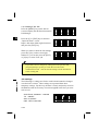
WARNING
Never see the sun through the telescope. Doing so may cause
the loss of your eyesight.
The DTM-350/330 does not feature explosion-protected
construction. Do not use in coal mines, in areas contaminated
with coal dust, or near other flammable substances.
Never disassemble, modify or repair the instrument. Doing so
may cause fire, electric shock or burn.
Use only the specified charger Q-75U/E for charging the battery
pack BC-65. Charging by the other types of chargers than
specified may cause fire or rupture. (BC-65 can not be charged
by using the charger Q-7U/E or Q7C.)
While recharging the battery pack, do not cover the charger with
any blanket or clothing which can cause overheating. Make sure
the charger is able to dissipate heat adequately. Especially, do not
block its air holes while recharging. If so, the gas will remain in the
battery pack and may cause rupture.
Avoid recharging in humid or dusty places, in direct sunlight, and
near heaters. Do not recharge when wet. Doing so may cause
electric shock, overheating or fire.
Although the battery pack BC-65 is equipped with an auto-reset
circuit breaker, care should be taken not to short the contacts.
Shorting may cause fire or burn.
Never burn or heat the battery. Doing so may cause rupture or
injury.
When storing the battery pack or charger, guard against a short
circuit by putting the insulating tape on the contact point or by
doing some other methods. Failure to do so may result in a short
circuit, causing a fire, burn or instrument damage.
The battery BC-65 is not designed to be waterproof by itself. Do
not wet the battery with removed from the instrument. Doing so
may cause fire or burn.
ii
WARNING AND CAUTION
Read This Section Before Use!
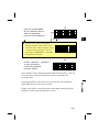
CAUTION
The top of the tripod ferrule is very sharp and may injure your
body. Be careful in handling or carrying the tripod.
Check the shoulder strap and its clasp before carrying the tripod
or the instrument encased in the carrying case. Damaged strap or
imperfect clasping may cause an accident of falling.
Before setting up the tripod, check below to make sure no one’s
hands or feet are in the way. Failure to do so may result in injury if
hands or feet should be pierced by the legs of the tripod.
Fasten firmly the thumb screws of the tripod legs after mounting
the instrument on the tripod. If not, the tripod may collapse,
resulting in injury or instrument damage.
Be sure to fasten the clamp screw on the tripod securely after
installing the instrument on the tripod. Failure to do this may
cause the instrument to fall, resulting in injury or instrument
damage.
Fasten securely the leveling base clamp knob. If the knob is not
securely fastened, the leveling base may fall when you grasp the
carrying handle, resulting in injury or instrument damage.
Do not stack up the plastic carrying case and do not use it as a
stool. Plastic carrying case is slippery and unstable. Doing things
like this may cause an accident and result in personal injury or
instrument damage.
Do not swing or throw the plumb bob. It may hit and injure the
other person.
Be sure to read the instructions of Quick Charger Q-75U/E before
starting charging operation.
iii
MAINTENANCE
Read This Section Before Use!
Avoid prolonged exposure to the sun or the heat of a closed
vehicle. Efficiency could be adversely affected.
If the instrument has been used in wet conditions, incline the
instrument so as to remove the water drops out of the concave
parts on the instrument. Wipe off any moisture on the instrument
and dry it completely before replacing it in its carrying case. The
instrument contains many sensitive electronic assemblies which
have been well protected against dust and moisture. However,
should dust or moisture be introduced into the instrument, severe
damage could result.
Sudden changes in temperature may cloud the lenses and
drastically reduce the measurable distance, or initiate an electrical
system failure. Should this occur, leave the instrument in a warm
location with the case closed until the temperature of the
instrument returns to room temperature.
Avoid storing the instrument in hot humid locations. Especially, the
battery pack should be stored in a dry location at a temperature of
less than 30°C. Higher temperature and excessive humidity may
result in growth of mold on the lenses and deterioration of the
electronic assemblies, leading to instrument failure.
Store the battery pack with the battery discharged.
When storing the instrument in areas subject to extremely low
temperature, leave the carrying case open.
Do not overtighten any of the clamp screws.
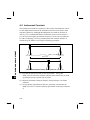
When adjusting the vertical and upper plate tangent screws or the
leveling screws, stay as close as possible to the center of the
screw’s range, as indicated by a line on the screw.
Use a clockwise rotation of the tangent screws for final
adjustment.
If the leveling base is to be left unused for an extended period,
lock-down the leveling base clamp knob and tighten its safety
screw.
iv
MAINTENANCE
Read This Section Before Use!
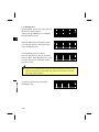
Do not use organic solvents (such as ether or paint thinner) to
clean the non-metallic parts such as the keyboard, and the
painted or printed surfaces. Doing so could result in discoloration
or in the peeling of printed characters. Clean only with a soft cloth
or tissue lightly moistened with water or mild detergent.
Optical lenses may be cleaned by lightly wiping them with a soft
cloth or lens tissue moistened with alcohol.
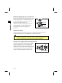
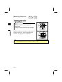
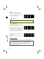
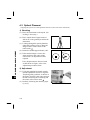
Do not release the reticle plate
cover, and do not subject it to
undue force, as this cover has
been appropriately mounted.
Doing so could adversely affect
the watertight structure of the
unit.
Reticle plate cover
Before attaching the battery pack, first make sure that the surface
where the battery pack attaches is clear of foreign matter, and
then press the battery pack into place until the battery mounting
button rises up to the battery pack top surface. If the battery pack
is not attached securely, it could adversely affect the watertight
structure of the unit.
Press the cap for data output/external power input connector until
it clicks into place. If this cap is not attached securely, it could
adversely affect the watertight structure of the unit.
Do not leave the carrying case exposed to rain for an extended
period of time, though it is designed to be watertight. If you
expose the carrying case to rain because of unavoidable
circumstances, place it with its “Nikon” nameplate upward.
The BC-65 battery pack holds Ni-MH inside. Be sure to follow the
laws or rules of your municipal waste system when disposing of it.
v
Contents
Warning and Caution Symbols in This Manual ................... i
Read This Section Before Use!............................................ ii
WARNING AND CAUTION......................................................................ii
MAINTENANCE ......................................................................................iv
1. NOMENCLATURE .......................................................... 1-1
2. PREPARATION............................................................... 2-1
2-1
2-2
2-3
2-4
2-5
2-6
2-7
2-8
Unpacking and Packing the Instrument ....................................... 2-1
Recharging and Connecting the BC-65 Battery Pack.................. 2-2
Setting up the Tripod.................................................................... 2-6
Centering...................................................................................... 2-7
Leveling ........................................................................................ 2-9
Sighting ...................................................................................... 2-10
Assembling the Prism Reflector ................................................. 2-11
Face-left/Face-right Measurement............................................. 2-13
3. OPERATION ................................................................... 3-1
3-1
3-2
3-3
3-4
Display and Key Functions........................................................... 3-1
Pre-Start ....................................................................................... 3-5
Getting Started ........................................................................... 3-14
Applications ................................................................................ 3-30
4. CHECKING AND ADJUSTMENT.................................... 4-1
4-1
4-2
4-3
4-4
Plate Level.................................................................................... 4-1
Circular Level ............................................................................... 4-1
Optical Plummet........................................................................... 4-2
Zero Point Errors of Vertical Scale
and Horizontal Angle Corrections ................................................ 4-3
4-5 Instrument Constant..................................................................... 4-6
vi
5. SPECIFICATIONS........................................................... 5-1
5-1 Main Body .................................................................................... 5-1
5-2 Standard Components ................................................................. 5-4
5-3 External Device Connection Connector ....................................... 5-4
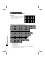
6. SYSTEM DIAGRAM ........................................................ 6-1
1
2
3
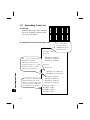
7. COMMUNICATIONS ....................................................... 7-1
7-1 Upload Coordinate Data.............................................................. 7-1
7-2 Uploading Code List.................................................................... 7-3
7-3 Downloading Data....................................................................... 7-5
8. ERROR MESSAGES AND ACTIONS............................. 8-1
4
5
6
7
8
vii
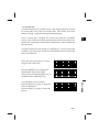
NOMENCLATURE
1
1. NOMENCLATURE
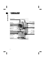
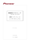
Carrying handle
Telescope
focusing ring
Telescope
eyepiece
Diopter ring
Reticle plate
cover
Plate level
Display
Face-left keyboard
Refer to p.3-1, p.3-2
and p.3-3 for the key
arrangement and its
major function.
Leveling base
clamp knob
1-1
Battery mounting
button
Battery pack
BC-65
Vertical clamp
Vertical tangent
screw
Upper plate
clamp
Upper plate
tangent screw
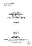
NOMENCLATURE
1
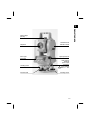
Optical sight
(Finder)
Objective
Face-right
keyboard
Leveling base
Circular level
Horizontal axis
indication mark
Optical plummet
Data output/
External
power input
connector
Input voltage
DC 7.2 – 11V
Leveling screw
1-2
NOMENCLATURE
1
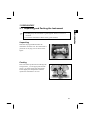
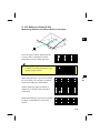
2. PREPARATION
2-1 Unpacking and Packing the Instrument
y Handle gently the instrument to guard against shocks or excessive
vibration.
y Encase the instrument with the battery pack attached.
PREPARATION
)
2
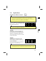
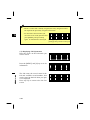
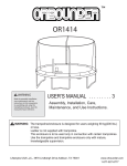
Unpacking
Hold the carrying-handle and take the
instrument out of the case. The instrument is
placed in its carrying case as shown in the
figure.
Packing
Direct the telescope downward and align the
storage mark (t) on the upper plate and the
mark (t) on the leveling base clamp knob.
Fasten lightly the clamp knobs and then
replace the instrument in its case.
2-1
2-2 Recharging and Connecting
the BC-65 Battery Pack
2
PREPARATION
WARNING
Use only the specified charger Q-75U/E for charging the battery
pack BC-65. Charging by the other types of chargers than
specified may cause fire or rupture. (BC-65 can not be charged by
using the charger Q-7U/E or Q-7C.)
While recharging the battery pack, do not cover the charger with
any blanket or clothing which can cause overheating. Make sure
the charger is able to dissipate heat adequately. Especially, do not
block its air holes while recharging. If so, the gas will remain in the
battery pack and may cause rupture.
Avoid recharging in humid or dusty places, in direct sunlight, and
near heaters. Do not recharge when wet. Doing so may cause
electric shock, overheating or fire.
Although the battery pack BC-65 is equipped with an auto-reset
circuit breaker, care should be taken not to short the contacts.
Shorting may cause fire or burn.
Never burn or heat the battery. Doing so may cause rupture or
injury.
When storing the battery pack or charger, guard against a short
circuit by putting the insulating tape on the contact point or by
doing some other methods. Failure to do so may result in a short
circuit, causing a fire, burn or instrument damage.
The battery BC-65 is not designed to be waterproof by itself. Do
not wet the battery with removed from the instrument. Doing so
may cause fire or burn.
CAUTION
Be sure to read the instructions of Quick Charger Q-75U/E before
starting charging operation.
2-2
y Recharge the battery pack indoors within an ambient temperature
range 0°C to +40°C. Charging outside this temperature range will
trigger a protective circuit which prevents normal recharging.
2
y Keep the charging plug clean to prevent misoperation.
PREPARATION
)
y If the charging indicator blinks whenever charging starts, there is an
error in the battery pack. Stop using the battery pack and contact your
dealer or a Nikon representative.
y If the battery pack is recharged within the specified ambient
temperature range and the charging indicator stays lit for 4 hours or
longer, something is wrong. Contact your dealer or a Nikon
representative. (If an ambient temperature lowers than 0°C while
recharging the battery, the charger’s temperature sensor will stop the
charging operation. In such a case, it is normal for the charging
indicator to stay lit for 4 hours or longer. If the ambient temperature
increases to above 0°C, the quick charge operation will restart and the
charging will be completed within 3 hours.)
y After recharging the battery pack, do not recharge it again before using
or discharging it. This is to prevent the battery pack’s performance
from degrading.
y During the quick charging or discharging operation, the battery pack
and quick charger will become warm. This is normal.
y Temperatures of less than approx. -20°C will reduce the battery
capacity. This will result in a shortened working life compared to
operation at a normal temperature.
y The battery pack left disused for a long period might not be fully
recharged. In such a case, charge and discharge the battery pack
several times to restore its full recharging potential.
y BC-65 can be charged by using the charger Q-70U/E or Q-70C, but
not be fully charged.
2-3
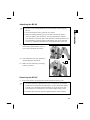
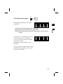
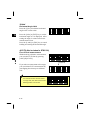
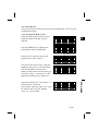
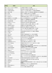
Recharging Procedure
PREPARATION
2
(1) Insert the power plug of charger into
an AC outlet.
To AC outlet
Charging
indicator
Disharging
indicator
Disharging
starting
switch
(2) Connect the charging plug to the
battery pack’s charging connector.
(3) Quick charging will then start
automatically. Check that the
charging indicator lights.
Air holes
(4) When charging is completed, the
charging indicator goes out.
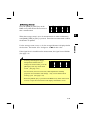
Discharging Procedure
(1) Insert the power plug into an AC outlet.
(2) Connect the charging plug to the battery pack’s charging connector.
(3) Press the discharge starting switch to start discharging. Check that the
discharging indicator will light.
(4) When discharging is completed, the discharging indicator goes out and quick
charging starts automatically. During charging, the charging indicator lights.
)
y To stop discharging before completion, press the discharge starting
switch again. The discharging will stop and quick charging will start
automatically. During quick charging the charging indicator lights.
y Discharging the battery pack once every 10 recharging cycles is
effective.
Discharging Operation
The battery pack is designed for repetitive recharging and use. However, if
the battery pack is recharged while it still has enough power to operate the
surveying instrument, the battery power will last for shorter periods.
(Memory effect) In such a case, discharging the battery pack first can
refresh its capacity for normal performance.
2-4
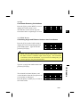
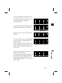
Attaching the BC-65
y Be sure to turn off the [PWR] key before attaching or detaching the
BC-65.
2
y Avoid touching the battery pack BC-65 contacts.
y Before attaching the battery pack, first make sure that the surface
where the battery pack attaches is clear of foreign matter, and then
press the battery pack into place until the battery mounting button rises
up to the battery pack top surface. If the battery pack is not attached
securely, it could adversely affect the watertight structure of the unit.
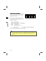
(1) Align the two projections at the bottom
of the battery pack with the concave
parts of the instrument main body.
1
(2) Attach the battery pack by pushing in
while holding the instrument.
2
(3) Make sure that the battery mounting
button is released.
Detaching the BC-65
(1) Depress the battery mounting button while holding the battery pack.
)
y An external battery (optional accessory) is available for use with the
DTM-350/330. When the external battery is connected and the battery
pack BC-65 is mounted on the instrument, its electrical source will
automatically be switched to the one with the higher battery power.
y Read also the instruction manual supplied with the external battery.
2-5
PREPARATION
)
2-3 Setting up the Tripod
PREPARATION
2
CAUTION
The top of the tripod ferrule is very sharp and may injure your
body. Be careful in handling or carrying the tripod.
(1) Open the tripod legs sufficiently enough for the instrument to be stable.
(2) Assure that the station point is located directly beneath the center hole in the
tripod head.
(3) Firmly press the tripod ferrules into the ground.
(4) Level the top surface of the tripod head.
)
y Precise level is necessary when the plumb bob is used for the next
section “centering”.
(5) Fasten firmly the thumb screws on the tripod legs.
(6) Place the instrument on the tripod head. Insert the tripod mounting screw into
the center hole of the instrument base plate and tighten.
)
2-6
y Do not carry the instrument while it is attached to a tripod.
2-4 Centering
Using Plumb Bob
(1) Place the instrument on the tripod head. Insert the tripod mounting screw into
the center hole of the instrument’s base plate and tighten.
(2) Hang the plumb line on the hook of the tripod mounting screw and adjust the
length of the plumb line to the position the tip of the plumb bob at the height
approximately level with the station point.
(3) Slightly loosen the tripod mounting screw. Supporting the outer side of the
leveling base with both hands, carefully slide the instrument about on the
tripod head until the tip of the plumb bob is perfectly positioned over the
center of the station point.
)
y Confirm precise alignment by viewing from two directions at right
angles to each other.
2-7
2
PREPARATION
“Centering” refers to the precise alignment of the instrument’s central axis over the
station point. This can be accomplished in two ways, through the use of a plumb
bob, or the optical plummet.
Using Optical Plummet
PREPARATION
2
)
y Carry out the “CHECKING AND ADJUSTMENT of Optical
Plummet” (p.4-2) when the centering operation is performed at a
position higher than the station point.
y For high accuracy, carry out the “CHECKING AND ADJUSTMENT
of Optical Plummet” (p.4-2) before the centering operation.
(1) Place the instrument on the tripod head.
Insert the tripod mounting screw into the
center hole of the instrument’s base plate
and tighten.
(2) Looking through the optical plummet,
align the station point image with the
center mark
of the reticle by turning
the leveling screws.
(3) While supporting the tripod head with one
hand, loosen the tripod leg clamps and
adjust the lengths of the legs to center the
air bubble in the circular level. Then tighten
the tripod leg clamps.
(4) Using the plate level proceed to the leveling
procedures described in the next section
“Leveling”.
(5) Looking through the optical plummet,
reconfirm that the station point image is still
centered in the reticle mark .
(6) If the slight displacement is detected, loosen
the tripod mounting screw and correct the
instrument’s positioning with direct
movement (not rotational). If the
displacement is major, repeat Steps from (2).
2-8
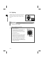
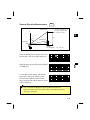
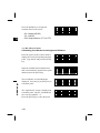
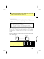
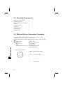
2-5 Leveling
(1) Loosen the upper plate clamp. Rotate the
alidade to position the plate level to a point
parallel with any two of the leveling screws
B and C (See Figure).
A
B
C
(2) Using these two screws, move the bubble to
the center of the level.
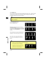
(3) Rotate the alidade approximately 90° and
again move the bubble to the center of the
level by turning the leveling screw A, as
shown in Figure.
(4) Repeat Steps (1) through (3) to center the
bubble in both positions shown by the
Figures.
1
A
B
2
PREPARATION
“Leveling” refers to the precise vertical alignment of the instrument’s vertical axis.
The procedure for leveling by means of the plate level is described below.
C
2
(5) Furthermore, rotate the alidade 180°. If the
bubble in the plate level remains centered,
leveling is complete.
(6) If the bubble moves off center, refer to p.4-1
“CHECKING AND ADJUSTMENT of Plate
Level” and adjust the plate level.
2-9
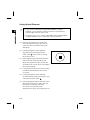
2-6 Sighting
PREPARATION
2
“Sighting” refers to the aiming of the telescope at
the target, bringing the target image into focus,
and aligning it with the center crosshairs of the
reticle.
WARNING
Never view the sun through the telescope. Doing so may cause
the loss of your eyesight.
Notes on sighting are as follows:
)
y Diopter Adjustment
Direct the telescope towards a blank area,
such as the sky or a piece of paper.
Looking through the eyepiece, rotate the
diopter ring to bring the reticle crosshairs
into sharp focus.
y Elimination of Parallax
Rotate the focusing ring to bring the target
image into focus on the reticle crosshairs.
Move your eye vertically and laterally to
see if the target image moves in relation to
the reticle crosshairs. If the target image
does not move, there is no parallax. If it
moves, rotate the telescope focusing ring to
eliminate the parallax.
2-10
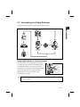
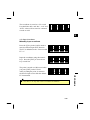
2-7 Assembling the Prism Reflector
Assemble the prism reflector referring to the Figure below.
2
PREPARATION
Target pole
Target plate for single prism
Tribrach adapter
Prism
Leveling base W10
Tiltable single
prism holder
Triple prism holder
Tripod
Height Adjustment of Tribrach Adapter
Tribrach adapter can be adjusted to two heights
by sliding up and down the prism holder mount.
To change the height, first remove the height
adjustment screw from the tribrach adapter. Slide
the prism holder mount to align the height
adjustment screw holes and screw in the
adjustment screw again.
)
Prism holder mount
Height adjustment
screw
y When using the DTM-350/330, set the prism holder mount to the
lower position.
2-11
Direction Adjustment of the Prism
PREPARATION
2
The prism mounted on the tribrach adapter can be
faced in any direction on the horizontal surface.
To change the direction, release the rotation
clamp by turning the clamp lever
counterclockwise. Turn the upper plate of the
tribrach adapter so that the prism faces the
desired direction. Turn the clamp lever
clockwise.
Clamp
Clamp lever
Unclamp
Prism Constant
Attach the prism to the single prism holder or triple prism holder. The prism
constant of Nikon prism is 0, regardless of the prism holder type.
y The triple prism holder can also be used as a single prism holder if one
prism is screwed in the center thread of the triple prism holder.
Position of Target Plate for Single Prism
Attach the target plate to the single prism holder
using the supplied two set screws. Within the
range of screw hole, adjust the position of the
target plate so that the apex of the wedge pattern
of the target plate will come into line with the
centers of the tribrach adapter and the prism.
2-12
Center on axis
2-8 Face-left/Face-right Measurement
)
y Be careful not to catch your finger in the opening between the
instrument’s standard and the telescope when rotating the telescope.
y Mechanical constant error (except in some special cases such as vertical
axis error) can be effectively cancelled out by averaging the
measurement values obtained in face-left and face-right measurements.
Therefore, both measurement methods should be used whenever
possible.
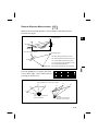
Face-left measurement
Face-right measurement
2-13
2
PREPARATION
Face-left Measurement: Measurements made with the vertical circle positioned to
the left of the telescope eyepiece
Face-right Measurement: Measurements made with the vertical circle positioned to
the right of the telescope eyepiece
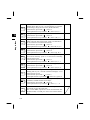
CONTENTS
3 OPERATION............................................................................3-1
3
3-1 DISPLAY AND KEY FUNCTIONS .............................................. 3-1
OPERATION
Basic Measurement Screen (BMS).................................................. 3-4
3-2 PRE-START ................................................................................... 3-5
Input Point Name/Number.............................................................. 3-5
1) Pressing the [ENT] without a PT ....................................................... 3-5
2) Inputting a new PT ............................................................................. 3-6
3) Inputting a known PT ......................................................................... 3-6
4) When a wildcard (*) is specified.......................................................... 3-7
How to Input a Code ........................................................................ 3-8
1) Manual Input....................................................................................... 3-8
2) Stack Input .......................................................................................... 3-8
3) Code List .............................................................................................. 3-9
4) Qcode.................................................................................................. 3-10
How to Input the Feet-Inches on the Instruments ...................... 3-11
List Displays................................................................................... 3-12
About Jobs ...................................................................................... 3-13
3-3 GETTING STARTED................................................................... 3-14
PWR
Turn On the Instrument ................................................................ 3-14
PWR
ENT
Turn Off the Instrument ..............................................................
3-16
○
A
G
MSR B
TRK H
Measuring Distances......................................................................
3-17
1 ○C
3 ○I
1) Sighting a prism reflector ................................................................. 3-17
2) Measuring distances ......................................................................... 3-18
3) Measurement mode settings ............................................................. 3-19
D
DSP E
Switching between Screens ...........................................................
3-20
2 ○F
i
MODE
Mode Key ........................................................................................ 3-23
1) While Inputting PT/CD ..................................................................... 3-23
2) Quick Code Mode (from BMS) .......................................................... 3-24
HOT
M
N
HOT Key .........................................................................................
3-25
5 ○O
2) Temperature & Pressure .................................................................. 3-25
3) MSR/TRK Key Settings..................................................................... 3-25
4) Level................................................................................................... 3-26
5) Qedit................................................................................................... 3-26
6) Qmode ................................................................................................ 3-27
LCD Backlight and Sound On/Off................................................. 3-28
1) Backlight............................................................................................ 3-28
2) Sound ................................................................................................. 3-28
*
XYZ /
Simple Station input (XYZ-key) ....................................................
3-29
0 ○=
3-4 APPLICATIONS .......................................................................... 3-30
ANG
J
K
HA Reset and Measurements ........................................................
3-30
4 ○L
P
RDM Q
Remote Distance Measurement ....................................................
3-34
6 ○R
S
REM T
Remote Elevation Measurement ...................................................
3-36
7 ○U
V
STN W
Instrument Station Setup..............................................................
3-37
8 ○X
1) Known ................................................................................................ 3-37
2) Multiple Resection............................................................................. 3-41
3) Quick Station (Quick)........................................................................ 3-46
4) Remote Benchmark (RBM) ............................................................... 3-47
5) BS Check (BS Chk)............................................................................ 3-48
ii
3
OPERATION
1) Height of Target ................................................................................ 3-25
S-O Y
Staking out .....................................................................................
3-49
9 ○Z
1) Ang-Dist (HD-HA) ............................................................................. 3-49
2) XYZ .................................................................................................... 3-52
3) 2-Pt Reference Line (2REF) .............................................................. 3-56
4) 2-Pt Reference Plane (V-Pln) ............................................................ 3-58
3
5) 3-Pt Reference Plane (S-Pln)............................................................. 3-60
OPERATION
6) Arc-curve Reference Line (Arc)......................................................... 3-62
REC
.
–
Recording Measurement Data.......................................................
3-64
.○+
1) Recording data from any observation screen ................................... 3-64
2) Qcode.................................................................................................. 3-65
3) Offset Measurements ........................................................................ 3-67
3-1) Tape-Offset Measurements....................................................... 3-67
3-2) Angle-Offset Measurements ..................................................... 3-68
3-3) Two-Prism Pole Offset Measurements ..................................... 3-69
3-4) Line extension by Horizontal Angle Offset .............................. 3-70
3-5) Corner Offset Measurements.................................................... 3-72
3-6) Slope distance extension ........................................................... 3-74
3-7) Circle Offset Measurements ..................................................... 3-75
3-8) Horizontal distance input after Angle-only shot...................... 3-77
MENU
Using Various Functions (menu-key)............................................ 3-78
1) Job Manager............................................................................... 3-78
1-1) Opening an existing Job............................................................ 3-78
1-2) Creating a New Job................................................................... 3-79
1-3) Deleting Job............................................................................... 3-81
1-4) Control Job ................................................................................ 3-82
1-5) Displaying Job Information ...................................................... 3-83
2) Cogo.................................................................................................... 3-84
2-1) PT-PT Inverse ........................................................................... 3-84
2-2) HA+HD Coordinate................................................................... 3-85
2-3) Area & Perimeter ...................................................................... 3-86
2-4) Line and Offset .......................................................................... 3-87
2-5) Input Coordinate ....................................................................... 3-88
3) Sett ..................................................................................................... 3-89
iii
4) Data.................................................................................................... 3-95
4-1) Display Records ......................................................................... 3-95
4-2) Delete Record............................................................................. 3-99
4-3) Edit Record .............................................................................. 3-101
4-5) Input Coordinate ..................................................................... 3-108
4-6) Code List.................................................................................. 3-109
5) Communication ............................................................................... 3-115
5-1) Download Data ........................................................................ 3-115
5-2) Upload Coordinate Data ......................................................... 3-116
5-3) Upload List File....................................................................... 3-119
6) Date & Time .................................................................................... 3-120
7) Calibration....................................................................................... 3-120
8) Note.................................................................................................. 3-121
iv
3
OPERATION
4-4) Search Record.......................................................................... 3-104
3. OPERATION
3-1
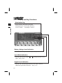
Display and Key Functions
Illumination Key
3
Disp & Func
Turns ON/OFF the display Back-light.
Holding down for one second will show a
screen to adjust: 1.Backlight, 2.Sound
Battery Voltage Level Indication
Indicates the battery level in five steps. (See p.3-4)
Input Mode Indication
Indicates the input key mode ( A or 1 ) during input PT or CD
input. (See p.3-29)
Signal Level indication
Indicates the reflected light intensity in five steps, with two
additional signal status indicators. (See p.3-4)
3-1
Summary
Turns the Power ON and OFF.
PWR
MENU
MODE
REC .
-
-
・○ +
ESC
○
MSR
A
B
1 ○ C
DSP
D
E
2 ○ F
for
detail
p.3-14
Turns the Backlight ON and OFF.
When held down for over one second, it shows a setting
screen for: 1:Backlight, 2:Sound ON/OFF.
p.3-28
Displays MENU items: 1:JOB, 2:COGO, 3:Sett, 4:Data,
5:Comm., 6:Time, 7:Calib. ,8:Note.
Also, a sub-function menu such as DEL/Edit/Add can be
shown by this key in JOB and Data.
p.3-78
Changes the key input mode between alpha-numeric ( A ),
numeric ( 1 ) and Lst/Stk for inputting PT or CD.
Also, the Qcode mode can be activated by this key on the
Basic Measurement Screen (BMS).
p.3-23
Records measurement data.
Holding this key for a second from the BMS, enables to
record data as CP record instead of SS.
In the numeric input mode ( 1 ), enters a decimal point or
minus sign.
In the alpha-numeric input mode ( A ), enters (.), +, -.
p.3-64
Returns to the previous screen.
In the numeric or alpha-numeric input mode, clears the
input data.
Starts measurement based on the measure mode settings
for the MSR key and displays the result.
Holding down this key for a second displays its measure
mode settings (Target, Prism Const., Mode and AVE).
In the numeric input mode ( 1 ), enters 1.
In the alpha-numeric input mode ( A ), enters A, B, C, 1.
When there are two or more display screens, switches
between them.
To change the combination of the display items on
DSP1/4, 2/4 and 3/4 (same as S-O3/8, 4/8 and 5/8),
holding down this key for a second.
In the numeric input mode ( 1 ), enters 2.
In the alpha-numeric input mode ( A ), enters D, E, F, 2.
p.3-17
p.3-20
3-2
3
Disp & Func
Key
TRK
p.3-17
G
H
Initiates a TRK measurement and displays the result.
Holding down this key for a second displays its measure
mode settings (Target, Prism Const., Mode and AVE).
In the numeric input mode ( 1 ), enters 3.
In the alpha-numeric input mode ( A ), enters G, H, I, 3.
J
K
L
Displays the angle menu.
In the numeric input mode ( 1 ), enters 4.
In the alpha-numeric input mode ( A ), enters J, K, L, 4.
p.3-30
Displays the HOT menu.
While in Qcode observation mode, it has to be held down
for one second to activate the HOT menu.
In the numeric input mode ( 1 ), enters 5.
In the alpha-numeric input mode ( A ), enters M, N, O, 5.
p.3-25
Measures differences between remote target points.
In the numeric input mode ( 1 ), enters 6.
In the alpha-numeric input mode ( A ), enters P, Q, R, 6.
p.3-34
Measures the elevation difference between a prism target
point and an arbitrary point on a vertical line extending
from the target point.
In the numeric input mode ( 1 ), enters 7.
In the alpha-numeric input mode ( A ), enters S, T, U, 7.
p.3-36
Sets the station point (known point or arbitrary point).
In the numeric input mode ( 1 ), enters 8.
In the alpha-numeric input mode ( A ), enters V, W, X, 8.
p.3-37
3 ○ I
Disp & Func
3
ANG
4 ○
HOT
M
N
5 ○ O
RDM
6 ○
REM
P
Q
R
S
T
7 ○ U
STN
8 ○
S-O
V
W
X
Y
9 ○ Z
XYZ
*
/
0 ○ =
ENT
○
3-3
p.3-49
Stakeout coordinates or pre-calculated angles/distances.
Holding this key for a second in Stakeout displays a S-O
related settings screen.
In the numeric input mode ( 1 ), enters 9.
In the alpha-numeric input mode ( A ), enters Y, Z, space, 9.
Enables observations without recording ST. HI, HT, Stn p.3-29
coordinate, and BS azimuth can be input.
In the numeric input mode ( 1 ), enters 0.
In the alpha-numeric input mode ( A ), enters *, /, =, 0.
Proceeds to next screen. In the numeric or alpha-numeric
input mode, accepts the input data.
Also, on the BMS, outputs the current measurement data
(Pt/HA/VA/SD) via COM port when “Ext.Comms=Nikon”
is set.
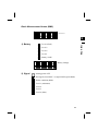
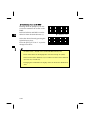
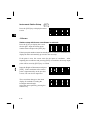
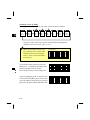
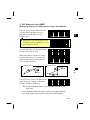
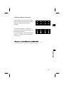
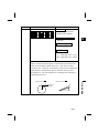
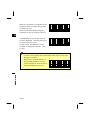
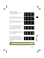
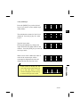
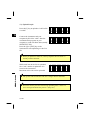
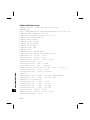
Basic Measurement Screen (BMS)
HA:123°45’50”
VA: 90°15’50”
SDx 1231.008 m
DSP1/4
3
: Level 4 (Full)
Disp & Func
1) Battery
Status bar
: Level 3
: Level 2
: Level 1
: Battery LOW
!Battery Down
: Battery Change
Press ENT key
Change Battery
2) Signal
: Analog power OFF
: No-Signal (slow-blink)or Signal LOW (quick-blink)
: flicker condition (blink)
: Level 1 (minimum)
: Level 2
: Level 3
: Level 4 (Max)
3-4
3-2
Pre-Start
Input Point Name/Number
Input Point Name/Number
3
You can use point numbers or names up to 12 digits in length. When the
system gives you a default PT, basically, the Last recorded PT + 1 is used,
except the case where the last digit is alphabet.
For coordinate records, you cannot use a point name/number that already
exists in the current Job except when you record sideshots or stakeout shots.
(See p.8-2)
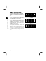
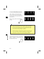
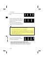
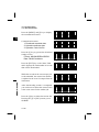
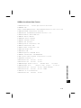
1) Pressing [ENT] without a PT
In COGO, a coordinate input screen will
be displayed if you leave the PT field
blank. This coordinate will be used
temporarily in the calculation and will not
be saved in the database.
Input 1st Point
PT:■
1
HT:
1.5000m
CD:
When you search a point in Stakeout or Data View/Edit without PT, the
system searches the point based on the input CD or other given
conditions. Otherwise, you must enter a PT to record the point.
・The cursor is placed on the first
Input 1st Point
1
character of the string when the input PT:1205
HT:
1.5000m
mode is activated. It is “All Replace” CD:
mode.
・Pressing the right arrow key changes the input mode into
“Overwrite”, leaving the cursor on the first character.
Pressing the left arrow key moves the cursor to the end of the current
input.
3-5
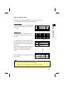
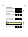
2) Inputting a new PT
PT:55
X:-154.231■
Y:
Z:
1
3
Press the [ENT] key on the last line
(Z:field) to store the point in the current
Job.
3) Inputting a known PT
When a known point name/number is
input, its searched coordinate is displayed
briefly and a beep is sounded before
proceeding to the next step.
Input 1st Point
PT:55■
1
HT:
1.5000m
CD:
[ENT]
PT:55
X:
-52.2310
Y:
2844.3605
Z:
135.3252
beep
Input 1st Point
PT:55
1
HT: 1.5000
m
CD:CP1
3-6
Input Point Name/Number
When you input a new point name/
number, it shows a coordinate input
screen right. You can input a 2D
“NE(EN)”, 3D “NEZ(ENZ)”, or elevation
only “Z” coordinate.
4) When a wildcard (*) is specified
A list of available points are displayed
when you use an asterisk to input PT or
CD.
Input Point Name/Number
3
Use the up/down arrow keys and [ENT] to
select the point you want to use.
If more than four points match the input
conditions, there will be a ↓ sign in the
lower right corner. You can also use the
Right/Left arrow key to
page-up/page-down the list. (See p.3-12)
When you select a point from the list, its
coordinate is displayed briefly and a beep
is sounded before proceeding to the next
step.
3-7
Input 1st Point
PT:
A
HT:
1.5000m
CD:FENCE*■
[ENT]
MP,12,FENCE3
UP,23,FENCE6
>MP,39,FENCE51
[ENT]
PT:39
X:
-52.2310
Y:
2844.3600
Z:
135.3250
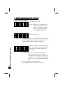
How to input a Code
Basically, CD: field is defaulted to the code previously used.
You can change it on the recording point screen.
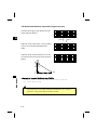
1) Manual Input
3
PT:10006
HT:
1.5000m
CD:CURB87■
1
2) Stack Input
Press the [Stk] key to display a list of
Code stack. The stack may contain up to
20 codes.
PT:10006
HT:
1.5000m
CD:CURB
Lst O/S Qcd Stk
[Stk]
To select the previously used code, press
the [Stk], then use the down arrow key to
move the cursor downwards through the
stack list.
The up arrow key moves up through the
stack. Press the [ESC] key to get out of
the Stack List without choosing any
codes.
CURB
>TRAIL
HEDGE
BUILDING
↓
PT:10006
Press the [ENT] key to input the code into HT:
1.5000m
CD:BUILDING
the CD field.
Lst O/S Qcd Stk
・Each code can be input up to 12 characters.
・When you re-boot the program, Stack area will be cleared.
3-8
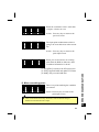
How to Input a Code
Press the [Mode] key to change the input
mode into alpha-numeric (A) or numeric
(1) mode.
3
Press the [Lst] key to display a feature
code List. It shows the first four codes
from the first layer.
To edit the Code List, you can go into
MENU/4:Data/3:Code List.
(See p.3-109)
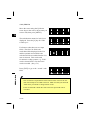
How to Input a Code
3) Code List
There is a “→” at the end of each Layer
STRUCTURE
name. “Layer” has more Codes
>SURFACE→
SURVEY→
underneath. For example, when you press
VEGETATION
the [ENT] key on “SURFACE→”, it
shows another layer under the
[ENT]
“SURFACE”
When a feature code is selected, it is
added to the CD: field. If a code already
exists and the cursor is on its first
character, it will be replaced by the new
code.
PT:10053-A10
HT:
1.6050m
CD:CURB
Lst O/S Qcd Stk
[Lst]
>CMP
MB→
RCP
SPR
All items in the List are shown in alphabetical order. The “first
character search” is also available to find a desired code quickly.
You can just input the first character of the feature code directly by
using ten-key. While the List is shown, the ten-key is actually set to
alpha-numeric input mode. (See next page)
3-9
↓
================== Advanced Functionalities ==================
The First character Search in List
When you hit the [7] key once, it shows
“S” in input mode field to indicate the
selected character. It changes to “T”
when you press it again within a certain
duration.
When the input is fixed, the cursor
moves to the feature code beginning
with the character you input.
If the exact item doesn’t exist, the
cursor moves to the next available
choice, i.e., next one in alphabetical
order.
>BACK
BUILDING
CURB
DUOMO
S
↓
>BACK
BUILDING
CURB
DUOMO
↓
>TREE→
TUNNEL
UTIL→
YOKOHAMA→
↓
T
===========================================================
4) Qcode
This is a quick and frequent function to shoot and record many points with
feature codes in the field. You can use up to 10 Quick-codes at a time.
Before activating Qcode mode or while you are in it, you can newly assign a
code to any numeric key or edit the code currently assigned to a key. (See
p.3-27, 3-65)
3-10
3
How to Input a Code
For instance, when you want to see the
feature code begins with “T”, you can
just hit [7] key twice, while it shows a
List.
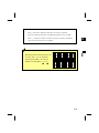
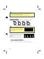
How to Input the Feet-Inches on the Instruments
How to Input the Feet-Inches on the Instruments
3
When either US Survey Feet (US-Ft) or International Feet (I-Ft) is selected
as the distance unit, there is an option for values to be input and displayed in
decimal feet, or in feet and inches (See p.3-93). All distances, HI’s, HT’s
and coordinate values will be entered and displayed in feet and inches.
The input screen allows you to enter “feet and inches” element by element
separated by periods.
Feet → [.] → Inch → [.] → Numerator → [.] → Denominator → [ENT]
(0~11)
(0~15)
(1~99)
If the denominator is 16, you don’t have to
key in 16. When you press the [ENT] after
inputting the numerator, the system
understands that the denominator is 16.
Denominator “16 (for 16th inches)” is not
displayed on the screen. 2’08”5/ indicates
2 feet, 8 and 5/16ths inches. Refer to the
following examples:
• 65’ 5 3/8” is entered 65.5.3.8
• 65’ is entered 65
• 65’ 5” is entered 65.5
• 65’ 5 3/8” can be entered 65.5.6
• 5 3/8” is entered 0.5.3.8 or 0.5.6
PT:1462
HT:2.0.5
CD:FENCE
[ ]
1
[ENT]/ [ ]
PT:1462
HT:
2’08” 5/
CD:FENCE
Input value (numerator/denominator portion) is automatically converted to
the closest value from the following.
0, 1/8, 1/4, 3/8, 1/2, 5/8, 3/4, 7/8, 1/16, 3/16, 5/16, 7/16, 9/16,
11/16, 13/16, 15/16
(The denominator 16 is not shown on the screen.)
3-11
A
↓
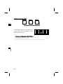
List Displays
“>” on the first line shows the current
cursor place.
“↓” on the lower right corner means that
there are more pages after this page.
When you see this sign, you can use the
Right/Left arrow key to page up or down
the list.
>UP,502
UP,503
UP,504,CE
UP,505
↓
Press the Up/Down arrow key moves cursor one by one. To pick up one
record from the list, press the [ENT] key after you move the cursor to the
desired record.
In some cases, the [Mode] key is also available on this “list” screen to
activate a sub-function menu.
3-12
3
List displays
You will see the same type of “list” display in View/Edit data
(MENU/4:Data), Code List function, Qcode Edit (HOT/5:Qedit), and Job
manager (MENU/1:JOB).
There are some common rules to operate this “list”.
About Jobs
When you record data on the instrument, you must create or open a Job.
Up to 8100 records can be stored to one Job database. You can have a
maximum of eight Jobs at one time. (See p.3-78 for detail)
About jobs
3
Please check the settings first when you use the
instrument for the first time.
Settings Æ Create Job
1) Enter [MENU] and [3:Sett].
2) Check the settings at least [1:Angle], [2:Dist], [3:Coord.], and [5:Unit].
There are some job settings in them. You cannot change any of the job
settings after creating a job.
3) After checking those settings, press [ESC] to return to MENU screen.
4) Press [1:Job], [MENU], and [1:Create].
You can confirm the current job setting via [2:Set] key in “Create JOB?”
screen.
Control Job
1) Create a job in the office and store some coordinate data that may be used
by several field works.
2) Press [MENU] and [1:Job]. Move the cursor onto the job you want to use
as a common file (control job).
3) Press [MENU] again and choose [3:Control].
The system will search the coordinate points in the Control
Job when the input point cannot be found in the current Job.
If the point is found in the Control Job, it will be copied into
the current Job. (See p.3-82)
3-13
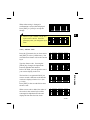
3-3
Getting Started
PWR
Turn On the Instrument
TILT TELESCOPE
>Temp
20°C
Press 1013hPa
2000-07-17 11:35
The current Temperature and Pressure are
displayed.
The displayed value can be modified on
TILT TELESCOPE
>Temp
20°C
1
the spot after pressing the [ENT] key.
Press 1013hPa
Use the up/down arrow keys to select the 2000-07-17 11:35
desired item.
Tilt the telescope past the horizontal
position in the face-left position.
It will automatically resume the last job
and return to the screen where the
instrument was previously powered off.
If you choose the [Rst] option when turning off the instrument, it
restarts the software from the Basic Measurement Screen
(BMS) without having any JOB opened.
3-14
3
PWR
Press the [PWR] key to turn on the
instrument. The start-up screen shown
right appears.
Rotating the alidade before tilting the HA INITIALIZED
>Temp
20°C
telescope initializes the HA.
Press 1013hPa
2000-07-17 11:35
3
PWR
・When the telescope is tilted before rotating the instrument, the
horizontal angle is not initialized. Instead, it simply recalls the last
HA reading before Power OFF.
・The previous orientation can only be recalled if the HA was
initialized before the original HA was set. When you prefer to
recall orientation using this method, it is recommended that you
get accustomed to rotating the alidade whenever you turn ON the
instrument.
3-15
Press [PWR] and [ENT] to turn off the
instrument.
ENT
○
Press ENT →OFF
Rst
Save
[2:Rst]=re-boots the program and starts over.
[4:Save]=puts the instrument into sleep mode.
[ESC]=cancels the power-off process and returns to the previous
screen.
“Sleep mode” is automatically activated
based on the Power Save setting (see
p.3-91) or when the [2:Save] is selected
on the above screen.
In this mode, LCD backlight is to be
turned off.
Sleeping..
Any key input, receiving a remote control
command or rotating the instrument will
wake up the instrument.
3-16
3
PWR
PWR
Turn Off the Instrument
Measuring Distances
MSR
A
B
1 ○ C
TRK
G
H
3 ○ I
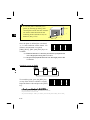
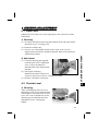
1) Sighting a prism reflector
3
WARNING
Never view the sun through the
telescope.
Doing so may cause loss of eyesight.
MSR/TRK
Sighting a single prism
Sight the telescope crosshairs on the center of
the prism reflector. When reflected light is
detected, the signal level is indicated.
Sighting a tiltable single prism
For assembling the prism reflector, refer to p.2-11.
3-17
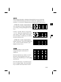
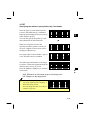
2) Measuring distances
HA: 90°15’50”
VA:123°45’50”
SDx 1241.008 m
DSP1/4
When the Average count is set to 0, measurements are taken continuously
until [MSR]/[TRK] or [ESC] is pressed. Each time a measurement is taken,
the distance is updated.
For the Average count is set to 1–99, the averaged distance is displayed after
the last shot. The header “SD:” changes to “SDx” for this value.
If the signal level is insufficient for measurement, the signal icon will blink.
(See page 3-4)
・To change the Height of Target,
Temperature and Pressure, or
settings for measurement, press the
[HOT] key from any observation
screen. (See page 3-25)
5:Qedit
1 :HT
2:T-P
6:Qmode
3:Meas.
4:Level
・T-P correction, Sea level correction, C&R adjustment and Map
projection are included in Job settings. They can be defined when
creating a job. (See page 3-79)
・When the [MENU] key is pressed on the BMS or any other observation
screens, it stops the measurement and displays the MENU screen.
3-18
3
MSR/TRK
Press the [MSR] or [TRK] key on the
BMS or any other observation screens to
take a measurement.
3) Measurement mode settings
Holding down the [MSR] or [TRK] key
for one second shows the measurement
settings for each key.
MSR/TRK
3
>Target
Const
Mode
AVE
:Prism
: 30mm
:Prec
:2
Move the cursor by the up/down arrow
keys and use the right/left arrow keys to
change the setting.
Target = Prism/Sheet
Prism constant (Const) = –999~999mm
Mode = Prec/Normal
AVE
= 0 (Continuous) ~ 99
“ --- ”(for Prism) or “ ) ) )”(for Sheet) is displayed during the
measurement depending on the Target setting.
In order to apply better cyclic error adjustment in distance measurement,
the 'Target' setting is introduced. It efficiently eliminates multi-path
reflection.
3-19
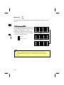
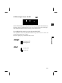
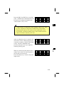
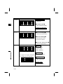
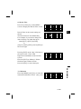
Switching between Screens
DSP
D
E
2 ○ F
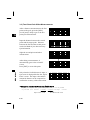
1) Changing display
1/4 screen
Press the [DSP] key to change the
contents of the screen on the Basic
Measurement Screen (BMS).
HA: 90°15’50”
VA:123°45’50”
SD:
284.563 m
DSP1/4
Change of the screen can be done before,
during or after a measurement.
On the BMS, pressing the [REC] key
from any of these screens will store a SS
record.
Depending on the “Store data” setting, it
will record RAW data (HA,VA,SD),
coordinate data (X,Y,Z) or Both. (See
p.3-93)
2/4 screen
HA: 90°15’50”
VD:
15.635 m
HD:
266.347 m
DSP2/4
DSP
Upon each press of the [DSP] key, the
screen scrolls among DSP1/4 to 4/4.
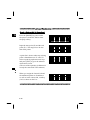
3/4 screen
HL:269°44’10”
V%:
15.28
%
HD:
266.347 m
DSP3/4
4/4 screen
X:
-4435.256
Y:
288.953
Z:
15.325
DSP4/4
When the Secondary Unit is set to
any distance unit, it shows HD/ VD/
SD in the specified unit as the fifth
screen. (See p.3-93 for Secondary
Unit setting)
3
<for “Ft-inch”>
H:
700’07”1/4
V:
-6’02” 0
S:
999’11”15/
DSP5/5
Screens can be changed using the DSP key in the BMS, RDM,
Stakeout, and Data View functions.
3-20
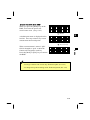
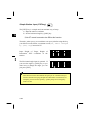
2) Customizing items on the BMS
HA: 90°15’50”
VA:123°45’50”
SD:
284.563 m
DSP1/4
Select the desired item by pressing the
right/left arrow keys.
Press the [ENT] on “Line 3” to put the
changes into effect.
Select Items
>Line1:HA
Line2:VA
Line3:SD
DSP
3
Holding down the [DSP] key for one
second to customize the screen on the
BMS.
DSP1/4, DSP2/4, and DSP3/4 can be
edited to show the desired items. (*)
[DSP] for 1 sec.
・Available items : HA/HL/VA/V%/SD/VD/HD/N/E/Z/(none)
・None of the items can be displayed in two lines except for (none) .
・The items showed in DSP1/4, 2/4, 3/4 and 4/4 are also used in Stakeout
(S-O3/8, 4/8, 5/8 and 6/8).
・Changing the combination of display items can be done in Stakeout as
well.
3-21
= Header characters =
・ The ":" character indicates that Tilt correction is applied.
・ The "#" character indicates that Tilt adjustment is set to OFF.
・ The "_" character under the Tilt correction character indicates
3
that Sea Level Correction is applied.
following the "HD", "N" and "E"
headers are changed to ":" or "#".
DSP
HA: 90°15’50”
VD:
15.635 m
When the Sea Level Correction is set
HD:
266.347 m
to "ON", the ":" or "#" character
DSP2/4
X#
-4435.256
Y#
288.953
Z#
15.325
DSP4/5
3-22
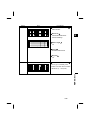
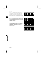
Mode key
MODE
The [Mode] key changes the the keyboard mode depending on the current
screen.
3
1) While Inputting PT/CD
MODE
Pressing the [Mode] key while the cursor
is in the PT field changes the input mode
between Alpha-numeric (A) and
Numeric (1). When the cursor is in the
CD field, three input modes are available,
i.e., (A), (1), and (Lst, Stk).
:Numeric
:Alpha-numeric
Input Point
PT:1
CD:FENCE2■
[Mode]
Input Point
PT:1
CD:FENCE2■
[Mode]
Input Point
PT:1
CD:FENCE2
Lst O/S Qcd Stk
Offset recording (O/S) and Qcode assigning function (Qcd) are
available in the recording screen of the BMS. (See p.3-65 through
3-66)
3-23
A
1
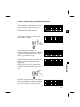
2) Quick Code Mode (from BMS)
When you press the [Mode] key on the
BMS, it activates the Quick code
measurement mode. (See p.3-65)
HA:316°50’40”
VA: 91°25’35”
SD:
150.687 m
DSP1/4
[Mode]
A default point name is displayed on the
last line. Press any numeric key to start
measurement and record points.
HA:316°50’40”
VA: 91°25’35”
SD:
150.687 m
QPt=10053-A10
3
HA:316°50’40”
VA: 91°25’35”
SD:
150.687 m
Qcd=CURB
・To assign a feature code to each key Æ HOT/5:Qedit (See 3-26)
・To change the Qcode recording mode Æ HOT/6:Qmode (See 3-27)
3-24
MODE
Any [1] to [0]
When a measurement is started, “QPt”
field is changed to “Qcd” to show the
feature code assigned to each key.
Press the [Mode] or [ESC] key to return to
the BMS.
HOT key
3
HOT
M
N
5 ○ O
The [HOT] key is available from any
observation screen. It shows the screen
on the right.
Press the [ESC] key to return to the
previous screen.
1:HT
5:Qedit
2:T-P
6:Qmode
3:Meas.
4:Level
1) Height of Target
You can define the height of target by
pressing the [HOT] and [1] keys.
HOT
2) Temperature & Pressure
Input HT
HT: 1.3560
m 1
Input T-P
Set the current temperature and pressure
1
Temp: 22 °C
using this command. Press the [HOT] and Press:1013 hPa
(ppm=0.4)
[2] keys from the BMS or other
observation screens and type the ambient
temperature and pressure.
3) MSR/TRK Key Settings
Press the [HOT] and [3] keys to show the Measure mode
1:MSR
Key
1
[MSR] or [TRK] key settings.
2:TRK Key
(Same screen displayed by holding down
[MSR]/[TRK] for one second; See p.3-19)
[1]/ [2]
Move the cursor by the up/down arrow
keys and use the right/left arrow keys to
change the setting.
Target = Prism/Sheet
Prism constant (Const) = –999~999mm
Mode = Prec/Normal
AVE = 0(Continuous) ~ 99
3-25
>Target
Const
Mode
AVE
:Prism
: 30 mm
:Prec
:1
4) Level
The leveling indication is displayed automatically on any measuring
screen if the instrument goes out of level while the compensators are
turned on. It can also be displayed by pressing the [HOT] and [4] keys.
3
<DTM-350 = 2axis compensation>
You can turn the leveling compensators
on or off by pressing the Right/Left arrow
keys.
:-0’05”
: 0’03”
It shows “OVER” when it is larger than
±3’30”. When the compensation is set to
off, it shows “OFF” on the screen right.
Press the [ESC] or [ENT] key to return to
the observation screen.
HOT
:-0’36”
: OVER
<DTM-330 = 1axis compensation>
DTM-330 has the vertical axis adjustment
only. It can be turned ON/OFF by the
Right/Left arrow keys.
-LEVELING-
-1’36”
5) Qedit
The list of feature codes currently
assigned in Quick code mode are
displayed.
>1
2
3
4
Directly input the key number or select
the one by the Up/Down arrow keys.
Then, press the [ENT] key to start typing
characters in.
>7 ■
8
9
0
HEDGE
FENCE
BUSH
MANHOLE
↓
A
Press the [ENT] key or Up/Down arrow
key to complete input. Press the [ESC]
key to return to the observation screen.
3-26
6) Qmode
This function defines the setting for
Qcode mode.
3
Qcode Modes
>Confirm
:Yes
Meas mode:MSR
Confirm: “Yes” = displays the point input screen to confirm PT/HT/CD
before recording each measurement.
“No” = skips the point input screen and directly stores the
point after a measurement.
HOT
Meas mode (Measurement mode): Defines whether the measurement
settings for MSR or TRK are used when a key is pressed in
Qcode mode. You can use the setting defined for [MSR] or
[TRK] key. (See p.3-19)
When the average count is set to “0” (Continuous) for the selected
MSR/TRK mode, only one measurement is taken in Qcode mode.
3-27
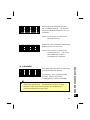
LCD Backlight Sound On/Off
1.
2.
The LCD backlight can be turned ON/OFF by pressing the illumination key.
Holding down the illumination key for one second activates the Backlight
and Sound ON/OFF switches from any observation screen.
3
Light/Sound
Use the Right/Left arrow keys to turn the switch ON/OFF.
The Up/Down arrow keys and the numeric keys can be used to move the
cursor between the item 1 and 2.
Press the [ESC] key to terminate this screen.
1) Backlight
: Backlight OFF
: Backlight ON
2) Sound
: Sound OFF
: Sound ON
3-28
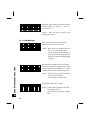
Simple Station input (XYZ-key)
3
XYZ
*
/
0 ○=
The [XYZ] key is a simple and conventional way of setup.
1) Input the station coordinate
2) Set the horizontal angle by [ANG] key
※No ST record is stored to the DB in this function.
XYZ
Therefore, when you try to record data to an open job after using this key,
your SS/CP records follow a comment record (CO, STN is changed
by [XYZ] key) instead of ST.
Input Height of Target, Height of
Instrument, XYZ coordinate of the
Station.
HT: 1.356
m
HI:
1.646 m 1
X:
3864.990
Y:
-1872.507
The Horizontal angle input is optional. If
you reset the angle by [ANG] key or you
don’t have to change the angle, you can
just press [ENT].
X:
Y:
Z:
HA:
3864.990
-1872.507
42.185
This function can be used without an open job. It is useful when you
need to continue surveying despite the “Data Full” environment, for
example, you can use this [XYZ] + [ANG] setup as an emergency
means on site.
3-29
1
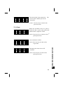
3-4
Applications
HA Reset and Measurements
ANG
J
K
4 ○ L
Perform face-left and face-right measurements to obtain maximum
accuracy for measuring angles. (Refer to p.2-15) By doing so,
mechanical constant error (except in some special cases such as the
vertical axis error) can be effectively cancelled out.
3
Press the [ANG] key to display the angle
HA:120°15’50”
4:F1/F2
menu screen. Select the desired item 1:0-Set
1
2:Input
5:Rept.
pressing the numeric key.
3:Hold
・ F1/F2 is not supported in DTM-330.
ANG
1)0-Set
Setting the horizontal angle to 0
Press the [1] key to reset the horizontal
angle to 0. The display returns to the
basic measurement screen after resetting
the horizontal angle.
2)Input
Inputting the horizontal angle
Press the [2] key, and the numeric input
screen is displayed.
Input the horizontal angle using numeric
keys and press the [ENT] key.
HA:123.45■
1
ANG
Ex.) To enter 123º45’50”, key input should be 123.4550.
・The displayed value is rounded to the minimum increment of angle.
3-30
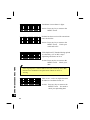
3)Hold
Horizontal Angle Hold
Press the [3] key to hold the horizontal
angle to the current value.
3
HA: 65°10’00”
- HA Hold -
Abrt
Set
Press the [4:Set] or [ENT] key to set the
horizontal angle as it is displayed. After
setting the angle, it returns to the basic
measurement screen.
Press the [1:Abrt] or [ESC] key to cancel
holding and setting the horizontal angle.
4)F1/F2 (Not included in DTM-330)
ANG
Face1/Face2 measurement
Without taking a distance measurement,
you can take F1/F2 data by pressing
[ANG]Æ[4:F1/F2].
HA: 57°09’18”
1:0-Set 4:F1/F2
4
2:Input 5:Rept.
3:Hold
[4]/[ENT]
If you take a measurement to the target,
you can initiate F1/F2 measurement by
just flipping the telescope to different
side.
To store the F1/F2 records and its
average data, the observation to the
Backsight has to be F1/F2.
3-31
Turn to F2
(ESC for Abort)
!STN Setup has
to be F1/F2
Press any key
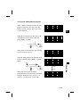
5)Rept.
Recording a foresight point after repeat angle measurement
Press the [4] key to display “0” as a
HRΣ
0°00’00”
- HR Hold -
horizontal angle and activate repeat angle
measurement mode.
ANG N= 0
3
Press the [ENT] key to accumulate the
HRΣ 250°00’50”
horizontal angle, and press the [ENT] key VA: 91°24’50”
again to hold the current horizontal angle.
ANG N=05
To cancel repeat angle measurement
mode, press the [ESC] key.
Press the [REC] key to average the
horizontal angle. The horizontal angle
display is fixed until the process is
finished or cancelled.
HRx
50°00’10”
HA: 300°01’00”
Press MSRorTRK
ANG N=05
ANG
HRx = HRΣ ÷ N
HA = BSAz + HRx (normalized)
By pressing the [MSR] or [TRK] key, the
VA and SDx are displayed after the
measurement to the foresight point.
HRx will not be updated even if the
instrument is moved.
HA:300°01’00”
VA: 91°24’50”
SDx
33.860 m
ANG
Press the [REC] or [ENT] key again, and
the default point number and code for the
foresight point are displayed. Press the
[ENT] key to record.
PT:18
HT:
1.600 m
CD:EDGE1
Lst
Stk
3-32
・In this mode, the display “:” following “HA” is replaced with “Σ”
and the number of repeat angles is displayed after “N=”.
3
・Horizontal angles can be measured up to 1999º59’59”.
・This function will store both RAW and XYZ data (as CP record)
after the foresight point is measured regardless of the “Store DB”
setting.
・While in the repeat angle measurement mode, distance
measurements cannot be taken or recorded.
ANG
・Once the HRx is calculated after some repetition shots, the
horizontal angle display will not change until the process is
finished or aborted.
3-33
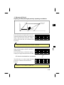
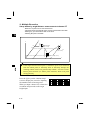
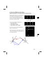
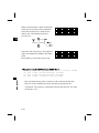
RDM
Remote Distance Measurement
P
Q
6 ○ R
Measures the horizontal distance, vertical distance and slope distance
between two points.
3
2nd sighting point
rSD
rVD
1st sighting
point
rHD
Horizontal angle 0 direction
2nd sighting point
rHA
rSD :Slope distance between two points
rHD :Horizontal distance between two points
1st sighting
point
rVD : Vertical distance between two points
rV% :Percentage of grade (rVD/rHD) x 100%
rGD :Vertical grade (rHD/rVD) :1
Station point
Press the [RDM] key to display the menu
screen shown right. Select a desired item
pressing the numeric key.
RDM
rHA :Azimuth from first point to second point
1 :Continuous
2:Radial
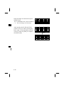
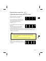
RDM
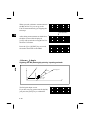
Difference between "1: Cont." and "2: Radial"
P3
P3
P4
P4
P2
P2
P1
P1
1: Cont.
(The preceding two points are
subject to calculate.)
2: Radial
(Calculations are made with
reference to the first point.)
3-34
1: Cont
Measuring between the current point and the immediately
preceding point
2: Radial
3
Measuring between the current point and the first point
measured
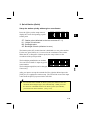
The screen shown right appears by
rSD:
selecting 1 or 2 in the RDM menu. Sight rVD:
the 1st point and press the [MSR] or
rHD:
RDM1/2
[TRK] key.
RDM
The distance from the station point to the
1st point is displayed.
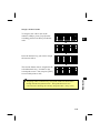
Sight the 2nd point and press the [MSR]
or [TRK] key. The distances between the
1st and 2nd point are displayed.
m
m
m
rSD:
15.6735m
rVD:
2.5810m
rHD:
15.4271m
RDM1/2
rSD:
55.3651m
rVD:
5.4212m
rHD:
50.2687m
RDM1/2
rSD : Slope distance between two points.
rVD : Vertical distance between two points
rHD : Horizontal distance between two points
Press the [DSP] key to change data
displays.
rHA:350°26’50”
rV%:
10.74%
rGD:
15.160:1
RDM2/2
rHA : Azimuth from 1st point to 2nd point
rV% : Percentage of grade (rVD/rHD) x 100%
rGD : Vertical grade (rHD/rVD) : 1
3-35
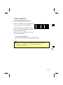
Remote Elevation Measurement
REM
S
T
7 ○ U
A prism is required only at
Arbitrary point
the sighting (target) point
Z
as a reference point.
3
Θ
Vh
Sighting point
Station point
VD
HT
HD
Vh = HD・tan(90°-Θ) – VD + HT
Press the [REM] key to display the screen
shown right. HT can be input from here.
HT: 1.2500
Vh:
m
m1
Sight the target point and press the [MSR]
or [TRK] key.
HT:
1.2500m
Vh:
m
Press MSRorTRK
REM
Loosen the vertical clamp, and turn the
HT:
1.2500m
telescope to aim at an arbitrary point.
Vh:
-1.2364m
HT Recording
The elevation difference between the
target ground point and the arbitrary point REM
will be displayed.
You can update the Height of target by REM measurement.
Sight the bottom of the prism pole and press the [REC] key after
shooting to the prism.
3-36
REM
REM
Instrument Station Setup
STN
V
W
8 ○ X
Press the [STN] key to display the menu
screen.
3
Station Setup
1
1:Known 4:RBM
2:Resec 5:BSChk
3:Quick
1:Known
Station setup with known coordinates or azimuth
Press the [1] key to display the screen
ST:■
shown right. Input the station point
HI:
0.000 F 1
CD:
number/name and press the [ENT] key.
If the input point number/name has already been recorded, its coordinates are
displayed and it automatically proceeds to the next step.
STN
If the point is new, the screen waits for the input of coordinate. After
inputting the coordinates and pressing [ENT] on each line, the newly input
point will be stored by [ENT] key on Z field.
Input the Height of Instrument and press
[ENT]. If the coordinate of the station
point is input manually on the previous
screen, CD: can also be input here.
The screen then changes to the menu
display for methods of setting the
backsight azimuth angle.
Select the menu option by pressing the
numeric key.
3-37
ST:1062
HI: 4.000
CD:POT
Backsight
1
1:Coord.
2:Angle
F 1
1: Known→1:Coord
Sighting the BS (backsight) point by inputting coordinates
X
Z
Xb
Instrument height
X0
Backsight point
(Xb, Yb, Zb)
Y0
3
Station point
(Xi, Yi, Zi)
Y
Yb
Press the [1] key to display the screen for
inputting the BS point name and Height of
target. Type the point name first. When
the Pt exists in the Job, its coordinates will
be shown.
Input BS Point
PT:■
HT:
1.6280m
CD:
1
Sight the Backsight on FACE1 and take a
measurement.
Press the [ENT] key to finish the station
setup by an angle measurement to the BS.
Sight BS
AZ:123°45’50”
Press MSRorENT
STN1/2
F2
AZ: Azimuth calculated from coordinates
The [4:F2] key is to take an angle shot and
proceeds to another measurement on
FACE2.
[4]
Turn to F2
(ESC for Abort)
[F2] key is not available in DTM-330.
3-38
STN
Code can be input only when a new PT: is entered.
When you take a distance measurement to Sight BS on F2
AZ:123°45’50”
the BS on FACE1, you can go to the
HD:
87.9577m
FACE2 measurement by just flipping the STN1/2
telescope.
[ENT]/[REC]
3
After taking measurements on both faces,
the delta screen will be displayed.
[3:CP] will records the averaged HA/VA/
SD from F1/F2 data.
Press the [3] or [4]/[ENT] key to record
the station and return to the BMS.
dHA:
dVA:
dSD:
Abrt
0°00’21”
0°00’43”
0.0063m
CP
OK
- REC STN -
Job:PROJ582
1:Known→2:Angle
Sighting the BS (backsight) point by inputting azimuth
STN
X
Z
Backsight point
X0
Instrument height
Azimuth
Station point
(Xi, Yi, Zi)
Y0
The BS point input screen.
If you don’t use any point name for the BS,
just press the [ENT] key at a blank PT.
3-39
Y
Input BS Point
PT:■
HT:
1.6280m
CD:
1
The screen for inputting the azimuth to the Input BS Angle
BS point is displayed. Just pressing the
1
AZ:■
[ENT] key inputs 0º00’00”.
3
Ex.) To enter 123º45’50”, key input should be 123.4550.
Sight the BS point and press the [ENT]
key. It records the station and returns to
the BMS.
F1/F2 observations to the BS is also
available by [4:F2] key or just flipping
the telescope to Face2 after taking a
distance measurement on Face1.
Sight BS
AZ:
0°00’00”
Press MSRorENT
STN1/2
F2
The [DSP] key changes the indication
between STN1/2 and STN2/2.
On either screen, press the [ENT] key to
record the Station.
Sight BS
VA:
0°00’00”
SDx
217.4916m
STN2/2
F2
3-40
STN
AZ: Input azimuth to the BS
2: Multiple Resection
Setup station by angle/distance measurements to known PT
- Maximum 10 points can be used in Resection.
- Calculation starts automatically when enough measurements are taken.
- Deleting any poor observation data can be done.
- Selecting BS point is available.
3
X
Known point 1
(X1, Y1, Z1)
Instrument height
X0
Height 2
X1
X2
Height 1
Z
Known point 2
(X2, Y2, Z2)
Station point(Xi, Yi, Zi)
Y
Y1
Y0
Y2
STN
If the angle between known point 1 and known point 2 (as measured
from the station point) is extremely acute or extremely oblique, the
resulting solution will be less geometrically reliable. It is best to select
known point locations (or station point locations) which will yield
strong geometry.
Press the [2] key on the “Station Setup”
screen to display the screen for inputting
the number/name of known point 1.
When you input a known PT, it shows the
coordinate and proceeds to the target
height input.
3-41
Input 1st Point
1
PT:■
HT:
1.5000m
CD:
Input the target height and press the
[ENT] key. When the coordinate is input
manually on the previous screen, CD: can
be input on the screen. (Lst/Stk input are
not available on this screen.)
Sight known point 1 and press the [MSR],
[TRK], [4:F2] or [ENT] key. The [4:F2]
and [ENT] take an angle measurement.
Input 1st Point
1
PT:55
HT: 1.5000
m
CD:CP1
Sight PT1 on F1
HA: 150°30′27″
Press MSRorENT
STN1/2
F2
3
[MSR]
Sight PT1 on F1
HA: 150°30′27″
HD:
106.4289m
STN1/2
F2
Input the second PT and the height of
target and take a measurement to the
second point.
Input 2nd Point
PT:■
1
HT:
1.5000m
CD:
STN
By pressing [4] or just flipping the
telescope to Face2, you can take F1/F2
measurements.
Press the [ENT] key to proceed to the next
point input.
[F2] key is not available in DTM-330.
3-42
3
Once the data enough to calculate the
Station coordinates are obtained, its
standard deviation screen will be
displayed.
Press [ESC] to return to the last
measurement screen.
Press [1] to add more direction to enhance
the accuracy of your resection.
When you are satisfied with the result,
press [4] or [ENT] to record the station
through ST input & Select BS screen.
σN:
0.0193
σE:
0.0084
σZ:
0.0270
Add DSP View REC
[2:DSP]
[2:DSP]
N:
280.4193
E:
-7.0814
Z:
16.0270
Add DSP View REC
For [3:View] functionality, please turn to
the next page for details.
・In 2-Pt Resection, one point is distance measured while the other is
angle measured, the sigma values will not be available.
STN
・When the known PT has a Z-coordinate, the Stn-Z will be given for
your reference even without a distance measurement. If you take a
distance measurement to any point, the Stn-Z will be calculated by
that measurement, not from any angle measurements.
3-43
================== Advanced Functionalities ==================
View&Delete each data in Resection
By pressing [3:View] key on the
calculated STN data screen, you can
check your observation to each direction.
>45,CP1
37A,CP2
111,POLE/CT
[ESC]
Place the cursor on a bad data or show its
detail data, you can press [MENU] and [1]
to delete it.
[2:Add] will provide you another PT input
screen to continue the resection
observations.
When you select an unnecessary point and
choose [MENU]Æ[1:DEL], a
confirmation screen will be shown.
After deleting it, recalculation will be
started the STN coordinate with
remaining data.
[ENT]
PT:45
dHA:
0°00′25″
dVD:
0.0123m
dHD:
0.0030m
1 DEL
2 Add
STN
dHA : distributed errors in HA to each
direction
dVD : errors in VD between measured
distance and calculated data
based on its known coordinates
dHD : errors in HD between measured
distance and calculated data
based on its known coordinates
3
[ESC]
[ENT]/[1]
Delete Shot?
PT:45
No
Yes
===========================================================
3-44
Input the height of instrument and press
the [ENT] key.
“ST” is defaulted to the “Last recorded PT
+ 1”. You can change it if necessary.
ST:250
HI: 0.0000
CD:
After inputting the ST, HI and CD for
station record, you will be selecting the
Back- sight. Choose the BS by up/down
arrow key and press [ENT] to complete
the Station setup.
Select BS PT
>55,CP1
23,POLE
18E,
m
1
3
[ENT]
- REC STN -
STN
Job:PROJ5963
3-45
↓
3: Quick Station (Quick)
Setup the station quickly without given coordinates
Press the [4] key on the setup menu to
display the screen for inputting a quick
station point.
ST:1507
HI: 0.0000
m
BS:
AZ:
0.0000g
1
3
ST : Station point (defaulted to the Last recorded PT +1)
H I : Height of Instrument
BS : Backsight point
AZ : Backsight azimuth (defaulted to zero)
The Station point (ST) in this function is defaulted to a new point number.
For the new point, MP (0, 0, 0) is stored as the coordinate of the station.
When the ST is changed to a known point, the setup is done on the
coordinate of the point specified.
ST:1507
HI:
1.8150m
BS:■
AZ:
0.0000g
1
STN
The backsight point(BS) has no default.
You can leave it blank or input any point
name/number.
The backsight angle(HA) can be changed,
if necessary.
After you input or accept the azimuth for HA, sight the BS and press the
[ENT] key to complete the station setup. The HA will be reset to the input
value when the [ENT] is pressed at the AZ field.
Even if both of ST and BS are known points, this function does not
calculate the backsight angle (AZ) automatically. When you want
the AZ to be calculated between two known points (ST and BS),
you need to use STN/1:Known. (See p.3-37)
3-46
4: Remote Benchmark (RBM)
Determine the station elevation
3
Input the BM point and press the [ENT]
key. When the point is found in the
current or specified Control Job, it is
displayed.
Input BM Point
PT:■
1
HT:
2.1400m
CD:
After inputting the Height of Target, sight
the BM and press the [MSR] or [TRK]
key.
Sight BM
Press MSRorTRK
STN
[MSR]
You can take F1/F2 measurements by
pressing the [4] key or just flipping the
telescope to Face2.
Sight BM
VD:
1.1184m
HD:
86.7521m
STN
F2
[ENT]
STN
[F2] key is not available in DTM-330.
The coordinate of the station point is
displayed with the updated Z-coordinate.
The HI can be changed on this screen.
X:
-154.231
Y:
2345.362
Z:
135.325
HI: 1.8140
m
Z: The elevation of the station, calculated from the BM
point measurement.
・When the HI is changed, the Z-coordinate will be updated before
recording the station.
・If you have not already completed a station setup, the Remote
Benchmark function is not available. An error screen will be
shown. (See p.8-1, 3rd screen)
3-47
1
5: BSCheck (BSChk)
Check the Backsight direction
Press the [5:BSChk] on the station setup
menu to enter the BS check function.
HA:103°50’34”0
BS:103°50’30”5
Abrt
Sight the BS and press the [ENT] or [4]
key to reset the horizontal angle to the HA
set in the last station setup.
Press the [ESC] or [1] to abort the process
and return to the BMS.
3
Rst
HA: Current HA reading
BS: The HA to the BS at the last station setup.
STN
If you have not finished setting up the station, the Backsight check
function is not available. An error screen will be shown.
(See p.8-1, 3rd screen)
3-48
S-O
Staking out
Y
9 ○ Z
FILL
OUT
R
3
CUT
L
IN
IN
OUT
Height
of target
R
L
FILL
CUT
S-O
Press the [S-O] key to display the stakeout
menu screen*. Select the desired function
using the numeric keys.
Stakeout
1
1:HD-HA 4:V-Pln
2:XYZ
5:S-Pln
3:2REF
6:Arc
1:Ang-Dist (HD-HA)
Specifying the stakeout point position by Angle and Distance
Press the [1] key to display the screen for
inputting distance and angle to the target.
Input them and press the [ENT] key.
HD: 0.0000
dVD:
HA:
S-O
m
m1
HD: Horizontal distance from station point to stake-out point
dVD: Vertical distance from station point to stake-out point
HA: Azimuth to stake-out point
3-49
When the [ENT] key is pressed without HA input, the current HA is
input automatically.
Rotate the instrument until the dHA
becomes close to 0º00’00”.
Sight the target and press the [MSR] or
[TRK] key.
dHA→ 35°12’30”
HD:
25.356 m
Press MSRorTRK
S-O
When the measurement is completed, the
errors between the target position and the
stake-out point are displayed.
dHA→
0°00’05”
R ←
0.001 m
OUT↑
0.002 m
S-O1/8
3
dHA: Difference in Horizontal angle to the target point
R/L: Right/Left (Lateral error)
IN/OUT: In/Out (Longitudinal error)
When the [HOT] key is pressed on
any of the shooting point displays, it
shows the setting screen.
You can change the HT, T-P or Prism
constant at any time.
S-O
Once a measurement is taken, the Cut/Fill
value and Z-coordinate will be updated as
the VA is changed.
5:Qedit
1:HT
2:T-P
6:Qmode
3:Meas.
4:Level
3-50
Switching screen by [DSP]
When the Secondary unit is set, one more screen (S-O9/9) is added.
3
S-O1/8
S-O2/8
*
S-O3/8
*
S-O4/8
*
S-O5/8
d HA←
R ←
OUT↑
R ←
OUT←
CUT↑
HA:
VA:
SD:
HA:
VD:
HD:
HL:
V%:
HD:
S-O6/8
X:
Y:
Z:
S-O7/8
S-O8/8
dN:
dE:
dZ:
rSD:
rVD:
rHD:
* S-O3/8, S-O4/8 and S-O5/8 can be customized by holding down
[DSP] key for one second. (See p.3-21)
S-O
When the Secondary Unit is set to
any of distance unit, it shows HD/
VD/SD in that unit as the eighth
screen. (See p.3-93 for Secondary
Unit setting)
To record the stake-out point, press the
[REC] key. A default point number and
the last recorded code are shown.
Press the [ENT] key to record the point.
After recording the point, it returns to the
screen where the [REC] key was pressed.
You can continue observation or press the
[ESC] key to input another HD/dVD/ HA.
3-51
<for “Ft-Inch”>
H:
132’07”1/2
V:
-10’04” 3/
S:
149’01”7/8
S-O9/9
Input S-O Point
PT:15
CD:
Lst
Stk
- REC RAW -
Job:ITALY205
2:XYZ
Specifying the stakeout point position by Coordinates
Press the [2] key on the Stakeout menu
screen to start Stakeout by Coordinates.
Input the point number/name you want to
stake and press [ENT].
You can also specify the points by Code
and/or Radius from the instrument.
When several points can meet the
specified condition, points are shown in
list style. Right/Left arrow keys will be
the page Up/Down keys.
PT:50*
CD:
R:
50■
1
m
>UP,502
UP,503
UP,504,CE
UP,505
3
↓
New point input is also available. Type in PT:68
X: ■
a new PT name and its coordinate.
Y:
1
The delta angle and distance to the target
dHA←146°19’25”
are shown. Rotate the instrument until the
HD:
23.4680m
Press MSRorTRK
dHA becomes close to 0°00’ 00”.
Press the [MSR] or [TRK] key to measure PT:502
to the prism.
dHA: Difference in Horizontal angle to the target point
HD: Distance to the target point
When the [HOT] key is pressed on
any of the shooting point displays, it
shows the setting screen.
You can change the HT, T-P or Prism
constant at any time.
5:Qedit
1:HT
2:T-P
6:Qmode
3:Meas.
4:Level
3-52
S-O
Z:
Advise the rodman to adjust the prism
position. When the target is on the
intended position, the displayed errors
become 0.0000 m/ft.
3
dHA←
0°00’05”
R ←
0.001 m
OUT↑
0.006 m
PT:502
dHA: Difference in Horizontal angle to the target point
R/L: Right/Left (Lateral error)
IN/OUT: In/Out (Longitudinal error)
Switching screen by [DSP]
When the Secondary unit is set, one more screen (HD/VD/SD) is added.
Although the indication like S-O1/8 is not displayed, the [DSP] key
works exactly the same as in the Angle-Distance stakeout.
(*)
d HA←
R ←
OUT↑
R ←
OUT←
CUT↑
HA:
VA:
SD:
(*)
HA:
VD:
HD:
(*)
HL:
V%:
HD:
X:
Y:
Z:
dN:
dE:
dZ:
rSD:
rVD:
rHD:
S-O
(*) Contents in these three screens can be customized by holding
down [DSP] key for one second. (See p.3-21)
・“Add Constant” can be changed by
pressing [9: S-O] key from any of
the observation screens. (See
p.3-92)
>Add Pt :1000
・Once a measurement is taken, the Cut/Fill and Z-coordinate will be
updated as the VA is changed.
3-53
1
Press the [REC] or [ENT] key record the
point. A default PT is shown based on the
previously recorded point number plus
“Add constant” (See p.3-92).
Input S-O Point
PT:1002■
CD:
Lst
Stk
3
“Add Constant” is defaulted to 1000 in MENU/3:Sett/ 7:S-O. (See
p.3-92) It requires an integer that is added to the point number
being staked to obtain a new number for the staked point record.
For example, a staked coordinate point 3 with an Add Constant of
1000 is recorded as stakeout point 1003.
When you selected a point from a List, it
returns to the same List until all points in
the List have been selected.
Press the [ESC] key to return to the point
input screen.
MP,125,FENCE1
>MP,128,FENCE2
MP,153,FENCE
MP,206,FENCE1 ↓
3-54
S-O
After recording the point, it returns to the dHA→-0°00’10”
observation screen. When the [ESC] key
L →
0.004 m
0.005 m
is pressed, it returns to the PT/CD/R input IN ↓
PT:502
screen. The PT is defaulted to the
previous point plus one if you input the
stakeout point by point.
================== Advanced Functionalities =====================
Specify a Stakeout List by Range-Input
3
Press the [MODE] key twice while
the cursor is in the PT field to show
the [Pts] softkey.
PT:
CD:s
R:
PTs
Input the start point (Fr) and the end
point (To). The range has to be less
than 1001 points.
PT Range Input
Fr:1000
To:2000
>UP,1500,CURB
UP,1501,MANHOL
UP,1502,
UP,1503,FENCE
S-O
A point list is shown when any existing
point is found between ‘Fr’ and ‘To’.
Select a point by up/down arrow keys
and press [ENT] to go to the stakeout
observation screen.
(The rest of the operation in Stakeout is
exactly the same with XYZ stakeout.)
1
m
When you assign the Control Job and
the additional points are found there
as well as in the current Job, a softkey
(Ctrl) is shown on the List.
>MP,A-1,KERB
MP,A-2,POLE
MP,A-3,
Ctrl
=============================================================
3-55
3: 2-Pt Reference Line (2REF)
Measuring distance and offset values along a specified line
Press the [3] key on the Stakeout menu
screen to start 2-Pt Reference Line.
Input the two point names for the
reference line.
Input Line PT1
P1:■
1
P2:
Inputting point by measurement is also
available. Press the [Mode] key to get
the observation screens.
You can search the point by inputting the
asterisk (wild-card) as well.
Press MSRorTRK
>UP,20A-1,CURB
SS,20A-2,CURB
MP,20A-4,CURB
<Plain view>
<Side view>
PT2
dZ
★Prism
PT2
S-O
O/S
★Prism
PT1
Sight 1st Point
Input Line PT2
P1:18
P2:20A*■
When more than two points are found,
the point list is shown. You can select
the desired point by pressing up/down
arrow and the [ENT] key.
Sta
3
PT1
The observation screen is displayed next.
Sight the prism or reflective sheet and
press the [MSR] or [TRK] key.
Sta
Sta:
15.4564m
O/S:
2.3876m
dZ:
0.5209m
REF1/4
Sta: Horizontal distance from P1 to the measure point along the
P1-P2 line
O/S: Horizontal offset from the P1-P2 line to the measured point
dZ : Vertical offset from the P1-P2 line to the measured point
3-56
When the [HOT] key is pressed on any of the shooting point
displays, it shows the setting screen.
You can change the HT, T-P or Prism constant at any time.
3
Switching screen by [DSP]
When the Secondary unit is set, one more screen (REF5/5) is added.
REF1/4
Sta
O/S
dZ
REF2/4
X:
Y:
Z:
REF3/4
HA:
VA:
SD:
S-O
When the Secondary Unit is set to any
distance unit, it shows HD/VD/SD in
the specified unit as the fifth screen.
(See p.3-93)
Press the [REC]or [ENT] key to store the
shooting point and its offset distance
information.
Input the point name and feature code.
REF4/4
HA:
VD:
HD:
<for Ft-US unit>
HD:
75.411 F
VD:
-8.106 F
SD:
89.223 F
REF5/5
Input Point
PT:301230481
CD:TREE4
Lst
Stk
= Sample recording data in S-O/3:2REF =
CO, 2pt-Ref Pt:16 & Pt:13 Az:311.2932
CO, Sta= -12.6876 Offset=
1.3721 dZ=
0.0971
SS,17,1.0000,6.9202,18.4700,80.3120,15:48:48,2REF-LINE
3-57
4: 2-Pt Reference Plane (V-Pln)
Measuring distance and offset values on the vertical plane
P2
3
dz
Sta
Press the [4] key on the Stakeout menu
screen to start 2-Pt Reference Plane.
Input two points to define the plane.
Inputting point by measurement is also
available. Press the [Mode] key to get
the observation screens.
Once the plane is defined, the calculated
Sta/dZ and coordinate will be shown. No
distance measurement is required.
[DSP], [HOT], [REC] and [ESC] keys are
available.
baseline
Input Plane PT1
P1:■
1
P2:
Sight 1st Point
Press MSRorTRK
Sta:
dZ:
68.0217
17.4591
PLN1/3
S-O
P1
Sta = Horizontal distance from P1 to the target point along
the baseline
dZ = Vertical distance from P1 to the target point.
3-58
Switching screen by [DSP]
PLN1/3
PLN2/3
PLN3/3
Sta:
dZ:
X:
Y:
Z:
HA:
VA:
3
To record the point, press the [REC] key
on any of the PLN1/3 to PLN3/3 screens.
Input the feature code
Input Point
PT:30123-A48
CD:BLD5
= Sample recording data in S-O/4:V-Pln =
S-O
CO,Vertical Ref Plane Pt1:516-A1 Pt2:530
CO,Sta=68.021 dz=17.459
SS,30123-A48,1.5480,16.4020,40.4720,89.0730,14:22:47,
3-59
1
5: 3-Pt Reference Plane (S-Pln)
Measuring distance and offset values on the slope
P2
Target
b
(X,Y,Z)
3
P3
(X3,Y3,Z3)
(X2,Y2,Z2)
a
P1
(X1,Y1,Z1)
Press the [5] key on the Stakeout menu
screen to start 3-Pt Reference Plane.
Input three points to define the slope.
Inputting point by measurement is also
available. Press the [Mode] key to get
the observation screens.
P1:
P2:
P3:
1
Sight 1st Point
Press MSRorTRK
When the [ENT] key is pressed on a blank
P1 or P2 field, you can input coordinate
without recording it to the database.
X:
30205.667
Y:
1289.340
Z: 591.206■
1
Such a temporary input coordinate is
displayed as <keyed XYZ> instead of
point name.
P1:30123-A48
P2:<keyed XYZ>
P3:
1
When the [ENT] key is pressed on a blank
P3 field, a confirmation screen left is
shown.
Finish input?
1:Done(V-Pln)
1
2:Key in P3
3-60
S-O
Stn
In case the plane is defined by two
points (by selecting [1:Done]), that
vertical plane will be the same with the
one used in V-Pln function but the
indicating factors (Sta/dZ vs a/b) are
different. (See p.3-56)
3
・
Once the plane is defined, the calculated
‘a’, ‘b’ and coordinate will be shown. No
distance measurement is required.
[DSP], [HOT], [REC] and [ESC] keys are
available.
(Temp P3)
b
P2
P1
a
a:
b:
31.297
14.795
PLN1/3
a = Distance between P1 and the point which is perpendicular
to the target point along the P1-P2 line
b = Length of the perpendicular line from the target point to the
P1-P2 line
S-O
Switching screen by [DSP]
PLN1/3
PLN2/3
PLN3/3
a:
b:
X:
Y:
Z:
HA:
VA:
To record the point, press the [REC] key
on any of the PLN1/3 to PLN3/3 screens.
Input the feature code and press the [ENT]
key.
Input Point
PT:501
CD:
Lst
Stk
= Sample recording data in S-O/5:S-Pln =
CO,3ptPlane P1:1062 P2:2902 P3:1547
CO,a=31.497 b=14.239
SS,30123-A49,1.6110,0.0000,234.3210,86.0955,16:07:18,
3-61
6: Arc-curve Reference Line (Arc)
Measuring distance and offset values on the arc-curve
Input the Start of the Curve point (P1) and
the azimuth of the tangent line (AZ1).
P1can be input through measuring to a
point by pressing the [Mode] key while
the cursor is on the P1 field.
Start of curve
P1:583
AZ1:35.4030■
[ESC]
[ENT]
While inputting the radius (Rad), positive
value is for clockwise arc and negative is
for counterclockwise.
Input curve
P2:■
AZ2:
1
Input curve
Rad:■
AZ2:
1
Input curve
Rad:■
Len:
1
S-O
P2 can be any point on the tangent line
that is to exit the curve.
Len
P1
(N1,E1)
AZ2
P2
(N2,E2)
Rad
3
Define curve
1
1:PT-AZ
2:Radius-AZ
3:Radius-Length
Choose the method to define the arc.
1: Input P2 & AZ2
2: Input Radius & AZ2
3: Input Radius & Arc length
AZ1
1
O
3-62
3
After you define the arc, the calculated
curve data will be shown for your
confirmation.
When the input value in “Rad” doesn’t
match the one in “Len”, the system uses
the input “Rad” value and the “Len” will
be replaced by the calculated value.
Rad:
50.0000m
Len:
125.6637m
AZ2:120°00′30″
Abrt
OK
Next is the observation screens.
You can use [MSR], [TRK], [DSP],
[HOT] and [REC]/[ENT] key from here.
Sta:
76.9024m
O/S:
141.1250m
dZ:
-0.3429m
ARC1/5
[4]/[ENT]
Switching screen by [DSP]
When the Secondary unit is set, one more screen (ARC5/5) is added.
ARC1/4
S-O
Sta
O/S
dZ
ARC2/4
X:
Y:
Z:
ARC3/4
ARC4/4
HA:
VA:
SD:
HA:
VD:
HD:
From any of the ARC display, you can hit
the [REC] or [ENT] to record the point
with comment records.
Input Point
PT:301230482
CD:TREE4
Lst
Stk
= Sample recording data in S-O/6: Arc-RefLine =
CO,Arc P1:583 AZ1=0.0000 P2:102
CO,
AZ2=311.2932 Radius=50.0000 Length=125.6637
CO,
Sta= -12.6876 Offset=
1.3721 dZ=
0.0971
SS,17,1.0000,6.9202,18.4700,80.3120,15:48:48,2REF-LINE
3-63
Recording Measurement Data
REC .
-
-
・○ +
1) Recording data from any observation screen
Press the [REC] key to display the
PT/HT/CD input screen right.
You can quickly input frequently used
feature codes using the Code List (Lst)
and Code Stack (Stk) functions.
(See p.3-8, 3-9)
PT:10005
HT:
1.507 m
CD:MANHOLE
Lst O/S Qcd Stk
3
Pressing [ENT] on the CD: field records
- REC RAW -
the point.
When recording Sideshots, Stakeout
Job:NIKON5
records and Control shots from the
ANG/Rept function, there is an option to store “RAW data” only or “XYZ
only” or “Both” which can be specified in “Store Data” in MENU/3:Sett
/8:Others. (See p.3-93)
REC
・When you move HA/VA before pressing the [REC] key (after
taking a measurement), it records the angle when the [REC]
key is pressed.
・For the angle shot, SD is always recorded as 0.0000.
Holding down the [REC] key for 1 sec
allows you to record the measurement as a
CP record.
Select PT Type
>CP
SS
3-64
2) Qcode
Quick measurement & recording by less key-press
To activate the Qcode mode, press [Mode]
on the BMS.
3
HA:316°50’40”
VA: 91°25’35”
SD:
150.687m
DSP1/4
[Mode]
The default PT is shown in the bottom line.
HA:316°50’40”
VA: 91°25’35”
Pressing any numeric key will initiate a
SD:
150.687m
measurement and input a defined code for QPt=10053-A10
each key at the same time.
[1] to [0]
The feature code which has already
assigned to the key will be shown while
taking a measurement.
REC/Qcode
When the Qcode mode in HOT/6:Qmode
is set to “Confirm: Yes” (See p.3-27), the
recording point screen is shown.
The feature code is defaulted to the one
assigned to the key.
Press the [ENT] key to record the point.
The next PT number is increased by one.
To exit Qcode mode, press the [Mode] or
[ESC] key.
HA:316°50’40”
VA: 91°25’35”
SD:
-
m
Qcd=MANHOLE
PT:10053―A10
HT:
1.600 m
CD:CMP
Lst O/S Qcd Stk
HA:316°50’40”
VA: 91°25’35”
SD:
m
QPt=10053-A11
Press the [HOT] key twice to get into HOT /5:Qedit function. (See
p.3-26)
When Qcode mode in HOT/6:Qmode is set to “Confirm: No”, the
recording screen is not shown and the point is simply recorded after
the measurement completes. (See p.3-27)
3-65
Assign a Code for Qcode
To assign a new code to one of the
numeric softkeys, press [3:Qcd] on the
recording point screen after you edit the
code.
PT:10053-A10
HT:
1.247 m A
CD:CURB■
3
[Mode]
PT:10053-A10
HT:
1.247 m
CD:CURB
Lst O/S Qcd Stk
[Qcd]
Press the numeric key you want to assign
the current code to.
ASSIGN Qcode
CD:CURB
Which key(0ー9)?
ESC to abort
[6]
PT:10053-A10
HT:
1.247 m
CD:CURB
Lst O/S Qcd Stk
REC/Qcode
The current feature code is assigned to the
selected numeric key. It returns to the
record point screen. You can press [ENT]
to record this point as well.
Assigning codes to numeric keys for Qcode mode can also be done
through the HOT/5:Qedit function. The Qedit function is also
convenient for checking the currently assigned codes. (See p.3-26)
3-66
3) Offset Measurements
3-1) Tape Offset Measurements
3
After a distance measurement to a point,
offset measurement is available when you
press the [REC] key.
PT:10053-A10
HT:
1.605 m
CD:CURB
Lst O/S Qcd Stk
Press [2:O/S] and [1] key to enter the
tape-offset.
1:Tape
5:Cnr
1
2:Angle 6:+SD
3:Pole
7:Circl
4:+Line
Input offset distance from the measured
point. You can choose the direction to
take an offset by Up/Down arrow keys.
+/- Tape Offset
R/L: ■
1
O/I:
U/D:
[1:R/L] = Right(+)/Left(-)
[2:O/I] = Out(+)/In(-)
[3:U/D] = Up(+)/Down(-)
Left (-)
Up
Out (+)
Down
In (-)
REC/Offset
Right (+)
You can enter any combination of taped
offset distances to specify the offset.
Press the [ENT] key in the U/D field and
the new point with the offset is calculated
and recorded to the open Job.
The RAW data will also be recalculated
based on the tape-offset value.
3-67
+/- Tape Offset
R/L:
0.500 m 1
O/I:
-0.700 m
U/D: 1.200■
m
- REC RAW -
Job:TOKYO23
3-2) Angle-Offset Measurements
After a distance measurement, press the
[REC] and [2:O/S] to show the Offset
menu screen.
Select [2] key to enter the angle-offset.
1:Tape
5:Cnr
2:Angle
6:+SD
2
3:Pole
7:Circl
4:+Line
The current reading of HA/VA is shown.
You can rotate the alidade and telescope to
take a necessary angle offset with the
measured distance kept unchanged.
Angle Offset
HA:234°32′14″
VA: 91°55′09″
Abrt
OK
Press the [ENT] or [4:OK] to record the
offset point.
The XYZ data will also be recalculated
based on the new angle.
3
- REC RAW -
Job:TOKYO12
REC/Offset
The [2:O/S] key is not available for angle shots and F1/F2 shots.
In those cases, the O/S softkey will be left blank.
3-68
3-3) Two-Prism Pole Offset Measurements
3
After a distance measurement to the first
prism on the pole, press the [REC],
[2:O/S] and [3:Pole] to get to the twoprism pole measurement.
1:Tape
5:Cnr
2:Angle 6:+SD
3
3:Pole
7:Circl
4:+Line
Input the distance between the second
prism and the target point. Distance
between the first and the second prism
can be left blank if you don’t need any
QA information.
Input Distance
P1-P2:
m1
P2-Tgt:0.55
m
Sight the second prism and take a
measurement.
Sight 2nd Prism
Press MSRorTRK
[MSR]
REC/Offset
After taking a measurement, it
automatically goes to the record PT
screen.
Press [ENT] to record the point.
Only when the P1-P2 distance is input, a
QA screen is displayed before the “Input
Point” screen. The input value and the
measured distance can be compared to
confirm the accuracy of the observation.
Input Point
PT:47
CD:DITCH1
Lst
Stk
P1-P2 Dist
KeyIn:
0.480 m
MSRed:
0.502 m
Redo
OK
= Example of recorded RAW data from [O/S]/3: Pole =
SS,14,0.0000,38.9200,271.0350,89.2630,11:04:15,DITCH
CO,2Prism O/S: P1-P2= 0.5090( 0.5060) P2-Tgt= 0.5020
Input value
3-69
Measured value
3-4) Line extension by Horizontal Angle Offset
After a distance measurement to the first
prism (or target) on the line, press the
[REC], [2:O/S] and [4:+Line] to get to the
Line Extension (by HA) function.
1:Tape
5:Cnr
2:Angle 6:+SD
3:Pole
7:Circl
4
4:+Line
Sight the second prism (or target) and
press [MSR] or [TRK].
Sight PT2
HA: 38°45’25”
Press MSRorTRK
+LN
After taking a measurement, the
horizontal distance is displayed. [DSP] is
available to check VA/SD as well. Press
[ENT] to go to the next step.
Sight PT2
HA: 35°21’09”
HD:
76.0481m
+LN
Sight the alternative place which lays on
the same vertical line with the actual
target point.
Pressing [ENT] on ALT calculates the
coordinate and the raw data of the TGT
point.
Sight ALT Tgt
HA: 35°21’09”
Press ENT
+LN
Input the Code if necessary. The height of
target is defaulted to 0.0000 for the offset
point. Press [ENT] to record it (TGT).
3
REC/Offset
[ENT]
PT:48
HT:
0.0000 m
CD:BLD5
Lst
Qcd Stk
3-70
= Example of recorded RAW data from [O/S]/4: +Line =
3
SS,
CO,
CO,
CO,
40, 0.0000, 48.3304, 169.20370, 82.02470, 10:52:37
PT1, 0.0000, 48.3020,169.19165, 83.58565
PT2, 0.0000, 48.3155,168.54250, 85.42440
O/S MSR:40 0.0000 169.20370 87.02340
* The calculated point (TGT) is stored as a SS record on the first line.
* Measurements to the first and second target (P1 and P2) are stored as
PT1 and PT2. The last record is of the angle measurement to the ALT
REC/Offset
(vertically offset point from the actual target point).
3-71
3-5) Corner Offset Measurements
After a distance measurement to the first
prism (or target) on the wall, press the
[REC], [2:O/S] and [5:Cnr] to get to the
Corner function.
5
1:Tape
5:Cnr
2:Angle 6:+SD
3:Pole
7:Circl
4:+Line
Sight the second point on the same wall
with the first point measurement and
press [MSR] or [TRK].
Sight PT2
HA: 37°08’29”
Press MSRorTRK
After taking a measurement, press [ENT]
to proceed to next screen.
Sight PT2
HA: 35°21’09”
HD:
76.0483m
[ENT]
Sight PT3
HA: 35°21’09”
Press MSRorTRK
[MSR]
[ENT]
When the corner point should be
perpendicular to the first wall (by P1&P2)
from the third point (P3), just presss
[ENT] or [4:3Pt] on the screen right.
Sight PT4
HA:124°01’36”
Press MSRorTRK
3Pt
3-72
REC/Offset
Sight the third point on the different wall
from P1 and P2. Press [MSR] or [TRK]
again.
3
When a measurement is taken to the forth
point, the corner point can be calculated
as the intersection of two walls (P1-P2
and P3-P4). The default elevation is
given by P4.
Sight PT4
HA:157°30’24”
HD:
32.856 m
REC
3
Input the Code if necessary. The height of
target is defaulted to 0.0000 for the offset
point.
Press [ENT] to record the corner point.
PT:58
HT:
0.0000 m
OD:FLOOR2
Lst
Qcd Stk
= Example of recorded RAW data from [O/S]/5: Cnr =
REC/Offset
SS,
CO,
CO,
CO,
58, 0.0000, 48.3304, 169.19165, 82.02470, 10:52:37, FLOOR2
PT1, 1.0080, 48.3020,169.19165, 83.58565
PT2, 1.0080, 48.3155,128.54250, 85.42440
PT3, 1.6528, 74.0362,57.07330, 80.11485
* The calculated corner point is stored as a SS record on the first line.
* The rest of the comment lines show the observed points for the
calculation. The format is “point name (fixed), HT, SD, HA, VA” after
the header, “CO,”.
3-73
3-6) Slope distance extension
After a distance measurement to a point,
press the [REC], [2:O/S] and [6:+SD] to
input the additional slope distance
manually.
The measured distance is shown the
second line. Input the slope distance you
have to add or subtract.
Any value between –99.990 and +99.990
metre (or –328.000 and +328.000 feet)
can be input.
1:Tape
2:Angle
3:Pole
4:+Line
5:Cnr
6:+SD
6
7:Circl
3
Input Distance
MSR:
75.3048m 1
+SD: 0.0000
m
= Example of recorded RAW data from [O/S]/6: +SD =
REC/Offset
SS,83,1.5000,77.0518,62.08380,81.06510,11:51:48,
CO,O/S MSR:83 76.5518 62.08380 81.06510
3-74
3-7) Circle Offset Measurements
3
After a distance measurement to the
surface of the circle, press the [REC],
[2:O/S] and [7:Circl] to get to the Circle
offset function.
Sight one edge of the circle and press
[3:Ed2].
1:Tape
5:Cnr
2:Angle 6:+SD
7
3:Pole
7:Circl
4:+Line
Sight Edge1
HA: 47°05’35”
Press ENT
+SD Ed2 REC
・If you use a Prism attached to the surface of the circle for the
distance measurement, press [2:+SD] to eliminate the offset
error (from the attached point to the measured surface of the
prism) before pressing [3:Ed2] or [4:REC].
REC/Offset
・When the distance measurement was taken to the center of the
circle, you can have a shortcut calculation by one-edge angle
observation. In such a case, just press [ENT] or [4:REC].
Sight the other edge of the circle and press
[ENT] or [4:REC] to calculate and record
the center of the circle.
3-75
Sight Edge2
HA: 29°53’01”
Press ENT
REC
= Example of recorded RAW data from [O/S]/7: Circl =
SS,71,1.5000,37.0518,32.08380,81.06510,11:51:48,
CO, PT1, 0.0000, 0.0000,47.05350, 83.58560
CO, PT2, 0.0000, 0.0000, 29.53010, 83.58560
CO,O/S MSR:71 36.5418 38.28360 81.06510
CO,Input +SD:0.0020
3
* The calculated center point is stored as a SS record on the first line.
* The following one or two comment lines are the observed points for the
calculation. The format is “point name (fixed), HT(0.0000),
SD(0.0000), HA, VA” after the header, “CO,”.
* When the [+SD] is used before sighting the Edge1, the input value is
REC/Offset
shown at the bottom of the records.
3-76
3-8) Horizontal distance input after Angle-only shot
Turn the telescope to the direction of the
point and press [REC].
HA:157°30’24”
VA: 93°45’18”
SD:
m
DSP1/4
3
[ESC]
Input the code if necessary. Press [2:HD]
to proceed to the horizontal distance
input.
PT:1462
HT:
0.0000 m
CD:FENCE79
Lst +HD Qcd Stk
Input the taped measured distance from the
instrument point to the target point and press
[ENT].
Distance from
Instrument
1
HT:
0.0000
m
HD
REC/Offset
[REC]
Tgt
= Example of recorded RAW data from [+HD] =
SS,158,0.0000,77.0518,62.08380,108.06510,11:51:48,
CO, Input HD:76.1243
・This function is convenient when the instrument is very close to
the fence or any point that you need to record.
3-77
MENU
Using Various Functions (menu-key)
Press the [MENU] key to display the MENU screen.
1) Job Manager
Press the [1] key on the MENU screen to
get into the Job Manager. It shows a Job
list. The newest created Job name will be
displayed on the top of the list.
1
1:Job
2:Cogo
3:Sett
4:Data
5:Comms
6:Time
7:Calib
8:Note
3
1-1) Opening an existing Job
Use the up/down arrow keys to place the MENU for option
cursor on the desired Job name and press >*TOKYO10
NEWYORK3 @
the [ENT] key to open it.
!TEST-A56
↓
* ----- Current open Job
@ ----- Control Job
! ----- Some of the Job settings
are different from the current
one on the instrument.
・If no Job is created when entering this function, it shows the new Job
input screen directly.
・When a Job is opened, all Job settings are automatically changed to the
ones in the Job being opened.
3-78
MENU/1: Job
When there are more than three Jobs, “↓”
will be indicated in the lower right corner
of the list.
1-2) Creating a New Job
1 Create
Press the [MENU] key on the Job list
2
DEL
screen to display the sub-function menu in
3 Control
Job Manager.
4 Info
3
Press the [1] or [ENT] key to show the
“Input Job name” screen.
Input a Job name within eight characters
and press the [ENT] key.
When you want to check the Job settings,
press the [2] key on the screen right.
Otherwise, you can just press the [ENT]
or [4] key to create a new job.
Input JOB name
A
NIKON105■
(MAX 8 chars)
Create JOB?
NIKON105
No
Set
Yes
MENU/1: Job
If you don’t have to change any settings from the previous Job,
just press [ENT] or [4:Yes] to create the new Job on the
confirmation screen. The current Job settings will be transferred
to the creating Job.
Job settings
The following 11 settings are fixed to each Job and cannot be changed
once the Job is created. These settings are separated from other
temporary settings. By this way, the data is clearly and purely stored in
the database with all necessary corrections applied at the time you store
each record.
Scale Factor: 0.999600~1.000400
T-P : ON/OFF
Sea Lvl: ON/OFF
C&R : OFF/0.132/0.200
3-79
>Scale:1.000000
1
T-P
:ON
Sea Lvl:OFF
C&R
:0.132 ↓
Angle unit: DEG/GON/MIL
Dist unit: Metre/Ft-US/Ft-Int
Temp unit: degC/degF
Press unit: hPa/mmHg/inHg
>Angle
Dist
Temp
Press
:DEG
:Metre
:degC
:hPa
↓
3
US-Ft or I-Ft
For Feet users, there is an option to
display and input values in Feet-Inch.
After the “Dist:” field, the option screen
is opened only for Feet unit. You can
select either “decimal-Ft” or “Ft-Inch”
by Right/Left arrow key.
VA zero:↑0(Zenith) / →0(Horizon)
Az zero: North/South
Coord-order: NEZ/ENZ
HA to BS: AZ/zero
Input/Display
>Ft-Inch
>VA zero
:↑0
ANG Reso :High
Tilt adj.:Dual
HA to BS :AZ
Pressing the [ENT] or Down arrow key on each line will confirm the
input and move the cursor to the next line.
Finally, a job will be created using these Job settings after pressing the
[ENT] key on the last Job setting line (Coord).
3-80
MENU/1: Job
These settings can be changed using the Right/Left arrow keys. You can
move the cursor using the Up/Down arrow keys and change any
necessary items.
1-3) Deleting Job
On the Job list screen, move the cursor to
the Job you want to delete.
Then, press the [MENU] key to display
the sub-function menu.
MENU for option
>*TOKYO10
NEWYORK3 @
!TEST―A56
↓
Select [2:DEL] by pressing the [2] key.
You can also choose it using the Down
arrow and [ENT] keys.
1
2
3
4
3
Create
DEL
Control
Info.
A confirmation screen is shown.
Delete JOB
Press the [ENT] or [4] key to delete the
TOKYO10
Are you sure?
Job you chose. Press the [ESC] or [1] key
No
Yes
to cancel the process and return to the
previous screen.
MENU/1: Job
There is no “UNDELETE” function in the Job manager so before you
press the [ENT] key, please make sure that the selected Job is the one
you really want to delete.
It returns to the Job list screen after
deleting the Job.
3-81
- DELETING -
1-4) Control Job
A Control Job stores survey data (such as control points) that may be used
by several jobs as the source of common data. This facility saves time
when surveying a region that already has known points.
Once a Control job is assigned, the system will search the coordinate
points in the Control Job when the input point cannot be found in the
current Job. If the point is found in the Control Job, it will be copied into
the current Job.
3
A Control Job has the same format as a standard job: it can be opened and
modified. You can use it to record any measured data when you open that
Job as a normal Job.
Press the [MENU] key to display the
sub-function menu, shown right.
Select [3] by pressing the numeric key or
the Down arrow and [ENT] keys.
A confirmation screen is shown.
Press the [ENT] or [4] key to assign the
Job as a control job.
Press the [ESC] or [1] key to cancel the
process.
MENU for option
*TOKYO10
NEWYORK3 @
> ITALY56
↓
1
2
3
4
Create
DEL
Control
Info.
Assign
TEST―A55
as Control Job?
No
Yes
3-82
MENU/1: Job
Move the cursor to the Job you want to
assign as the Control Job.
・When a Control Job is already assigned, the newly assigned Control
Job replaces the previously assigned Control Job.
・To cancel the current control job,
move the cursor to the job name and
press [MENU] and [3:Control]
again. It will undo the control job.
3
1-5) Displaying Job Information
Place the cursor on the Job which you
want to check.
MENU/1: Job
Press the [MENU] and [4] key to see its
information.
The Job name, the record count in the
Job and available record numbers, that
can be stored to that Job when you open
it, are displayed.
Press any key to return to the Job List
screen.
3-83
Terminate
TEST―A55
as Control Job?
No
Yes
[ESC]/[1:No]=returns to Job list
[ENT]/[4:Yes]=cancels control job
MENU for option
*TOKYO10
NEWYORK3 @
> ITALY56
↓
1
2
3
4
Create
DEL
Control
Info.
Job:NIKON108
Records:3029
Free:2090
2) Cogo
Coordinate Geometry Calculations
Press the [2] key on the MENU screen to
display the COGO menu screen.
This function can be used at any time
from observation or inputting PT screens.
Cogo
1
1:PT-PT
4:Line
2:HA+HD 5:Input
3:Area
3
2-1) PT-PT Inverse
Calculating Angle and Distance between two Coordinates
Press the [1] key in the COGO menu to
display the screen for inputting the first
point number/name. Type the PT and
press the [ENT] key.
Input 1st Point
PT:■
1
COGO
Type the second point number/name and
press the [ENT] key.
Input 2nd Point
PT:■
1
COGO
The azimuth, horizontal distance, and
vertical distance from the first point to the
second point are displayed.
Press the [ESC] or [ENT] key to return to
the COGO menu.
rHA:123°24’10”
dHD:
123.4569m
dVD:
13.1457m
COGO1/2
3-84
MENU/2: Cogo
When you press [ENT] without having any point name/number in the
PT field, it shows a coordinate input screen anyway. This coordinate
will NOT be stored in the database. If you want to record the point, you
need to specify a new point name/number.
Press the [DSP] key to change the
contents of the result screen.
3
Gd: Grade (HD/VD)
V%: 100/Gd
rSD: Slope distance PT1 to PT2
Gd:
6.20:1
V%:
10.500 %
rSD:
144.6722m
COGO2/2
MENU/2: Cogo
2-2) HA+HD Coordinate
Calculating Coordinates from Angle and Distance
Press the [2] key in the COGO menu to
display the screen for inputting the base
point. Type the PT and press the [ENT]
key.
Input Point
PT:■
Input the azimuth, horizontal distance,
and vertical distance from the base point
and then press the [ENT] key.
Input AngleDist
HA:123.4520■
1
HD:
dVD:
The coordinates are calculated and
displayed. Press the [4] or [ENT] key to
record the point.
X:
Y:
Z:
Abrt
The “Input Point” screen is displayed to
record the point. The PT is defaulted to
the “Last recorded PT + 1”.
Press the [ENT] key to store the point.
Input Point
PT:16
CD:BUSH
Lst
Stk
3-85
1
COGO
-154.2019
2345.3627
135.3250
REC
2-3) Area & Perimeter
Calculating Area and Perimeter
Press the [3] key in the COGO menu.
Input the first point of the lot and press the Input Point
[ENT] key. In the upper right corner of
PT:1005■
the screen, there is a counter to show how
many points you have entered.
01
1
3
When a new point name is input, you can
X:
5508.211
input new coordinates and record it.
1
Y: 1761.540■
If you don’t have to record the point, just
press the [ENT] without PT. It shows XY
coordinate input screen.
Press any key to return to the COGO
menu.
Input Point
PT:■
04
1
Press ↓ to Calc
Area:
654.5882m2
Perim:
346.0081m
・By default, the system closes the area using the last point and the first
point in the list.
・To obtain the correct result, you must input the point in order of closing
the area with one stroke .
・Area and Perimeter cannot be recorded.
・Maximum 99 points can be input.
3-86
MENU/2: Cogo
Repeat inputting points until you have
defined all the points in the lot. Then,
press the Down arrow key to calculate the
area and perimeter.
2-4) Line and Offset
Calculating coordinates from Line and Offset
3
Press the [4] key in the COGO menu to
enter the Line & offset function.
Type in the base point (P1) and specify the
bearing through P1 by either AZ or P2.
Line Define
P1:100■
AZ:
P2:
1
P2
AZ
PM
P1
Once the base point and the bearing is
established, input the horizontal distance
along the line (Sta), the horizontal
distance perpendicular to the line(O/S)
and the vertical distance(dVD) to P1.
・Negative value in “Sta” means the
opposite direction along the
defined bearing line.
MENU/2: Cogo
・Negative “O/S” value is for the
left-hand side of the bearing line.
By pressing the [ENT] at “dVD” field, the
coordinate of the desired point (PM) is
calculated. Only the Z-coordinate can be
changed here.
Press the [ENT] to record the point, after
inputting the PT and CD in the following
screen.
3-87
Line & Offset
Sta:
25.0000m 1
O/S:
-1.7400m
dVD:■
m
PM’
O/S(-)
Sta(-) P1
O/S(+)
Sta(+) PM
N:
29000.4562
E:
-1234.7408 1
Z: 89.7650
Input Point
PT:10005
CD:MANHOLE
Lst
Stk
The coordinate is stored as a CC record.
-REC XYZ-
Line definition info. and “Sta”, “O/S” and
“dVD” values will be stored as comment
Job:AMS-B66
records as well.
3
2-5) Input Coordinate
Manually input coordinate
Press the [5] key in the COGO menu to
enter the manual input XYZ function.
The PT is defaulted to the “Last recorded
PT + 1”.
Input Point
PT:100502
CD:TREE
Lst
Stk
Input the coordinate using the numeric
keys. Press the [ENT] or down-arrow
key at each line.
PT:100502■
X:
Y:
Z:
-REC XYZ-
Job:AMS-B67
MENU/2: Cogo
The point is stored as a MP record when
you press [ENT] on the Z-field.
After recording the point, it returns to
the PT/CD input screen with the default
PT incremented.
1
NE, NEZ, or Z only data can be recorded to the database.
3-88
3) Sett
Initial settings
Press the [3] key on the MENU screen to
display the initial settings menu.
1:Angle
5:Unit
1
2:Dist
6:Comm.
3:Coord.7:S-O
4:Power 8:Other
3
・The items shown in a box (ex. VA zero direction ) in “Conditions”
column are Job Settings that cannot be changed in the existing Job.
・When any of those Job settings is changed, a confirmation screen is
shown to ask you to create a new Job with those new settings or just
continue working under those settings without recording data.
Menu
1:Angle
Item
>VA zero
:↑0
ANG Reso :High
Tilt adj.:Dual
HA to BS :AZ
Conditions
VA zero direction
0 (Zenith)/ 0 (Horizon)
<Angle Resolution>
High/Low
<Tilt compensation>*
Dual/Single/OFF
MENU/3: Sett
HA to BS
AZ(Azimuth)/zero
*When the “Tilt adj.” setting is set to “OFF” or “Single”, some of
the tilt-compensation-free items are displayed after “#” sign
instead of “:” indication.
3-89
Item
>Scale:1.000000
T-P
:ON
1
Sea Lvl:ON
C&R
:0.132
Conditions
Scale Factor
Numerical input between
0.999600 and 1.000400.
Temp&Press Correction
ON/OFF
3
Sea Level Adjustment
ON/OFF
C&R Correction
OFF : C&R OFF
0.132 : C&R ON (coef. 0.132)
0.200 : C&R ON (coef. 0.200)
As the surface of the earth is curved, the vertical difference (VD
and Z) at the measurement point, as referenced to the horizontal
plane, will inevitably include some error. This error is called
curvature error. Likewise, as the density of the air surrounding the
earth decreases with altitude, light is refracted when it passes
through the air. The subsequent error caused by this refraction is
called refraction error.
Refraction error (AI AI')
Curvature error (A A')
P
A'
A
Horizontal
direction
MENU/3: Sett
Menu
2:Dist
AI'
AI
O
P
A'
3-90
Menu
3:Coord.
Item
>Coord.
:NEZ
Label
:XYZ
Az zero :North
3
Conditions
Coordinate Order
NEZ/ENZ
<Coordinate Label>
XYZ/YXZ/NEZ(ENZ)
Azimuth zero Direction
North/South
<Main Auto PWR off>
4:Power
>Main
:OFF
EDM
:At Once
Sleep :
1min
OFF/5min/10min/30min
<EDM Auto PWR off>
OFF/At Once/0.1min/
0.5min/3min/10min
<Power Save (Sleep mode)>
OFF/1min/3min/5min
5:Unit
MENU/3: Sett
>Angle
Dist
Temp
Press
:DEG
:Metre
:degC
:mmHg
*An option in display and input
is available only for Feet unit
Input/Display
>decimal-Ft
Angle Unit
DEG : Degree
GON : GON
MIL : Mil6400
Distance Unit
Metre/US-Ft/I-Ft
Temperature Unit
degC : Celsius
degF : Fahrenheit
Pressure Unit
hPa/mmHg/inHg
3-91
Menu
6:Comm
Item
Conditions
<Data Collector/Recorder>
>Ext.Comm:NIKON
Baud
: 4800
Length
:8
Parity
:NONE ↓
NIKON/SET
<Baud rate>
1200/2400/4800/9600/
19200/38400bps
>Stop bit:1
3
<Data Length>
7/8
<Parity>
EVEN/ODD/NONE
<Stop bit>
1/2
<Add constant in Stakeout>
>Add Pt :1000
1
Used to give a default point
number to record observed data
in Stakeout (1~999,999).
MENU/3: Sett
7:S-O
3-92
Menu
8:Other
(1st
screen)
3
Item
Conditions
<Store Data>
>Store DB:Both
Sig Beep:OFF
2nd Unit:NONE
XYZ Disp:Fast ↓
↓
(Continued to the next page)
RAW/XYZ/Both
・When recording SS/CP/SO
records on the BMS or S-O, it
records raw and/or coordinate
data based on this setting.
<Beep on Signal>
ON/OFF
<Secondary Unit>*
None/Metre/US-Ft/I-Ft
<XYZ Disp>
Fast/Norm/Slow/+ENT
・This defines the speed to
change to the next screen
after showing coordinates
of input PT.
MENU/3: Sett
* When the Secondary unit is set to other than “NONE”, one
more display for HD/VD/SD in the 2nd Unit will be added to the
Basic Measurement Screen, Stakeout and 2-pt Reference Line.
* For “US-Ft” and “I-Ft” setting, there is an option to
display the value in Ft-Inch.
Display option
>decimal-Ft
3-93
Item
>Split ST:No
CD Input:123
Conditions
<Split ST>
No/Yes*
・Increment of the default PT for
all station-related records can be
separated from other record
types by this setting.
3
<CD Input>
ABC/123
・When your feature code system
consists of numbers only, it is
convenient to use “123” in this
setting.
* When ‘Split ST’ is set to “Yes”, the default starting ST number
can be input in the additional setting screen appeared.
StartPT for ST
1
>9000
MENU/3: Sett
Menu
8:Other
(2nd
screen)
3-94
4) Data
Viewing and Editing Records
Press the [4] key on the MENU screen to
display the View/Edit menu.
3
View/Edit
1:RAW
data
1
2:XYZ data
3:Code List
4-1) Display Records
“Data View” feature is available at all times even from observation
or inputting PT screens.
4-1-1) From RAW data
Press the [1] key on the View/Edit menu
screen to show the RAW data in List form.
MENU/4: Data
When you first view the RAW data, you
will see the last four RAW records in the
current Job. You can use the Up/Down
arrow keys to scroll through the records.
Press the [ENT] key to see more detailed
information.
Press the [ESC] key to return to the list
screen.
SS,14,FENCE
SS,15,CURB
SS,16,MANHOLE
>SS,17,Pt1
↓
[ENT]
PT:17
HA:301°50’30”
VA: 89°12’25”
SD:
142.8456m
SS/SO/CP/F1/F2 records
These records include the “PT”, “HT”, “CD”, and “HA/VA/SD”.
SS: Topo shots (sideshots). All collection shots on the BMS.
SO: Stakeout shots. Shots taken in the Stakeout function.
CP: Shots taken in the ANG/Rept and the BMS (See p.3-32).
F1/F2: Face1/Face 2 shots.
3-95
Pressing the [DSP] key switches the displays in the following order.
1st screen
2nd screen
PT:
HA:
VA:
SD:
PT:
HT:
CD:
3rd screen
PT:
X:
Y:
Z:
3
・The third screen is only displayed when the raw data record has
corresponding coordinates available. For this the "Store Data" setting
needs to be set to "Both". Coordinates are never available for F1/F2
records.
・When taking a check shot, if you decide to overwrite an existing
coordinate, the raw data record that created the original coordinate
becomes 'raw data only' and no longer has coordinates available.
ST records
1st screen
2nd screen
ST:
HI :
BS:
Az:
PT:
X:
Y:
Z:
MENU/4: Data
This record includes the “PT”, “HI”, “BS”, and “BS Az”. You can see
its coordinate by pressing the [DSP] key as well.
When a new ST point number/name is assigned in STN/4:Quick Stn.,
the coordinate of the Station will be recorded as (0, 0, 0).
3-96
CO records
3
A comment added to the job from the system.
For example, when you change the Stn-Z by the Remote Benchmark
function, or the horizontal angle is adjusted by the BSCheck function,
the system records what you have done in the field.
A sample comment record from the
Remote Benchmark function.
CO,Remote BM Ca
lc.Z=501.193 -S
tn Point Update
d
Temperature, Presssure and Prism
Constant record (SY record) is also stored
when you complete each station setup.
CO,Temperature:
95 Fahrenheit
Pressure: 29.9
inHg Prism:30
When no record is stored in the RAW
database, it shows an error screen.
Press any key to return to the previous
screen.
No Data
Press any key
MENU/4: Data
4-1-2) Displaying Coordinate data
First, the last four records are displayed
when you select [2:XYZ data] in Data
menu. You can use the Up/Down arrow
keys to scroll through the records.
UP,536,
UP,537,CURB
MP,1,
>MP,2,STN
Press the [ENT] key to see more detailed
information.
PT:2
E: 1503024.5590
N:-8924512.2541
Z:
3-97
↓
[ENT]
The header (XYZ,YXZ,NEZ, or ENZ) depends on the Coord. Label
setting in MENU/3:Sett/3:Coord. (See p.3-91)
3
UP/MP/CC/RE records
All coordinate records include the “PT”, “CD”, and “X/Y/Z”.
By pressing the [DSP] key, the display toggles between PT/X/Y/Z and
PT/CD.
UP: Uploaded point coordinates.
MP: Manually input point coordinates.
CC: Calculated coordinates. Points calculated in “COGO”.
RE: Calculated coordinates. Points calculated in “Resection”.
When the “Store data” setting (See p.3-82) is “Both” or “XYZ”, shots on
the BMS (SS), in Stakeout (SO) and in ANG/Rept (CP) store coordinate
records as well. The format of the data is the same as other coordinate
records.
Pressing the [DSP] key switches the display for UP/MP/CC/RE records
in the following order.
PT:
X:
Y:
Z:
When no record is stored in the
Coordinate database, it shows an
error screen. Press any key to return
to the previous screen.
2nd screen
PT:
CD:
MENU/4: Data
1st screen
No Data
Press any key
3-98
4-2) Delete Record
4-2-1) Deleting RAW data
Select [1:RAW data].
3
View/Edit
1
1:RAW
data
2:XYZ data
3:Code List
Place the cursor using the Up/Down
SS,205,POB RT
arrow key to the record you want to delete, >SO,1011,
SO,1012,
then press [MENU].
SO,1050,
↓
[MENU]
The sub-function menu for RAW data is
displayed. Press the [1] or [ENT] key for
“Delete”.
1 DEL
2 Edit
3 Search
A confirmation screen is displayed. Press Delete RAW?
SO1011
the [ENT] or [4] key to delete the
specified record.
No
Yes
MENU/4: Data
・If the “Store Data” is set to “Both”, the system will also delete the
corresponding coordinate data, when the RAW (SS/SO/CP) record is
deleted.
・Deleting RAW data can also be
PT:17
activated from the each data screen
HA:301°50’30”
VA: 89°12’25”
right. Press the [MENU] key to
SD:
142.8451m
display the sub-function menu.
3-99
4-2-2) Delete Coordinate data
Select [2:XYZ data].
View/Edit
1:RAW data
2
2:XYZ
data
3:Code List
3
Place the cursor using the Up/Down
arrow keys to the record you want to
delete, then press [MENU].
UP,536,
UP,537,CURB
MP,1,
>MP,2,STN
↓
[MENU]
1
2
3
4
DEL
Edit
Search
Input
A confirmation screen is displayed. Press Delete XYZ?
MP:2
the [ENT] or [4] key to delete the
specified record.
No
Press the [ESC] or [1] key to cancel
deleting data.
・Deleting coordinate data can also be
activated from any detail data screen
shown in right. Press the [MENU]
key to display the sub-function
menu.
Yes
PT:5143
X:
2615.4629
Y:
1705.1008
Z:
66.3814
・Coordinates points used as Stations or Backsights cannot be deleted.
(See p.8-7)
3-100
MENU/4: Data
The sub-function menu for XYZ data is
displayed. Press the [1] or [ENT] key for
“Delete”.
4-3) Edit Record
You can edit records by their point number/name and code. Also the height
of target (HT), height of the instrument (HI), backsight point (BS), and
backsight azimuth (Az) can be modified.
3
The Z-coordinate of SS/CP will be recalculated and updated when its
HT is changed.
4-3-1) Edit RAW record
Select [1:RAW data].
Place the cursor using the Up/Down
arrow keys to the record you are going
to edit, then press [MENU].
View/Edit
1
1:RAW
data
2:XYZ data
3:Code List
ST,100,
F1,,1.5060
SS,2001,FENCE
>SS,124,MANHOLE↓
MENU/4: Data
[MENU]
The sub-function menu for RAW data is
displayed. Press the [2] key for “Edit”.
1 DEL
2 Edit
3 Search
Move the cursor using the Up/Down
arrow keys and modify the necessary
fields.
PT:124
HT:
1.6500m 1
CD:MANHOLE
・There is no edit CD field for SO/F1/F2 records.
・HA/VA/SD cannot be changed.
・All items in the ST record can be
edited but no recalculation will be
performed on the instrument.
3-101
<Edit screen for ST record>
ST:100
HI:
1.6500m 1
BS:
AZ: 45°00’00”0
When you press the [ENT] key on the last Save Changes?
PT:124
line of the edit screen, it shows a
CD:MANHOLE1
confirmation screen.
No
Press the [4] or [ENT] key to accept the
modification and return to the Data View
screen. Press the [1] or [ESC] key to go
back to the edit screen.
Yes
- Update RAW -
3
4-3-2) Edit Coordinate record
Select [2:XYZ data] to get into the
coordinate list screen.
View/Edit
1:RAW data
2
2:XYZ
data
3:Code List
Place the cursor using the Up/Down
arrow keys to the record you want to
edit, then press [MENU].
>UP,502
UP,503
UP,504,CE
UP,505
↓
The sub-function menu for XYZ data is
displayed. Press the [2] for “Edit”.
1
2
3
4
Move the cursor using the Up/Down
arrow keys and modify the necessary
fields. You can edit PT and coordinate.
PT: 502
X:
365.1350 1
Y:
-1254.3201
Z:
DEL
Edit
Search
Input
3-102
MENU/4: Data
[MENU]
Pressing [ENT] in the Z: field changes to
the PT and CD screen. The Point
name/number and Code can also be
edited.
PT: 502
CD:
When you press the [ENT] key on the last
line of the edit screen, it shows a
confirmation screen.
Save Changes?
PT:502
CD:MANHOLE1
No
Yes
1
3
Press the [4] or [ENT] key to accept the
modification and returns to the Data View
screen. Press the [1] or [ESC] key to go
back to the edit screen.
- Update XYZ -
MENU/4: Data
Coordinate records used as Stations or Backsights cannot be edited.
An error screen will be displayed when you try to edit those records.
(See p.8-8)
3-103
4-4) Search Record
You can search for records by their type, point number/name, code, or by any
combination of these.
4-4-1) Search from RAW record
Select [1:RAW data] to show the list of
RAW data before entering “Search”
function.
Press the [MENU] key to display the
sub-function menu for RAW data.
View/Edit
1
1:RAW
data
2:XYZ data
3:Code List
3
>ST,100,
F1,,1.5000
SS,2001,FENCE
SS,2002,FENCE ↓
[MENU]
You can set the record “Type” using the
Right/Left arrow keys. It scrolls among
ALL/ST/SS/SO/F1/F2/CP/CO/SY.
When you know the PT of the point, you
can ignore “Type”. Just leave it as ALL
and press the [ENT] key to input “PT”.
Type the PT and/or CD. The asterisc (*)
can be used as a wildcard.
For example, when you input “30*” in the
PT field, Pt:300, 301, 302, 3000A2,
3010…etc. can be found.
1 DEL
2 Edit
3 Search
Search RAW
Type:<ALL>
PT:
CD:
Search RAW
Type:SO
PT:30*
CD:■
A
3-104
MENU/4: Data
Press the [3] or the Down arrow and
[ENT] keys to select “Search”.
・When you specified “ST/SO/F1/F2” in “Type” field, the search will be
initiated by pressing the [ENT] key on the “PT” field. You don’t have
to input “CD” for those types.
MENU/4: Data
3
・When you specified “CO/SY” in “Type” field, the search will be
initiated by pressing the [ENT] key on the “Type” field. For these
records, “PT” and “CD” are irrelevant.
When several points are available for the
condition which you input, those points
are shown in a list form.
Select a point from the list using the
Up/Down arrow keys and press [ENT].
>SO,305,
SO,306,
SO,307,
SO,308,
Detailed data for the selected record is
displayed. Press the [ESC] key to return
to the list screen.
On this screen, [DSP] key is also available
to change the contents. (See p.3-96)
PT:308
HA: 123°45’50”
VA:
90°15’20”
SD:
1234.5568m
↓
・A search is successful if the record matches either of PT or CD, when
the Type is satisfied.
・When there is no point matches to
the specified conditions, an error
screen is displayed. Press any key to
return to the Data View screen.
3-105
!PT Not Found
Press any key
4-4-2) Search from Coordinate record
Select [2:XYZ data] first to show a list of
coordinate data before activating
“Search” function.
View/Edit
1:RAW data
2
2:XYZ
data
3:Code List
Press [MENU] on the XYZ data screen to
display the sub-function for XYZ data.
UP,536,
UP,537,CURB
MP,1,
>MP,2,STN
3
↓
[MENU]
Press the [3] key to enter “Search XYZ”
function.
1
2
3
4
You can select the “Type” using the Right/
Left arrow keys. It scrolls among ALL/
MP/UP/CC/RE.
When you know the PT of the point you
want to find, you can ignore “Type”. Just
leave it as ALL and press the [ENT] key
to input “PT”.
Search XYZ
Type:<ALL>
PT:
CD:
Type the PT and/or CD. The asterisc (*)
can be used as a wildcard.
For example, when you input “TREE*” in
the CD field without anything in the PT
field, any points name/number that have
TREE, TREE1, TREE-3C…etc. in CD
can be found.
Search XYZ
Type:MP
PT:
CD:TREE■
A
3-106
MENU/4: Data
DEL
Edit
Search
Input
When several points are available for the
condition which you input, those points
are shown in a list.
Select a point from the list using the
Up/Down arrow keys and press [ENT].
>MP,47,TREE
MP,51,TREE
A detailed data screen for the selected
record is displayed. Press the [ESC] key
to return to the list screen.
On this screen, the [DSP] key is also
available to change the contents. (See
p.3-96)
PT:47
X:
1005.2380
Y:
2064.5104
Z:
85.6829
3
・A search is successful if the record matches either of PT or CD, when
the Type is satisfied.
MENU/4: Data
・When there is no point matches to
the specified conditions, an error
screen is displayed. Press any key to
return to the Data View screen.
3-107
!PT Not Found
Press any key
4-5) Input Coordinate
Select [2:XYZ data] before you enter
“Add coordinate” function.
Press [MENU] on the XYZ data screen to
display the sub-function for XYZ data.
View/Edit
1:RAW data
2
2:XYZ
data
3:Code List
UP,536,
UP,537,CURB
MP,1,
>MP,2,STN
3
↓
[MENU]
Press the [4] or the Down arrow and
[ENT] keys to show the input point screen
next.
1
2
3
4
The PT is defaulted to the “Last recorded
PT + 1”. You can change it here too.
After you input PT and CD correctly,
press [ENT] to input coordinates.
Input Point
PT:100502
CD:TREE
Lst
Stk
Input the coordinate using the numeric
keys. Press the [ENT] or Down arrow key
to accept each line.
PT:100502
X:■
Y:
Z:
1
MENU/4: Data
The point will be stored as a MP record
when you press [ENT] in the Z field.
After recording the point, it returns to the
PT/CD input screen with the updated
default PT.
DEL
Edit
Search
Input
-REC XYZ-
Job:AMS-B67
NE, NEZ, or Z only data can be recorded to the database.
3-108
4-6) Code List
Select [3:Code List] from the View/Edit
menu.
View/Edit
1:RAW data
2:XYZ data
3:Code
List
3
3
It shows the first four feature codes (or
layers) on the first layer of the Code List.
The codes (and/or layers) are shown in
alphabetical order.
Place the cursor using the Up/Down
arrow keys to the code or layer name you
want to edit, then press the [MENU] key.
>STRUCTURE
SURFACE
SURVEY→
VEGETATION
↓
・Maximum 254 codes (and/or Layers) can be stored.
・Each code (or Layer name) is up to 12 characters.
MENU/4: Data
・‘First character search’ is available to find a feature code (or Layer) you
want. When the “List” screen is shown, the keyboard is in alpha input
mode and the cursor will move to the feature code starting with the first
character you input. (See p.3-10)
The Code List sub-function menu is
displayed. Four functions are available
for Code List management.
1 :DEL
2:Edit
3:Add Code
4:Add Layer
[1:DEL]= deletes the selected feature code or layer
[2:Edit]= allows editing and updating of the Code List.
[3:Add Code]= adds a new feature code to the current layer.
[4:Add Layer]= adds a new layer beneath the current layer.
3-109
4-6-1) Delete Code/Layer
Place the cursor using the Up/Down
>BUILDING
STRUCTURE
arrow keys to the code (or layer) you want
SURFACE→
to delete, then press [MENU].
SURVEY→
↓
The sub-function menu for Code List is
displayed. Press the [1] or [ENT] key to
enter the “Delete Code/Layer” function.
1:DEL
1
2:Edit
3:Add Code
4:Add Layer
A confirmation screen is displayed. Press
the [ENT] or [4] key to delete the
specified code.
Press the [ESC] or [1] key to cancel
deleting the code.
DELETE CODE
BUILDING
Are you sure?
No
Yes
3
MENU/4: Data
You can delete a whole layer by
selecting [1:DEL] on the sub-function DELETE LAYER
SURFACE
menu when you place the cursor on a
Are you sure?
layer name. All codes and layers
No
Yes
underneath the specified layer will be
deleted.
3-110
4-6-2) Edit List
Move the cursor using the Up/Down
arrow keys to the code or layer name you
want to edit, then press [MENU].
CEDAR→
DOGWOOD
>PALM TREE
SPRUCE
The sub-function menu for Code List is
displayed. Press the [2] key for “Edit
Code/Layer”.
1:DEL
2:Edit
2
3:Add Code
4:Add Layer
↓
3
For feature codes there are two input
fields. The first CD: field is the
word that will be displayed in the List
and the optional second field is the
code that will be recorded when the List
item is selected. This can be used
for numeric coding systems, e.g. "TOP"
can be selected from a List and "102"
can be recorded. (See p.7-3)
MENU/4: Data
Press [ENT] to go to the “record” code
field.
Edit Code
A
CD:PALM TREE
(1158
)
Edit Code
1
CD:ELM TREE
(1158
)
・The word shown in parenthesis at the bottom of the screen is the one
that will actually be recorded to the Job. Make sure that you edit both
fields when you intend to change feature codes.
・If the second field is blank the code in the first input field will be
recorded.
3-111
When either string is changed, a
confirmation screen will be displayed.
Press [ENT] or [4:Yes] to accept the
change.
When a Layer is edited, a single line
input screen is shown. Press the
[ENT] key after you change the layer
name.
Save change?
PALM TREE(1158
→ELM TREE(1147-
No
Yes
3
Edit Layer Name
A
CEDAR
4-6-3) Add new Code
Type the feature code. Pressing the
[Mode] key changes the input mode
between alphabet and numeric.
In the CD: field, you can input the word
you want to display in the List.
The last line is an optional field if you
want to record a different code than the
one that is displayed in the List. (See
p.3-106)
Press [ENT] in the second field to store
the new code.
When a new code is added, the order of
the codes in the current layer will be
rearranged in alphabetical order and
displayed from the first four items.
1:DEL
2:Edit
3:Add
Code
3
4:Add Layer
Input Code
A
CD:AT/BM■
(
)
Input Code
1
CD:AT/BM
(5087■
>AT/BM
STRUCTURE
SURFACE
SURVEY→
)
↓
3-112
MENU/4: Data
Press the [3] numeric key or down arrow
and [ENT] to select [3:Add Code]. You
can add a new feature code to the current
layer.
3
・If the Code List already has 254
code and/or layer names when you
try to input more, an error screen is
displayed. Press any key to return to
the previous screen.
LIST FULL
Press any key
MENU/4: Data
・The input CD in this function is stored as both “String” and “Code”. It
will be used both for displaying List and recording data. If you want to
see a “String” which is different from what is stored as CD, you can
create your own Code List using any standard EDITOR in your PC.
(See p.7-3 for format and p.3-119 for uploading List)
3-113
4-6-4) Add Layer
Press the [MENU] key on the desired
layer if you want to create another layer
underneath it.
>SURVEY→
SURFACE
The sub-function menu for Code List is
displayed. Press the [4] key for “Add
Layer”.
1:DEL
2:Edit
3:Add Code
4:Add
Layer
4
3
Type the layer name.
Input Layer
Pressing the [Mode] key changes the
VEGETATION■
input mode between alpha-numeric and
numeric. Press the [ENT] key to store the
new layer name.
If the Code List already has 254
code and/or layer names when you
try to add more layers, an error
screen is displayed. Press any key
to return to the previous screen.
>SURVEY→
SURFACE
VEGETATION→
LIST FULL
Press any key
3-114
MENU/4: Data
When a new code is added, the order of
codes in the current layer will be
rearranged in alphabetical order and
displayed from the first four items.
A
5) Communication
5-1) Download Data
Press the [MENU] and [5] key to display
the communication menu.
3
1:Job
2:Cogo
3:Sett
4:Data
5
5:Comms
6:Time
7:Calib
8:Note
Communication menu:
1: Download recorded data
2: Upload coordinate data
3: Upload a Code List file
Communication
1
1:Download
2:Upload Data
3:Upload List
Press the [1] key to get into the download
settings screen.
Format: NIKON/SDR2x/SDR33
Data: RAW/Coordinate
Select Format
>Format :NIKON
Data
:RAW
Please connect
Press the [ENT] key on the “Data” field
RS232C cable
and it displays the total number of records
Press ENT
that will be downloaded.
Send Point:122
MENU/5: Comms
While the records in the current open job Job=TOKYO15
-
SENDING
-
are downloaded, the current line number
Record:100
is updated as the record is output from the
instrument.
After downloading records is completed,
you can choose to delete the current Job to
create some room for the another job.
Complete
Delete Job?
No
Yes
Delete JOB
Press the [4] key to delete the current Job.
TOKYO15
Pressing the [1] or [ESC] returns you to
Are you sure?
the BMS.
No
Yes
3-115
5-2) Upload Coordinate Data
Press [2] key to upload coordinate data via Communication
1:Download
cable.
2:Upload
Data
2
3:Upload List
The default data format is displayed. If
you would like to change the order of data Data Fields
PT/N/E/Z/CD/ /
fields, you can press [3:Edit] (See next
page for details).
Comm Edit
When you don’t have to change the order,
[2]
just press the [ENT].
You can also change the communication
settings by pressing [2:Comm] to match
those in your program.
3
>Baud
:38400
Length
:8
Parity
:NONE
Stop bit:1
“Flow control” must be set to “Xon/Xoff” on your communication
program.
While each point is received by the
instrument, the “Record” number is kept
updating.
Job=TOKYO15
- RECEIVING -
Record:15
3-116
MENU/5: Comms
“Free Space” is the total number of points
that can be stored.
Please connect
Connect the instrument and your
RS232C cable
Press ENT
computer by RS-232C cable. Press the
Free Space:312
[ENT] key on the instrument and start
sending data from your computer through
a communication program (usually SEND
TEXT file).
3
・When you press the [ESC] key during uploading data, it aborts the
process and returns to the MENU screen. Records already processed
before the [ESC] key are remaining in the job.
・The system will truncate the code if it is longer than 12 characters.
・When the data recording area becomes full during uploading data, it
shows an error message and aborts the process. (See p.8-1)
================== Advanced Functionalities ==================
MENU/5: Comms
Edit data order for Upload
A user-definable upload format screen.
By pressing the left/right arrow keys, the
item toggles among PT, N, E, Z, CD and
blank.
Fld1:<PT>
Fld2:N
Fld3:E
Fld4:Z
Formats that include more than two PT or
N/E/Z cannot be accepted.
If you would like to skip some items in
your original file, you can set “blank” in
the field you are to ignore.
Fld5:
Fld6:
Fld7:<CD>
Ex.)
↓
Your data (original) :
1, UB, 30.000, 20.000, L1
Defined format :
PT/ /N/E/CD
Uploading data to a job : PT=1, N=30.000, E=20.000, CD=L1
Uploading coordinates without PT
When you don’t include PT in your format definition, the available PT
number (1 or the largest PT number in the job) will automatically be
given to each line of data. In this case, keeping some identifier in CD is
recommendable for your efficient fieldwork.
===========================================================
3-117
・When uploading a duplicate point that has been already referred to by
a Station or Backsight, the "!Duplicate PT" error is shown and that Pt:
name/ number is informed. (See p.8-9)
・When the duplicate point is *not* referred to by a Station or Backsight
and the point type is UP/CC/MP, then that point will be automatically
overwritten by the new uploaded point.
3
MENU/5: Comms
・Even if the duplicate point is *not* referred to by a Station or
Backsight, the point will not be replaced when the point type is a SS/
SO/CP measurement record.
3-118
5-3) Upload List file
Press the [3] key to upload a Code List file
via cable.
3
Connect the instrument and your
computer by RS-232C cable. Start the
communication program on your
computer to send coordinate data (usually
SEND TEXT file).
Press the [4] or [ENT] key on the
instrument to start uploading a Code List
file.
Communication
1:Download
2:Upload Data
3
3:Upload
List
Please connect
RS232C cable
Replace List ?
No
Yes
When you upload a Code List, it always replaces the one which is
already on the instrument.
MENU/5: Comms
While each item in the List is uploaded,
the “Code” number is updated as it is
stored to the instrument.
Maximum 254 codes can be uploaded.
- RECEIVING -
Code:1
The system will truncate the code if it is longer than 12 characters.
When the memory becomes full during uploading data, it shows an
error message and aborts the process. (See p.8-1)
3-119
6) Date & Time
1:Job
2:Cogo
3:Sett
4:Data
5:Comms
6:Time
6
7:Calib
8:Note
Date & Time in the current setting are
shown.
Date:2000-01-17 1
Time:08:12
The Date format is Year-Month-Day.
For example, if you want to change the
date to January 18, 2000, then press:
2000 [ENT] 1 [ENT] 18 [ENT]
or
just press [ENT], [ENT], and 18 [ENT] on
the screen right.
Pressing [ENT] on the “Day” field moves
the cursor to the “Time” field.
Input Hour and Minutes in the 24-hour
system.
Press the [ENT] at “Minutes” field to
finish the input of Date & Time.
Press the [ESC] to cancel the input.
7) Calibration
Press the [MENU] and [7] key to enter the
instrument calibration screen. (See p.4-2)
3
Date:2000-01-18 1
Time:08:12
1:Job
2:Cogo
3:Sett
4:Data
5:Comms
6:Time
7:Calib
7
8:Note
3-120
MENU/6: Time
Press the [6:Time] key on the MENU
screen to display the Date & Time screen.
8) Note
Press the [MENU] and [8:Note] key to
record some memo to your RAW data.
This function can be used at any time
from observation or inputting PT screens.
1:Job
2:Cogo
3:Sett
4:Data
5:Comms
6:Time
7:Calib
8
8:Note
3
Up to 50 characters can be input per note.
The input memo is stored as a CO record
in RAW database.
Input Note
A
Input Note
The Stack function (Stk) is available by
[Mode] key. Maximum 20 notes are
stored in Stack.
OUT OF TOLERANC
Stk
[4:Stk]
MENU/8: Note
>OUT OF TOLERAN
IN TOLERANCE
Go Next site
Cont Tomorrow
3-121
4. CHECKING AND ADJUSTMENT
4-1 Plate Level
(Making the axis of the level vial at right angle to the vertical axis of the
instrument)
1) Checking
(1) Set up the instrument on the tripod and follow the leveling procedures
described in [2-5. Leveling] p.2-9.
(2) Rotate the alidade 180°.
CHECKING AND ADJUSTMENT
(3) Check to see if the bubble remains in the center of the vial. If a
displacement is detected it should be adjusted. Refer to the following
adjustment procedure.
2) Adjustment
(1) Using the adjusting pin supplied,
rotate the plate level’s adjustment
screw to move the bubble to
eliminate half of the displacement
detected.
(2) Take up the remaining
displacement with leveling screw
A (refer to the Figure in p.2-9), centering the bubble.
(3) Recheck, and repeat if necessary.
4
4-2 Circular Level
1) Checking
After confirming the plate level is in
adjustment, check for any displacement
of the bubble’s centering in the circular
level. If it is out of adjustment, use the
adjusting pin to manipulate the three
adjustment screws, centering the
bubble.
4-1
4-3 Optical Plummet
(Aligning the optical axis of the plummet with the vertical axis of the instrument)
1) Checking
CHECKING AND ADJUSTMENT
(1) Place the instrument on the tripod. (No
leveling is necessary.)
4
(2) Place a thick sheet of paper marked
with an X on the ground just below the
instrument.
(3) Looking through the optical plummet,
adjust the leveling screws to bring the
image of the X to the center of the
reticle mark .
(4) Rotate the alidade approximately 180°.
(5) If the marked image is seen in the
same position in the center of the
reticle mark, no adjustment will be
required.
If any displacement is detected, such
as that shown in Figure, refer to the
adjustment procedure below.
2) Adjustment
(1) Using the supplied hexagonal wrench,
turn the adjustment screws to align the
X marking with position P, as shown in
the Figure. Point P is the center point of
the line connecting the X marking and
the center of the reticle mark .
(2) Recheck, following the checking steps
(3) to (5).
4-2
P
4-4
Zero Point Errors of Vertical Scale
and Horizontal Angle Corrections
(1) Set up the instrument on the tripod and complete the leveling
procedure described in [2-5. Leveling] section. (See p.2-9)
(2) On the BMS, with the telescope in its Face1 position, sight a target that
is placed within ±45° from the horizontal plane, and read the vertical
angle (V1).
(3) Rotate the instrument and flip the telescope to its Face2 position, and
take another vertical angle reading (V2) to the target.
(4) For the Vertical angle “Zenith” setting, if the “V1+V2” equals 360°,
then the adjustment is not necessary. For the Vertical angle
“Horizon”, when the “V1 + V2” is 180° or 540°, then the adjustment is
not required either.
Difference in vertical angle reading from 360° (for Zenith), 180° or
540° (for Horizon) , is called the Altitude constant. When your
instrument is out of tolerance, perform the Calibration program and
adjust it before starting your field work.
CHECKING AND ADJUSTMENT
1) Checking
4
4-3
2) Adjustment
Press the [MENU] and [7] key to enter
the calibration screen.
<DTM-350>
Take a F1 measurement to a target on
the horizon and press the [ENT] key.
Vertical angle is shown in “V0 dir=
Horiz” setting in this function.
1:Job
2:Cogo
3:Sett
4:Data
5:Comms
6:Time
7:Calib
7
8:Note
X1:
38″Y1:
51″
V1:
0°26′40″
H1: 79°00′50″
Aim Horiz & ENT
CHECKING AND
ADJUSTMENT
V1: Face-left vertical angle (tilt-off value)
H1: Face-left horizontal angle (tilt-off value)
X1: Face-left X axis tilt value
Y1: Face-left Y axis tilt value
Upon finishing the measurement, the
message on the bottom line is changed
from “DO NOT TOUCH!” to “Turn to
FACE2”.
Take a F2 measurement to the same
target and press the [ENT] key.
4
V2: Face-right vertical angle (tilt-off value)
H2: Face-right horizontal angle (tilt-off value)
X2: Face-right X axis tilt value
Y2: Face-right Y axis tilt value
When the observation on F2 is completed
four parameters are displayed.
[1:Redo]/[ESC] returns to the first
observation screen.
[4:OK]/[ENT] sets those parameters on
the instrument.
4-4
X1:
18″Y1:
21″
V1:
0°26′34″
H1: 79°00′52″
Turn to FACE2
X2:
10″Y2: -55″
V2:179°33′25″
H2:281°04′30″
Aim Horiz & ENT
X:
70″ Y: -10″
ACV:
23″
ACH:
20″
Redo
OK
<DTM-330>
The tilt indication is V-tilt only. The
header is “Tilt:” instead of “X:” and “Y:”.
Procedure to execute calibration is the
same as DTM-350.
X:
90″ Y: -15″
ACV:
OVER
ACH:
10″
Press any key
Tilt:
8″
ACV:
OVER
ACH:
0°00′40″
Press any key
CHECKING AND ADJUSTMENT
When any of ACV, ACH, X, or Y
is out of range (X,Y, ACV>±3’ or
ACH>±30” ), “OVER” is shown.
Pressing any key to return to the
first observation screen.
4
4-5
4-5 Instrument Constant
CHECKING AND ADJUSTMENT
The instrument constant is a numerical value used to automatically correct
for the displacement between the mechanical and electrical centers when
measuring distances. Although this adjustment was made at the time of
delivery, it is recommended that the constant be checked several times a
year to ensure the highest operational accuracy. Checks can be performed
by either comparing a correctly measured base line with the distance as
measured by the EDM, or by using the following procedure.
4
P
Q
About 100m
P
R
Q
(1) Perform the check on as flat an area as possible. Set up the
DTM-350/330 at Point P, with the reflector prism 100m away at Point
Q (taking the prism constant into account).
(2) Measure the distance between Points P and Q and note it for future
reference.
(3) Set up another tripod between the two, at Point R, and transfer the
DTM-350/330 to it. Install a reflector prism back on the tripod at Point
P.
4-6
(4) Measure the distances to Points P and Q. Check that their sum falls
within the allowable range of error from the distance measured in Step
(2). PR+QR=PQ
(5) Move the DTM-350/330 to other points along the line PQ, and repeat
Step (4) several times. Calculate the average.
CHECKING AND ADJUSTMENT
(6) If the difference between the value of PR+QR and the value PQ is
3mm or longer, contact your nearest Nikon representative.
4
4-7
4
4-8
CHECKING AND ADJUSTMENT
5. SPECIFICATIONS
5-1 Main Body
Telescope
Tube length:
Magnification:
Effective diameter of objective:
Image:
Field of view:
Resolving power:
Focusing distance:
Focusing method:
Angle measurement
Reading system:
Circle diameter (reading):
Minimum display increment
360°:
400G:
MIL6400:
DIN18723 accuracy:
152mm/5.98in.
28X
38mm/1.50in. (EDM: 40mm/1.57in.)
Erect
1°34’ (2.7m at 100m/2.7ft. at 100ft.)
3.5”
1.2m/47.2in. to ∞
Anallactic focusing
Photoelectric incremental encoder
(Diametrical detection for H/V circles)
88mm/3.46in. (79mm/3.11in.)
1”/5”
0.2mgon/1mgon
0.005MIL/0.02MIL
5”/1.5mgon
SPECIFICATION
Dual-axis tilt sensor (DTM-330: Single axis)
Method:
Liquid-electric detection
Compensation range:
±3’
EDM
Distance range with Nikon prisms
Under normal atmospheric conditions (ordinary haze with visibility about
20km/12.5miles)
With single prism:
1,200m/3,900ft.
With triple prism:
1,600m/5,300ft.
5
Under good atmospheric conditions (no haze with visibility over 40km/25miles)
With single prism:
1,500m/4,900ft.
With triple prism:
2,100m/6,900ft.
5-1
Precision
MSR mode:
TRK mode:
±(3 + 2ppm x D) mm m.s.e. (–10°C to +40°C)
±(3 + 3ppm x D) mm m.s.e.
(–20°C to –10°C, +40°C to +50°C)
±(10 + 5ppm x D) mm
(within 500m/1600ft.)
Measurement intervals
MSR mode:
TRK mode:
Least count:
SPECIFICATION
1.6sec. (initial; 2.6sec.)
1.0sec. (initial; 2.0sec.)
MSR mode 1mm/0.002ft.
TRK mode 10mm/0.02ft.
Temperature compensation range: –40°C to +55°C/–40°F to +131°F
Barometric pressure
(hPa)
533 to 1,332hPa (1hPa step)
compensation range:
(mmHg) 400 to 999mmHg (1mmHg step)
(in.Hg)
15.8in Hg to 39.3in Hg
(0.1in Hg step)
Prism offset correction:
–999 to +999mm (1mm step)
5
Clamps/tangent screws:
Range:
Coaxial tangent/Clamp knobs
±3.5°
Tribrach:
Detachable
Level vial sensitivity
Plate level vial:
Circular level vial:
30”/2mm
10’/2mm
Optical plummet
Image:
Magnification:
Field of view:
Focusing range:
Erect
3X
5°
0.5m to ∞/1.6ft to ∞
Display/key
Type:
5-2
16 character x 4 line, dot matrix LCD with
backlight illumination with 17 keys
Connections in the base of instrument
Communications:
Type RS-232C
Baud 38400 Max. ASYNC
External power supply:
Input voltage DC 7.2 to 11V
DC 7.2V, rechargeable
About 16hours
(For angle/distance measurements at 25°C
of normal temperature)
(Note that this operation time differs
depending on the deterioration of battery.)
Environmental performance
Operating temperature range:
Storage temperature range:
–20°C to +50°C/–4°F to +122°F
–25°C to +60°C/–13°F to +140°F
Dimensions
Main unit:
Carrying case:
168 (W) x 173 (D) x 335 (H)mm
435 x 280 x 218mm
Weight
Main unit:
Battery BC-65:
Quick charger Q-75U/E:
Carrying case:
Approx. 4.7kg/10.36lbs.
Approx. 0.4kg/0.88lbs.
0.45kg/0.99lbs.
Approx. 2.5kg/5.51lbs.
SPECIFICATION
Battery pack BC-65
Output voltage:
Continuous operation time:
5
5-3
5-2 Standard Components
DTM-350/330 main body:
Battery pack BC-65:
Quick charger Q-75U or Q-75E:
Tool set:
Objective lens cap:
Vinyl cover:
Instruction manual:
Carrying case:
Shoulder strap:
1
1
1
1
1
1
1
1
1
5-3 External Device Connection Connector
This connector is used commonly as a power source connector and a
communication connector with an external device.
Confirm the specifications below and observe the cautions on the next page.
SPECIFICATION
Input voltage:
System:
Signal level:
Rate:
Compatible male connector:
DC7.2 – 11V
RS-232C, Asynchronous
±9V Standard
38400bps Max.
Hirose HR10A-7P-6P or
Hirose HR10-7P-6P
Hirose HR 10A-7R-6S
RxD: Reception data (Input)
5
TxD:
Send data (Output)
+
–
, :
5-4
No connection
Cautions when using the connector
1. Be sure to connect the specified male connector for this connector.
Prepare the cable and the connector connected with an external
device at your side.
2. Be sure to connect according to the pin arrangement shown in the
previous page. Wrong connection will cause damage to the
instrument.
3. When the connector is used as a power source connector:
y Supply power such as a battery (which is prepared by you) to pin
No.3 (power terminal) and No.5 (ground terminal). This enables
the instrument to activate by the external power source though the
carrying-handle battery BC-65 has been mounted on it.
y Used the power within the range specified below.
Rated Input: 7.2 – 11V , Max.1A
Using without this range will result in damage to the instrument.
4. When the connector is used as a communication connector:
y Connect RS-232C signal from PC to pin No.1 (input terminal) and
No.2 (output terminal). This enables the instrument to
communicate with an external device.
5. Use this connector at your own responsibility except the case shown
in the SYSTEM DIAGRAM on p.6-1.
SPECIFICATION
)
6. Press the cap for data output/external power input connector until it
clicks into place. If this cap is not attached securely, it could
adversely affect the watertight structure of the unit.
5
5-5
6. SYSTEM DIAGRAM
Measurement Side
Tubular compass
Tubular compass attachment
Battery charger
type Q-B4U/B4E
(with power cord)
115V, 220/240V Quick charger
Q-75U (115V), Q-75E (220/240V)
External battery
cord type B4-1
External
Ni-Cd battery
type B4E
SYSTEM DIAGRAM
DTM-350/330
DTM/PC connecting
cable (9 pin/25 pin)
Diagonal
eyepiece
Low-power
eyepiece (17X)
High-power
eyepiece (34X)
Personal
computer
6
6-1
Zenith prism
Prism Reflector Side
Coaxial target plate
for single prism
Target pole
Mini prism
Mini prism
holder
Mini prism
adapter
Tiltable single
prism holder
Standard
round single
prism
Triple prism
holder
Prism adapter
SYSTEM DIAGRAM
Tribrach
adapter 13/14
Leveling base
W10/W11
Telescopic
prism pole
Tripod for telescopic
prism pole
6
Nikon tripod
6-2
7. COMMUNICATIONS
7-1
Upload Coordinate Data
1) Settings
>Ext.Comm:NIKON
Transmit Speed and other conditions
Baud
:4800
can be set in MENU/3:Sett/6:Comm.
Length
:8
(See p.3-92 for detail.)
Parity
:NONE ↓
>Stop bit:1
2) Contents of uploading data and order
PT
,
X
PT
PT
X
,
,
Z
Y
,
X
Y
,
Code
Code
Z
Z
,
,
Y
Code
Code
PT
,
X
,
Y
,
PT
,
X
,
Y
,
PT
,
,
,
Z
PT
,
,
,
Z
,
,
Z
Y
X
PT
COMMUNICATIONS
,
X
,
Y
Y
X
PT
PT
,
,
Code
PT Point number: max 12 digits
X coordinate: Actual
Y coordinate: Actual
Z coordinate: Actual
• Decimal point in the unit of meter (or foot), variable length
CD Feature code: max 12 characters
7
7-1
3) Data Example
20100,6606.165,1639.383,30.762,RKBSS
20104,1165611.6800,116401.4200,00032.8080
20105 5967.677 1102.343 34.353 MANHOLE
20106 4567.889 2340.665 33.444 PT1
20107 5967.677 1102.343 34.353
20109,4657.778,2335.667,,PT2
20111,4657.778,2335.667
20113 4657.778 2335.667
20115,,,34.353,MANHOLE
COMMUNICATIONS
20117,,,33.444
7
7-2
7-2
Uploading Code List
1) Settings
Transmit Speed and other conditions
can be set in MENU/3:Sett/6:Comm.
(See p.3-92 for detail.)
>Ext.Comm:NIKON
Baud
:19200
Length
:8
Parity
:NONE ↓
>Stop bit:1
2) Contents of Code List file and order
#1:
The title of
the file is fixed to
“DEFAULT” (using
COMMUNICATIONS
DEFAULT
capital letters).
{
String1 , Code1
Layer2
{
String2-1, Code2-1
#2: { } is a set of separator.
String2-2, Code2-2
Items between them
String2-3, Code2-3
(String3-1-1 and 3-1-2) is
}
under the Layer 3-1. Under
Layer3
Layer3, there are 5 items
{
Layer 3-1
(Layer3-1 to String3-5).
{
String3-1-1, Code3-1-1
String3-1-2, Code3-1-2
}
String3-2, Code3-2
String3-3, Code3-3
#3: “String” is characters
String3-4, Code3-4
which are displayed on the
screen. “Code” is characters
String3-5, Code3-5
which are stored to DB when
}
it is selected by its “String”.
String4, Code4
String5, Code5
String6, Code6
String7, Code7
}
7
7-3
3) Data Example
DEFAULT
{
“STRUCTURES”
{
“TREE”, “S0001”
“FENCE”, “S0002”
“MAIL BOX”, “S0003”
“FLOWER BED”, “S0004”
}
“ROADS”
{
“MANHOLE”, “R0001”
“CENTER LINE”
{
“WHITE”, “R002-W”
“YELLOW”, “R002-Y”
}
“SIDEWALK”, “R0003”
“CRROSSING”, “R0004”
“BRIDGE”, “R0005”
“SIGNAL”, “R0006”
“HIGHWAY STAR”, “R0007”
COMMUNICATIONS
}
“RAILWAY”
{
“CRROSSING”, “RW001”
“STATION”, “RW002”
“SIGNAL”, “RW003”
“BRIDGE”, “RW004”
“TUNNEL”, “RW005”
}
7
}
7-4
7-3
Downloading Data
>Ext.Comm:NIKON
Baud
:19200
Length
:8
Parity
:NONE ↓
1) Settings
Transmit Speed and other conditions
can be set in MENU/3:Sett/6:Comm.
(See p.3-92 for detail.)
>Stop bit:1
2) Data format
■ Records in NIKON RAW Data Format V2.00
Coordinate Records
Record
Type
, pt
,
(pt id)
,
northing
,
easting
,
elevation
,
code
bsazim
,
bsha
COMMUNICATIONS
Record Type = one of the following types:
- UP (Uploaded Point)
- MP (Manually input Point)
- CC (Calculated Coordinate)
- RE (Resection Point)
pt = Point Number
(pt id = Point ID)
code = Feature Code
Station Records
ST
,
stnpt
,
(stnid)
,
bspt
,
(bs id)
stnpt = Station Point Number
(stn id = Station ID)
bspt = Backsight Point Number
(bs id = Backsight ID)
hi = Height of Instrument
bsazim = Backsight Azimuth
bsha = Backsight Horizontal Angle
7
7-5
, hi ,
Control Point Records
CP
,
pt
, (pt id)
, ht
, sd , ha ,
va
, time ,
code
va
,
time
,
, ha
,
va
pt = Point Number
(pt id = Point ID)
ht = Height of Target
sd = Slope Distance
ha = Horizontal Angle
va = Vertical Angle
time = 24 Hour Time Stamp
code = Feature Code
Sideshot Records
SS
,
pt
,
ht
,
sd
, ha
,
code
Stakeout Records
SO
,
pt
,
(sopt)
, ht
,
sd
,
time
,
pt = Recorded Point Number
(sopt = Original Number of Point Staked)
ht = Height of Target
sd = Slope Distance
ha = Horizontal Angle
va = Vertical Angle
time = 24 Hour Time Stamp
COMMUNICATIONS
pt = Point Number
ht = Height of Target
sd = Slope Distance
ha = Horizontal Angle
va = Vertical Angle
time = 24 Hour Time Stamp
code = Feature Code
7
7-6
F1/F2 Records
F1
,
pt
,
ht
,
sd
, ha
F1 = Face of Shot (F1 or F2)
pt = Point Number
ht = Height of Target
sd = Slope Distance
ha = Horizontal Angle
va = Vertical Angle
time = 24 Hour Time Stamp
Comment/Note Records
COMMUNICATIONS
CO
7
7-7
,
text
,
va
,
time
■ Record Formats (SDR 2x/33)
Header Record
00NM
ver
0000
datetime
ang
dist
press
temp
coor
1
ver (5-20) = SDR Download Version*
*SDR2x will read SDR20V03-05.
SDR33 will read SDR33V04-01.
0000 (21-24) = Not used.
datetime (25-40) = Download Date and Time (seconds are not
shown).
ang (41) = Angle Units. Degrees:1, Gons:2, Mils:4.
dist (42) = Distance Units, Metres: 1, Feet:2.
press (43) = Pressure Units. mmHg:1, InchHg:2, hPa:3.
temp (44) = Temperature Units. Celsius:1, Fahrenheit:2
coor (45) = Coordinate Order. NEZ:1, ENZ:2.
1 (46) = Not Used.
Instrument Record
01KI1 instr serNo Instr serNo
1 zero VA
0.000
0.000
0.000
COMMUNICATIONS
instr (6-21) and (28-43) = Instrument Make/Model.
serNo. (22-27) and (44-49) = Instrument Serial Number.
1 (50) = Not Used.
zero VA (51) = Vertical Angle. Zenith:1, Horizon:2.
0.000 (52-61), (62-71) and (72-81) = Not Used.
Station Details Record
02KI
stnpt
northing
easting
elevation
hi
desc
stnpt (2x:5-8) (33:5-20) = Station Point Number.
northing (2x:9-18) (33:21-36)
easting (2x:19-28) (33:37-52)
elevation (2x:29-38) (33:53-68)
hi (2x:39-48) (33:69-84) = Height of Instrument.
desc (2x:49-64) (33:85-100) = Station Description.
7
7-8
Target Details Record
03NM
ht
ht (2x:5-14) (33:5-20) = Height of Target.
Backsight Bearing Details Record
07KI
stnpt
bspt
bsazim
ha
stnpt (2x:5-8) (33:5-20) = Station Point Number.
bspt (2x:9-12) (33:21-36) = Backsight Point Number.
bsazim (2x:13-22) (33:37-52) = Backsight Azimuth.
ha (2x:23-32) (33:53-68) = Horizontal Angle.
Coordinates Record
08KI
pt
northing
easting
elevation
pt (2x:5-8) (33:5-20) = Point Number.
northing (2x:9-18) (33:21-36)
easting (2x:29-38) (33:53-68)
elevation (2x:29-38) (33:53-68)
desc (2x:39-54) (33:69-84) = Feature Code.
COMMUNICATIONS
Observation Record
09MC
stnpt
pt
sd
va
ha
desc
stnpt (2x:5-8) (33:5-20) = Station Point.
pt (2x:9-12) (33:21-36) = Observed Point.
sd (2x:13-22) (33:37-52) = Slope Distance.
va (2x:23-32) (33:53-68) = Vertical Angle.
ha (2x:33-42) (33:69-84) = Horizontal Angle
desc (2x:43-58) (33:85-100) = Feature Code.
7
7-9
desc
Job Identifier Record
10NM
jobid
1
incZ
T&Pcorr
C&Rcorr
refcon
sealev
jobid (5-20) = Job Name/Title.
NOTE: The following fields are all SDR33 format only.
1 (21) = Point ID Length option.
incZ (22) = 2D or 3D coordinates. 2D:1, 3D:2.
T&Pcorr (23) = Atmospheric Correction. Off:1, On:2.
C&Rcorr (24) = Curvature and Refraction Correction.
Off:1, On:2.
refcon (25) = Refraction Constant. 0.132:1, 0.200:2.
sealev (26) = Sea Level Correction. Off:1, On:2.
Note record
note
note (5-64) = Note/Comment Text.
COMMUNICATIONS
13NM
7
7-10
3) Data Example
COMMUNICATIONS
Nikon Raw Data Format
CO,Nikon RAW data format V2.00
CO,B: EXAMPLE5
CO,Description: SAMPLE DATA OF DOWNLOAD
CO,Client: NIKON
CO,Comments: YOKOHAMA PLANT
CO,Downloaded 18-JUN-1999 17:56:10
CO,Software: Standard software version: 1.10
CO,Instrument: Nikon DTM-350
CO,Dist Units: Metres
CO,Angle Units: DDDMMSS
CO,Zero azimuth: North
CO,Zero VA: Zenith
CO,Coord Order: NEZ
CO,HA Raw data: Azimuth
CO,Tilt Correction: VA:ON HA:ON
CO, EXAMPLE5 <JOB> Created 16-FEB-1999 08:14:21
MC,1,,100.000,200.000,10.000,
CO,Temp:28C Press:760mmHg Prism:30 15-MAR-1999 08:27:34
ST,1,,,,1.400,55.4500,55.4500
F1,,,,0.0000,90.0000,8:27:58
SS,3,1.200,330.706,326.027,20.320,8:34:46,SIGN
SS,4,1.250,379.193,300.847,29.084,8:35:24,TREE
SS,5,1.218,363.344,328.032,30.105,8:38:57,TREE R
SO,1003,,1.240,331.220,326.783,19.998,8:42:17,
7
7-11
Nikon Coordinate Data Format
1,100.0000,200.0000,10.0000,
2,200.0000,300.0000,20.0000,
3,116.9239,216.9140,11.8425,TRAIN PLATFORM
4,126.6967,206.2596,11.2539,RAMP
11,100.0045,199.9958,10,0000,
13,116.9203,216.9113,11.7157,
14,126.6955,206.2579,10.9908,
21,100.0103,199.9958,10.0000,
31,100.0013,200.0005,10.0000,
41,100.0224,200.0331,9.9000,
43,116.9263,216,9165,11.8016,CURB
44,126.7042,206.2871,10.8193,DITCH
45,116.9266,216.9160,11.8028,
COMMUNICATIONS
46,126.7046,206.2845,10.8213,CP POINT
7
7-12
SDR2x RAW Data Format
00NMSDR20V03-05
000011-Apr-1999 10:39:111211
10NMTEST JOB
01KI1 Nikon DTM350000000 Nikon DTM35000000012 0.000 0.000 0.000
13NMDownloaded 11-Apr-1999 10:39:22
13NMSftware: Standard software version: 1.10
13NMInstrument: Nikon DTM-350
13NMDist Units: Metres
13NMAngle Units: Degrees
13NMZero azimuth: North
13NMZero VA: Horizon
13NMCoord Order: NEZ
13NMClient: ME
13NMDescription: STADIUM PRO-1
13NM P_509 <JOB> Created 10-Apr-1999 07:15:04
08KI0001100.000
200.000
10.000
08KI0002200.000
300.000
20.000
02KI0001100.000
200.000
10.000
07KI0001000245.0000
0.100
0.0000
13F100000002<null>
<null>
0.0000
13F200000002<null>
<null>
179.9639
COMMUNICATIONS
13NMBS Check HA:359.3525 Reset to HA: 0.0000
7
13F10000000323.990
4.1694
13F20000000323.990
175.8403 180.0028
05:21:41
0.0000
03NM0.000
13F10001000323.990
4.1653
359.9833 MAIN PLATFORM
13F10001000427.445
2.4097
328.1958 RAMP
13NMStart of 2-Pt Resection
13F10000000427.445
2.4097
0.0000
13F10000000323.991
4.1542
31.8042
13F10000000427.430
1.8583
121.4306
13F10000000323.976
3.8625
153.2306
08KI0011100.005
199.996
10.000
02KI0011100.005
199.996
10.000
07KI0011000344.9980
7-13
0.0000
0.100
SDR2x Coordinate Data Format
00NMSDR20V03-05
000011-Apr-1999 10:40:111211
10NMTEST JOB
01KI1 Nikon DTM350000000 Nikon DTM35000000012 0.000 0.000 0.000
13NMDownloaded 11-Apr-1999 10:40:06
13NMSftware: Standard software version: 1.00
13NMInstrument: Nikon DTM-350
13NMDist Units: Metres
13NMAngle Units: Deqrees
13NMZero azimuth: North
13NMZero VA: Horizon
13NMProjection correction: OFF
13NMC&R correction: OFF
13NMSea level correction: OFF
13NMCoord Order: NEZ
13NMClient: ME
13NMDescription: STADIUM PRO-1
13NMTilt Correction: VA:OFFHA:OFF
13NM P_0509 <JOB> Created 10-Apr-1999 07:15:04
13NMPrism constant: 0
200.000
10.000
08KI0002200.000
300.000
20.000
13NMBacksight Check to Pt:2
13NMBacksight Pt:2
HA:359.3525
07:21:39
Reset to HA: 0.0000
08KI0003116.924
216.914
11.843
MAIN PLTFORM
08KI0004126.697
206.260
11.254
RAMP
07:21:41
COMMUNICATIONS
08KI0001100.000
13NMStart of 2-Pt Resection
08KI0011100.005
199.996
10.000
7
7-14
8 ERROR MESSAGES AND ACTIONS
1) When recording data:
The data storage is full.
DATA FULL
Press any key
!No Open Job
1:Select
Job
1
2:Create Job
3:Abort
Action : Press any key to return to the
BMS. Then, you need to delete
unnecessary data by entering
[MENU] [4:Data] or delete a
job via [MENU] [1:JOB].
A Job is not opened.
ERROR MESSAGES AND ACTIONS
[1: Select Job]=goes to Job list if there is any existing job.
[2: Create Job]=displays a new job creating screen.
[3:Abort]/[ESC]=returns to the previous screen.
!No STN/BS Chk
1:Continue
1
2:STN Setup
3:Abort
There is no Station record in the current
job. Or, a Station setup or BS check has
not been done since the program was
re-booted.
[1: Continue]=continues recording process after the
following comment. If a previously
recorded ST is in the job, “CO, Use current
orientation”. After inputting Stn coordinate
by [XYZ] key, “CO, STN is changed by [XYZ]
key”.
[2: STN Setup]=goes to the STN menu.
[3:Abort]/[ESC]=returns to the previous screen.
8
8-1
When the coordinate value is more than
13 digits, it shows an error.
OVER RANGE
Press any key
Action: Press any key to return to the
previous screen.
The input point number/name which is
going to be recorded exists in the current
Job.
!Duplicate PT
Press any key
Action : Press any key to return to the
point input screen.
When you record a shot to an existing
point from the BMS or Stakeout, delta
coordinate information is shown.
[1:Abrt]/[ESC]=returns to the PT input screen.
[2:XYZ]=appends RAW and update XYZ data.
[4:RAW]=only records RAW data.
2) When searching point:
!PT Not Found
Press any key
There is no point matching the condition
you entered.
Action : Press any key to return to the
point input screen.
This can be shown from any functions, such as Station setup or
Stakeout when the PT/CD is input.
ERROR MESSAGES AND ACTIONS
dX:
-0.0150
dY:
0.0084
dZ:
Abrt XYZ
RAW
8
8-2
3) In Code List:
There is no code in the Code List when
the [Lst] key is pressed.
!No Code List
Press Mode to
Create List
Action : Press the [MENU] key to display
the function menu (ADD/DEL).
Or, you can upload the Code List
by [MENU] [5:Comms]
[3:Upload List].
4) In Station Setup:
!Equal Coord.
Press any key
The coordinate or point name of the BS is
identical to the current station in
STN/1:Known function.
Or, if any of the specified points in
Resection have the same coordinate or
point name/number.
ERROR MESSAGES AND ACTIONS
Action : Press any key to return to the
BMS.
DATA FULL
Can’t record ST
Abrt
OK
There is not enough space to record a
station when you start any of the Station
setup functions.
[ESC]/[1:Abrt]=returns to the BMS. You need to
delete unnecessary data by entering
[MENU] [4:Data] or to delete a job
via [MENU] [1:JOB].
[ENT]/[4:OK]=You can take a measurement but cannot
record a station.
8
8-3
!Insufficient
XYZ Record
Press any key
Selected point for ST/BS doesn’t have
N/E coordinates defined. Or, the point
specified as Benchmark doesn’t have a Z
coordinate.
Action : Press any key to return to the
point input screen.
In Resection, the calculation is failed after
deleting a point in View screen.
Action : Press any key to return to the
point input screen. You need to
take another shot to have a
calculated STN coordinate.
5) In StakeOut
!No STN/BS Chk
1:Continue
1
2:STN Setup
3:Abort
If no Stn Setup or BS check is done when
entering the Stakeout function.
[1:Continue]= goes to Stakeout menu
[2:STN]= jumps to STN menu
[3:Abort]/[ESC]=returns to the BMS
When [1:Continue] is selected, the coordinates from the previous
station setup will be used. You should only do this is a testing
situation or when you know the previous ST coordinates and
current HA orientation are still correct.
ERROR MESSAGES AND ACTIONS
!Can’t Calc ST
Need additional
PT to calc STN
Press any key
8
8-4
!Input Error
Fr&To must be
in same style
Press any key
When the style of the point name does not
match between ‘Fr’ and ‘To'. (Ex. Fr=1,
To=A-100 etc.)
Action : Press any key to return to the
range input screen.
6) In Job Manager
!Can’t Create
ERROR MESSAGES AND ACTIONS
MAX 8 Jobs
Press any key
!Can’t Create
All data blocks
are in use
Press any key
There are already 8 Jobs (maximum)
when you try to create a new job.
Action : Press any key to return to the job
list. You need to move the
cursor using the up/down arrow
keys to any unnecessary job and
delete it by pressing [MENU]
[2:DEL].
All the data recording area are occupied.
Even if you have not created 8 jobs, some
jobs use more than two blocks, i.e., some
contain 1024 records or more in one job.
Action: Press any key to return to the job
list. You need to delete
unnecessary records or jobs.
!Existing Name
Open this Job?
No
8
8-5
Yes
An existing JOB name is input.
Action : [1:No]/[ESC]=returns to the Job
name input screen.
[4:Yes]/[ENT]=opens the existing
Job.
!Cannot Assign
Select
different JOB
Press any key
The selected job is the current Job. You
need to choose different job for the
Control file.
Action: Press any key to return to the
previous screen.
7) In Cogo
!Equal Coord.
Press any key
When the coordinate of the 2nd point is
identical to the 1st point or the same point
number/name is input in 1:PT-PT.
Action : Press any key to return to the 2nd
point input screen.
Area calculation is failed.
Press any key
Action :Press any key to return to the
Cogo menu.
!Insufficient
XYZ Record
Press any key
The input point doesn’t have N/E
coordinate.
ERROR MESSAGES AND ACTIONS
!No Result
Action : Press any key to return to the
point input screen.
8
8-6
8) In Settings
!Job Settings
Changed
Job will close
Abrt
OK
Any of the following JOB settings is
changed.
>1:Angle>>VA zero, HA to BS
>2:Dist>>Scale, T-P, Sea Lvl, C&R
>3:Coord>>Coord, Az zero
>5:Unit>>Angle, Dist, Temp, Press
[4:OK]/[ENT]=closes the current Job. The change of the
setting is completed.
[1:Abrt]/[ESC]=cancels the change in the Job settings. The
current job remains to open.
When the Job setting is changed by [4:OK] or [ENT] on this
screen, you can use the new setting afterwards, however, to record
the point, you need to create a new JOB with those settings.
ERROR MESSAGES AND ACTIONS
9) Data
!No Open Job
1:Select
Job
1
2:Create Job
3:Abort
A Job is not opened yet.
[1: Select Job]=goes to Job list if there is any existing job.
[2: Create Job]=displays a new job creating screen.
[3:Abort]/[ESC]=returns to the previous screen.
!Can’t Delete
ST cannot be
removed.
Press any key
When attempting to delete a ST record by
[1:RAW data]/[2:XYZ data] [MENU]
[1:DEL]:
Action :Press any key to return to the
Data view screen.
8
8-7
!Can’t Edit
ST/BS refers to
this point
Press any key
When attempting to edit a coordinate used
as a ST or BS by [2:XYZ data]
[MENU] [2:Edit]:
Action : Press any key to return to the
Data view screen.
!Change Name
BM57
already exists
Press any key
When an existing code/layer name is
input by [3:Code List] [MENU]
[2:Edit], [3:Add Code], [4:Add Layer] :
Action : Press any key to return to the
code/layer name input screen.
In the XYZ data view, if the [2:Edit]
function is selected in a SO/SS/CP
record’s view screen, it shows an error.
SO/SS/CP can be edited/deleted only
from RAW data view screen.
Action: Press any key to return to the
previous screen.
10) Comm.
If an error is detected during upload data, it aborts the process and returns
you the following messages.
PT name/number is longer than 12 digits.
!UPLOAD ERROR
PT Max 12digits
Record:658
Action : Press any key to return to the
MENU screen.
ERROR MESSAGES AND ACTIONS
!Can’t Edit
Coordinate from
measured Point
Press any key
8
8-8
!UPLOAD ERROR
XYZ Over Range
Record:1024
!UPLOAD ERROR
Time Out
Record:901
Coordinate is more than 13 digits.
Action : Press any key to return to the
MENU screen.
No data has been received for one minute
since the last line.
Action : Press any key to return to the
MENU screen. Check your
cable and/or PC.
!Duplicate PT
PT:1523300A-15
Press any key
If the duplicate PT founded during upload
is referred by a ST or BS, it stops
uploading and shows an error.
ERROR MESSAGES AND ACTIONS
Action: Press any key to return to the
MENU screen. Check your
data.
If the original point is UP/CC/MP records (not referred by ST or BS)
then the new coordinate will replace them without an error or
warning.
!UPLOAD ERROR
Check your data
Record:12
Other errors, such as an alpha character
included in coordinate fields, etc.
Action: Press any key to return to the
MENU screen. You need to
check your uploading data.
8
8-9
Conforming Standards:
FCC: FCC 15B CLASS B satisfied
CE:
EU EMC Directive satisfied
CE:
EU Low Voltage Directive satisfied
NOTE:
This equipment has been tested and found to comply with the limits for a Class B personal
computer and peripherals, pursuant to Part 15 of the FCC Rules. These limits are designed
to provide reasonable protection against harmful interference in a residential installation.
This equipment generates, uses and can radiate radio frequency energy and, if not installed
and used in accordance with the instructions, may cause harmful interference to radio
communications. However, there is no guarantee that interference will not occur in a
particular installation. If this equipment does cause harmful interference to radio or
television reception, which can be determined by turning the equipment off and on, the user
is encouraged to try to correct the interference by one or more of the following measures:
• Reorient or relocate the receiving antenna.
• Increase the separation between the equipment and receiver.
• Connect the equipment into an outlet on a circuit different from that to which the
receiver is connected.
• Consult the dealer or an experienced radio/TV technician for help.
WARNING
This equipment has been certified to comply with the limits for a Class B
personal computer and peripherals, pursuant to Subpart B of Part 15 of FCC
Rules. Only peripherals (computer input/output devices, terminals, printers,
etc.) certified to comply with the Class B limits may be attached to this
equipment. Operation with non-certified personal computer and/or peripherals
is likely to result in interference to radio and TV reception. The connection of a
non-shielded equipment interface cable to this equipment will invalidate the
FCC Certification of this device and may cause interference levels which exceed
the limits established by the FCC for this equipment.
You are cautioned that changes or modifications not expressly approved by the
party responsible for compliance could void your authority to operate the
equipment.
This Class B digital apparatus meets all requirements of the Canadian Interference-Causing
Equipment Regulations.
Cet appareil numérique de la Class B respecte toutes les exigences du Règlement sur le
matériel brouilleur du Canada.
• It is prohibited to alter this manual in part or whole without expressed permission.
• The contents of this manual are subject to changed without any notice.
• Although every effort has been made to ensure the accuracy of this manual, if you
note any points that are unclear or incorrect, contact your nearest Nikon GEOTECS
representative.
NIKON GEOTECS CO., LTD.
Technoport Mitsui Seimei Bldg.,
16-2, Minami Kamata 2-chome, Ota-ku, Tokyo 144-0035, Japan
Tel: +81-3-5710-2511
Fax: +81-3-5710-2513
NIKON INSTRUMENTS INC.
Surveying Dept.
1300 Walt Whitman Road, Melville, NY 11747-3064, U.S.A.
Tel: +1-631-547-4200
Fax: +1-631-547-8669
NIKON INSTRUMENTS EUROPE B.V.
Schipholweg 321, P.O. Box 222, 1170 AE Badhoevedorp, The Netherlands
Tel: +31-20-44-96-222
Fax: +31-20-44-96-298
NIKON INSTRUMENTS S.P.A.
Via Tevere 54, 50019 Sesto Fiorentino (FI), Italia
Tel: +39-55-3009601
Fax: +39-55-300993
Member symbol of the Japan Surveying Instruments Manufacturers’ Association
representing the high quality surveying products.
Printed in Japan
This instruction manual is printed on the recycled paper.
H139 E
02.4.IF.5