1
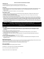
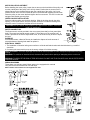
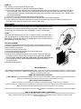
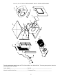
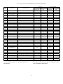
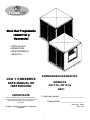
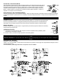
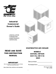
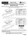
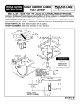
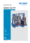
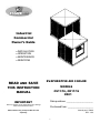
Industrial
Commercial
Owner’s Guide
• INSTALLATION
• OPERATION
• MAINTENANCE
• SERVICING
READ AND SAVE
EVAPORATIVE AIR COOLER
MODELS
CS11/16, CD11/16
CD21
THIS INSTRUCTION
MANUAL
IMPORTANT
Note any damage on the freight bill, as any damage
claim must be filed with carrier.
Date purchase: _____________________
Purchased from: ____________________
Motor, Motor Pulley, Pump and Belt are sold
separately
Manual part # 70888
REV. 1/06
1
INSTALLATION OF EVAPORATIVE COOLERS
PREPARATION
1. All electrical and duct work must comply with local and federal codes.
2. Make arrangements to get the cooler from ground to roof (crane, hoist, etc.).
LOCATION
1. Cooler should not be mounted near exhaust openings or vent pipes where fumes and odors can be drawn into cooler.
2. Ensure mounting surface is strong enough to support the cooler. Operating weight will be much heavier than
shipping weight.
3. Locate cooler so that fresh air is drawn in; air is not recirculated.
ROOF MOUNT UNITS
1. Select the location, taking into account roof construction and duct requirements. If rafters are cut when the roof
opening is cut, be sure to strengthen them.
2. Purchase or construct a platform to provide a level, mounting surface for the cooler. Always mount the cooler
high enough to allow easy access to the drain fitting.
3. Measure cooler or use the spec sheet to determine size of platform. Platform must be located so that the discharge
opening of the cooler is in line with the ductwork. On pitched roofs, the platform frame may be covered with galvanized
sheet steel or other weatherproof materials. An opening or removable panel must be left to allow access to the drain
fitting. On down discharge coolers the duct should be fastened to the platform collar before cooler is set in place. The
duct should have a standing flange for the cooler discharge opening to fit. Flash and seal the duct and roof opening to
provide weather tightness.
CAUTION: TO AVOID RISK OF FIRE, ELECTRICAL SHOCK, OR SERIOUS PERSONAL INJURY, BE SURE TO
DISCONNECT POWER FROM UNIT BEFORE CLEANING OR SERVICING.
WARNING: TO REDUCE THE RISK OF FIRE OR SHOCK; DO NOT USE THIS FAN WITH ANY SOLID STATE SPEED
CONTROL DEVICE.
DUCT WORK
1. The most important rule to follow when designing duct work is: AN EVAPORATIVE COOLER DEPENDS UPON
A LARGE VOLUME OF AIR COMING OUT OF THE DUCT WORK AT HIGH VELOCITY IN ORDER TO COOL
PROPERLY.
2. Do not “reduce” the discharge opening of the cooler.
3. Do not undersize the duct work and make it much smaller than the discharge opening. (In most cases, air
conditioning duct work is too small for coolers.)
4. Extra long ducts cause static pressure and will reduce airflow. They also pick up heat and diminish the effect of
the cooled air.
5. The motor pulley may be adjusted to compensate for ductwork.
6. Sharp or abrupt bends hinder airflow.
7. Poorly designed ceiling diffusers will ruin a successful installation. Install diffusers that are designed for use with
evaporative coolers.
MOTOR INSTALLATION
After cooler is in place and level, remove the motor from the box and inspect for shipping damage. Ensure that the motor
voltage, phase and horsepower are correct. Mount motor on motor mount as shown.
Mount the motor using the slots that align the motor pulley and blower pulley.
BELT ADJUSTMENT
An improperly adjusted belt will greatly shorten motor life.
A deflection of ¾” with finger force will indicate proper adjustment.
Do not use the motor pulley to adjust belt tension.
Always use the motor mount to adjust the belt.
2
MOTOR PULLEY ADJUSTMENT
Before installing the motor pulley, loosen the set screw on the back side of the pulley and
turn the outside jaw of the pulley until it is fully closed. Position the set screw over the
closest flat spot in the thread and then open the outside jaw of the pulley 4 or 5 turns.
Position the set screw over the closest flat spot in the thread and retighten the set screw.
Place the pulley on the motor shaft and tighten the front set screw. The CD21 coolers are
equipped with double groove pulleys.
OVERFLOW PIPE INSTALLATION
Place the rubber washer onto the drain bushing. Slide the bushing through the drain
opening, in the cooler bottom, from the top side. Screw the nut onto the bushing from
under the cooler. Position the overflow tube in the bushing.
CAUTION: DO NOT HOOK THIS COOLER TO A WATER SOFTENER. THIS WILL
VOID THE WARRANTY.
WATER CONNECTION
The float mounts in a hole provided in the corner post (down draft) or front panel (side
draft). The water level should remain at least ½” below the top of the overflow tube. A
screw is provided in the float to adjust water level; or the float rod may be bent to adjust
the level.
BLEEDOFF
In hard water areas, a bleed off kit may be installed to dispose of small amounts of
mineralized water, allowing fresh water to replace it.
Reservoir
ELECTRICAL POWER
1. The installation of electrical wiring must conform to all local and federal codes and should be done by a certified
electrician.
2. Connecting the motor and/or pump to the wrong voltage will void the warranty.
Notice to Installer: The motor amperage must be set as close as possible to motor nameplate amps without the pump
running.
WARNING: To avoid risk of electrical shock, disconnect the power before opening or attempting service on this unit.
WARNING: TO REDUCE THE RISK OF FIRE OR SHOCK; DO NOT USE THIS FAN WITH ANY SOLID STATE SPEED
CONTROL DEVICE.
WIRING DIAGRAMS
Three phase; one and two speed. Motor starter to be equipped with overload
relay sized to accommodate motor full load amps.
Motor starters and overloads are not supplied with units.
BLACK
STRIPED
RED
BROWN
MOTOR
1
3
RED
GREEN
3
PUMP
115V SUPPLY
PUMP
SINGLE SPEED
DIAGRAM
3
START UP
After installing cooler and before filling with water:
1. Open windows and doors or other exhaust openings in building.
2. Turn on cooler and check amperage at the incoming white lead, using clamp on ammeter. If amperage reads above
motor name plate, refer to the motor pulley adjustment instructions (page 2) and open the pulley ½ turn. Restart
cooler and recheck amperage. If amperage reads below motor name plate, close the pulley ½ turn. Restart cooler
and recheck amperage.
3. Turn on water to cooler and ensure that connections do not leak.
4. Fill pan to ½” below top of overflow tube and ensure that the float cuts off water completely.
5. Turn the switch to cool and check that water is coming from the water trays and that the pads are wetting evenly.
There are screws at the top of the louvers to level the water trays.
MAINTENANCE
CAUTION: Turn off all electrical power to this unit before opening or attempting any service.
Occasionally inspect your cooler for leaks, loose belt, blocked water lines, correct
belt alignment or excessive residue buildup on the pads. Inspect cabinet for rust. If
rust spots appear, sand and paint with a high-grade, corrosion resistant paint.
OILING
Lube the blower bearings twice per year- 2-3 drops per bearing. Use SAE 20W or
30W, non-detergent oil on bearings with oil cups and standard bearing grease on
ball bearings. Oil the blower motor if it is equipped with oil holes. Some motors are
permanently lubricated at the factory.
PAD REPLACEMENT
It is best to change pads at the end of the season. When old pads (covered by
minerals and salts) are left in the cooler during the wet winter months, there is a
greater possibility for corrosion.
1. Remove the louver from the cooler.
2. Unhook pad retainers from the sides of the louver and remove.
3. Remove the old pad and discard.
4. Clean any dirt or sediment that has built up on louver. Inspect the water tray
and clean any dirt or sediment that has built up in the water slots. If louver
has rust spots, sand and paint with a high-grade, corrosion resistant paint.
5. Tuck new pad into louver, ensuring that there are no gaps to allow hot air
to bypass the pad
6. Replace the pad retainers.
LIMITED WARRANTY
This warranty is extended to the original purchaser only. It does not cover damages incurred during shipping or through accident,
neglect, or abuse by the owner. Essick Air Products does not authorize any person or representative to assume any other or different
liability in connection with this cooler.
TERMS AND CONDITIONS OF WARRANTY
The BOTTOM PAN is guaranteed against leakage due to rusting out for Five Years. All other original parts provided by Essick Air
Products are warranted against defects in material or factory workmanship for One Year.
EXCLUSIONS FROM THE WARRANTY
Essick Air Products is not responsible for incidental or consequential damage resulting from any malfunction.
Essick Air Products is not responsible for any damage occurring from the use of water softeners, chemicals, descale material, or if a
higher horsepower motor than what Essick Air Products recommends is used in the unit.
Essick Air Products is not responsible for the cost of service calls to diagnose cause of trouble, or labor charge to repair and/or replace
parts.
HOW TO OBTAIN SERVICE UNDER THIS WARRANTY
Contact the Dealer where you purchased the evaporative cooler. If for any reason you are not satisfied with the response from the
dealer, contact Customer Service Department: Essick Air Products Inc. 5800 Murray Street, Little Rock, Arkansas 72209.
Phone 1-800-643-8341
4
CS11/16, CD11/16 & CD21 REPLACEMENT PARTS / PIEZAS DE RECAMBIO
To order replacement parts, please call “The Cooler Hotline” at 1-800-643-8341. To ensure prompt service, have the
following information available.
Cooler Model #______________________________ Serial # ____________________________________
Manual # and Revision Date____________________ Purchased From_____________________________
5
CS11/16, CD11/16 & CD21 REPLACEMENT PARTS / PIEZAS DE RECAMBIO
CS11/16
CD11/16 & CD21
DESCRIPTION
DESCRIPCIÓN
PART NO.
NO. DE REF.
QTY.
CAN.
PART NO.
NO. DE REF.
QTY.
CAN.
1
FRONT
FRENTE
70697
1
N/A
***
2
BOTTOM
BLOWER HOUSING
(CS11/16)
CUTOFF
BANDEJA INFERIOR
70702
1
70681
1
CAJA DEL VENTILADOR (CS11/16)
70703
1
***
***
ITEM
3
4
LIMITADOR DE AIRE
70705
1
70694
1
BANDEJA SUPERIOR
500220
1
500219
1
MONTAJE DEL MOTOR (CS/CD11/16)
70686
1
70686
1
7
TOP
MOTOR MOUNT
(CS/CD11/16)
WATER DISTRIBUTOR
DISTRIBUIDOR DE AGUA
512522
1
512523
1
8
BLOWER BRACE
SOPORTE DEL VENTILADOR
500852
2
500852
2
9
CENTER POST
POSTE CENTRO
501466
3
501466
4
10
PAD RETAINER
SUJETADOR DE LOS FILTROS
500603
6
500603
8
11
FILTER
FILTRO
524093
6
524093
8
12
LOUVER
LA REJILLA
501352
6
501352
8
13
WATER TRAY
LA CHAROLA PARA AGUA
500677
6
500677
8
*
LOUVER ASSEMBLY
JUEGO DE REJILLA
503396
6
503396
8
14
CORNER POST
POSTE DE ESQUINA
500098
1
500098
2
15
WATER HOSE
MANGUERA DEL AGUA
598400
60”
598400
60”
16
PUMP BRACKET
ABRAZADERA DE LA BOMBA
70488
1
70488
1
17
OVERFLOW KIT
EQUIPO DE DESBORDIMENTO
515100
1
515100
1
18
FLOAT VALVE
VÁLVULA FLOTADORA
524198
1
524198
1
5
6
19
SET COLLAR
COLLAR FIJO
501242
2
501242
2
20
BLOWER WHEEL
EL SOPLADOR LA RUEDA
70640
1
70640
1
21
BLOWER SHAFT
EJE DEL VENTILADOR
70672
1
70672
1
22
KEY
CHAVETA
589041
2
589041
2
23
POLEA DEL VENTILADOR
583095
1
583095
1
POLEA DEL VENTILADOR (CD21)
SURCO DOBLE
583018
1
583018
1
24
BLOWER PULLEY
BLOWER PULLEY
DOUBLE GROOVE
(CD21)
BEARING (CS/CD11/16)
CONJINETE (CS/CD11/16)
583005
2
583005
2
24
BEARING (CD21)
CONJINETE (CD21)
583001
2
583001
2
25
BEARING ANGLE
BLOWER HOUSING
(CD11/16 &21)
MOTOR MOUNT (CD21)
SOPORTE PARA COJINETE
514498
2
514498
2
CAJA DEL VENTILADOR (CD11/16 &21)
***
***
70692
1
MONTAJE DEL MOTOR (CD21)
***
***
512491
1
DEFLECTOR
N/A
506605/115V
506606/230V
***
501464
506605/115V
506606/230V
2
23
26
27
28
29
SPLASH BAFFLE
PUMP (SOLD
SEPARATELY)
BOMBA (se venden por separado)
Motor, pulley and belt sold separately.
*Louver assembly includes louver, water tray, pad and
pad retainers.
1
1
El motor, la polea y la banda se venden por separado.
*El juego de rejilla incluye la rejilla, la charola para agua,
filtro y sujetadores de los filtros.
6
Guía Del Propietario
Industrial y
Comercial
• INSTALACIÓN
• OPERACIÓN
• MANTENIMIENTO
• SERVICIO
LEA Y CONSERVE
ENFRIADOR EVAPORATIVO
MODELOS
CS11/16, CD11/16
CD21
ESTE MANUAL DE
INSTRUCCIÓN
IMPORTANTE
Anote cualquier daño en el recibo del transporte.
Cualquier demanda de daños por transporte se debe
presentar directamente con la compañía de
transportes.
Fecha de compra: _____________________
Comprado de: ____________________
Manual No. 70888
REV. 2/06
El motor, la polea y la correa se venden por
separado.
1
INSTALACIÓN DEL ENFRIADOR EVAPORATIVO
PREPARACIÓN
1. Todo el trabajo eléctrico y de los conductos debe cumplir con los códigos locales y federales.
1. Haga los arreglos necesarios para subir el enfriador al techo (grúa, polea, etc.).
UBICACIÓN
1. No instale el enfriador cerca de salidas de extractores o de tubos de ventilación para evitar que los humos y los olores penetren el
enfriador.
2. Asegure que la superficie de montaje sea lo suficientemente fuerte para soportar el peso del enfriador. El peso total del enfriador ya
instalado es mucho mayor del peso de transporte.
3. Coloque el enfriador de manera que entre aire fresco; pues el enfriador no recircula el aire.
UNIDADES DE MONTAJE PARA TECHO
1. Al seleccionar el lugar adecuado, tome en cuenta el tipo de construcción del techo y sigue las instrucciones para la instalación de
los conductos. Si al hacer el corte de abertura en el techo se afecta alguna viga de soporte, hay que reforzarla.
2. Compre o construya una plataforma de montaje para que el enfriador quede nivelado. Instale el enfriador dejando suficiente
espacio para permitir fácil acceso al sistema de desagüe.
3. Hay que medir el enfriador o ver la hoja de especificaciones para determinar el tamaño de la plataforma. La plataforma debe
estar colocada de manera que la abertura de desagüe del enfriador este alineada con los conductos. En techos con
inclinación, la estructura de la plataforma puede recubrirse con lámina de acero galvanizado o con otras materiales a prueba de
agua. Hay que dejar una abertura o un panel de quita para permitir el acceso al sistema de desagüe. En los enfriadores con
descarga hacia abajo, los conductos deben fijarse a la plataforma antes de poner el enfriador en su lugar. El conducto debe
tener una ceja para conectar la abertura de descarga del enfriador. Selle herméticamente la abertura en el techo donde entra
el conducto para que quede protegida de los elementos.
PRECAUCIÓN: PARA EVITAR RIESGO DE INCENDIO, CHOQUE ELÉCTRICO, O GRAVES DAÑOS PERSONALES, ASEGÚRESE
DE DESCONECTAR LA FUENTE DE PODER ANTES DE LIMPIAR O DAR SERVICIO AL ENFRIADOR
ADVERTENCIA: PARA REDUCIR EL RIESGO DE INCENDIO O CHOQUE ELÉCTRICO; NO USE ESTE ENFRIADOR CON NINGÚN
CONTROL DE VELOCIDAD DE ESTADO SÓLIDO.
CONDUCTOS
1. La regla mas importante a seguir al diseñar los conductos es: PARA QUE EL ENFRIADOR FUNCIONE ÓPTIMAMENTE ES
NECESARIO QUE EL CONDUCTO PERMITA PASAR UN GRAN VOLUMEN DE AIRE A ALTA VELOCIDAD.
2. No “reduzca” la abertura de descarga del enfriador
3. No permita que los conductos sean menores a la abertura de la salida de la descarga. (En la mayoría de los casos, los conductos
para aire acondicionado son demasiado pequeños para los enfriadores).
4. Conductos demasiado largos causan presión estática, reducen el flujo de aire y también absorben calor y disminuyen la efectividad
del aire frío.
5. Los ángulos o dobleces abruptos obstruyen el flujo de aire.
6. Los difusores de techo mal diseñados estropean una buena instalación. Instale difusores diseñados exclusivamente para uso en
enfriadores evaporativos.
7. La polea del motor puede ajustarse para compensar el sistema de conductos.
INSTALACIÓN DEL MOTOR
Una vez que el enfriador este en su lagar y nivelado, saque el motor de su caja y revise si hay daños de transporte. Asegúrese que el
voltaje del motor, fase y caballaje sean los correctos. Coloque el motor sobre la base para motor según lo mostrado. Use las ranuras
para alinear la polea del motor con la polea del ventilador.
AJUSTE DE LA CORREA
Una correa mal ajustada acortara la vida del motor. La tensión óptima de la correa es una desviación de ¾ pulgadas al hacer presión
con el dedo de la mano. No use la polea del motor para ajustar la tensión de la correa. Siempre use la base del motor para hacer el
ajuste de la correa.
2
AJUSTES DE LA POLEA DEL MOTOR
Antes de instalar la polea del motor, afloje el tornillo de fijación en la parte interna de la polea y gire la
parte exterior de la polea hasta que quede completamente cerrada. Coloque el tornillo de fijación en
la superficie plana más cercana en la rosca y luego gire 4 o 5 vueltas la parte exterior de la polea.
Coloque el tornillo de fijación en la superficie plana más cercana en la rosca y apriete el tornillo de
fijación. Coloque la polea en el eje del motor y apriete el tornillo de fijación delantero. El CD21 es
equipado con una polea de dos acanaladuras.
INSTALACIÓN DEL TUBO DE DESBORDAMIENTO
Coloque la arandela de goma en la boquilla de desagüe. Deslice de arriba hacia abajo, el boquilla a través de la abertura del desagüe
en el fondo del enfriador. Apriete la tuerca en el boquilla por la parte de abajo del enfriador. Coloque el tubo de desbordamiento a la
boquilla.
PRECAUCIÓN: NO INSTALE ESTE ENFRIADOR A NINGÚN SISTEMA DE SUAVIZADOR DE AGUA. ESTO CANCELARÁ LA
GARANTÍA.
CONEXIÓN DE AGUA
El flotador montaje en un agujero in el poste esquina (descarga debajo) o en el panel frente (descarga lateral).
El nivel de agua debe permanecer ½ pulgadas por debajo de la parte superior del tubo de desbordamiento.
Para ajustar el nivel de agua se puede usar el tornillo que esta en el flotador o doblar la varilla del flotador.
EQUIPO ANTISARRO
En áreas con agua dura se puede instalar un equipo antisarro para disolver pequeños residuos de minerales y
así permitir el flujo de agua fresca.
CORRIENTE ELÉCTRICA
1. La instalación del cableado eléctrico debe cumplir con todos los requisitos locales y federales y debe
efectuada por un electricista certificado.
2. Conectar el motor y/o bomba al voltaje equivocado cancelará la garantía.
DEPOSITO
Advertencia: Para evitar el riesgo de choque eléctrico, desconecte la fuente de poder antes de abrir o de iniciar el servicio de esta
unidad.
Noticia al Instalador: El amperaje del motor debe ser menos del amperaje que indica la placa del motor sin manejar la
bomba.
DIAGRAMAS DEL CABLEADO
Monofásico; una y dos velocidades
Trifásico, una y dos velocidades. El arrancador del motor debe tener protector de sobrecarga de la capacidad adecuada para recibir el
amperaje total del motor.
Los arrancadores y sobrecargas del motor no se proveen con las unidades.
3
INICIO DE OPERACIONES
Después de instalar el enfriador y antes de llenarlo con agua:
1. Abra las ventanas y las puertas u otras salidas de ventilación del edificio.
2. Encienda el enfriador y revise el amperaje en la línea de entrada blanca, usando un amperímetro. Si la lectura del amperaje es
mayor que el indicado en la placa del motor, vea las instrucciones del ajuste de la polea del motor (pagina 3) y abra la polea ½
vuelta. Vuelva a encender el enfriador y revise el amperaje otra vez. Si la lectura del amperaje es menor que el indicado en la
placa del motor, cierra la polea ½ vuelta. Vuelva a encender el enfriador y revise el amperaje otra vez.
3. Abra el suministro de agua hacia el enfriador y revise que no haya fugas.
4. Llene el deposito de agua ½ pulgadas por debajo de la parte alta del tubo de desbordamiento y asegúrese que el flotador corte
completamente el flujo de agua.
5. Ponga el encendido en frío y revise que el agua este saliendo de las charolas para agua y que los filtros se humedezcan
uniformemente. En la parte superior de las rejillas se encuentran los tornillos para nivelar las charolas de agua.
MANTENIMIENTO
PRECAUCIÓN: Desconecte la corriente eléctrica que alimente esta unidad antes de abrir o iniciar servicio.
Revise regularmente el enfriador por fugas, correas flojas, tuberías tapadas, alineamiento de la correa y exceso de sarro en los filtros.
Inspeccione si hay oxidación en el gabinete. Si aparecen manchas de oxido, líjelas y píntelas con pintura anticorrosiva.
LUBRICACIÓN
Lubrique los recipientes para aceite localizados en las chumaceras del ventilador. Use SAE 20W
o 30W aceite sin acción detergente. Lubrique el motor del ventilador si esté equipado con
receptáculos para aceite. Algunos motores están permanente prelubricados de fábrica.
CAMBIO DE FILTROS
Es el mejor cambiar los filtros al fin de la temperada. Cuando filtros viejos (cubiertos con los
minerales y las sales) se dejan en el enfriador durante los meses mojados del invierno, hay una
mayor posibilidad de la corrosión.
1.
2.
3.
4.
Retire la rejilla del enfriador.
Desenganche los sujetadores de los lados de las rejillas y quítelos.
Quite el filtro usado y deséchelo
Limpie todos los residuos y sedimentos que se hayan acumulado en las rejillas. Revise la
charlo para agua y limpie los residuos y sedimentos que se hayan acumulado en las
ranuras para agua. Si las rejillas tienen manchas de oxido, líjelas y píntelas con
pintura anticorrosiva.
5. Coloque el filtro nuevo en la rejilla, asegurando que no queden espacios que permitan que
pase aire caliente sin ser filtrado y vuelva a enganchar los sujetadores.
6. Recoloque las sujetadores.
GARANTÍA LIMITADA
Esta garantía se extiende solamente al comprador original. No cubre daños ocurridos durante el transporte por causa de
accidentes, negligencia o abuso por el propietario. Essick Air Products no autoriza a ninguna persona o representante para asumir
cualquier otra o diferente responsabilidad civil en relación a este enfriador.
TÉRMINOS Y CONDICIONES DE LA GARANTÍA
Garantía por cinco años sobre la cubeta de agua por filtraciones causadas por corrosión. Todas las demás piezas originales
suministradas por Essick Air Products están garantizadas contra defectos del material o de mano de obra por un año.
EXCLUSIONES DE LA GARANTÍA
Essick Air Products no es responsable por daños incidentales o consecuentes como resultado de un funcionamiento defectuoso.
Essick Air Products no es responsable por ningún daño causado por el uso de ablandadores de agua, productos químicos, material
anticorrosivo, o si se utiliza un motor con más caballos de fuerza de los recomendados por Essick Air Products para esta unidad.
Essick Air Products no es responsable por el costo de las visitas de servicio para diagnosticar la causa del problema, o los costos por
la mano de obra para reparar y/o reemplazar piezas.
COMO OBTENER SERVICIO BAJO ESTA GARANTÍA
Contactar al concesionario donde compró el enfriador evaporativo. Si por alguna razón no está satisfecho con la
respuesta del concesionario, contactar el Servicio de Atención al Cliente; Essick Air Products Inc.; 5800 Murray Street,
Little Rock, Arkansas 72209. Teléfono 1-800-643-8341.
4