1
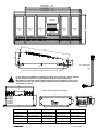
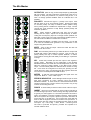
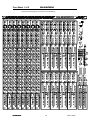
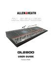
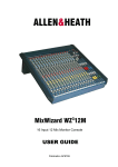
ALLEN&HEATH
GL2
GL2800M
800M
16 MIX WEDGE / IEM MONITOR CONSOLE
USER GUIDE
Publication AP6690
Limited One Year Warranty
This product is warranted to be free from defects in materials or workmanship for
a period of one year from the date of purchase by the original owner.
To ensure a high level of performance and reliability for which this equipment has
been designed and manufactured, read this User Guide before operating. In the
event of a failure, notify and return the defective unit to Allen & Heath Limited or
its authorised agent as soon as possible for repair under warranty subject to the
following conditions
Conditions Of Warranty
1. The equipment has been installed and operated in accordance with the
instructions in this User Guide
2. The equipment has not been subject to misuse either intended or accidental,
neglect, or alteration other than as described in the User Guide or Service
Manual, or approved by Allen & Heath.
3. Any necessary adjustment, alteration or repair has been carried out by Allen
& Heath or its authorised agent.
4. This warranty does not cover fader wear and tear.
5. The defective unit is to be returned carriage prepaid to Allen & Heath or its
authorised agent with proof of purchase.
6. Units returned should be packed to avoid transit damage.
In certain territories the terms may vary. Check with your Allen & Heath agent for
any additional warranty which may apply.
This product complies with the European Electromagnetic
Compatibility directives 89/336/EEC & 92/31/EEC and the
European Low Voltage Directives 73/23/EEC & 93/68/EEC.
This product has been tested to EN55103 Parts 1 & 2 1996 for use in
Environments E1, E2, E3, and E4 to demonstrate compliance with the
protection requirements in the European EMC directive 89/336/EEC.
During some tests the specified performance figures of the product
were affected. This is considered permissible and the product has
been passed as acceptable for its intended use. Allen & Heath has a
strict policy of ensuring all products are tested to the latest safety and
EMC standards. Customers requiring more information about EMC
and safety issues can contact Allen & Heath.
NOTE: Any changes or modifications to the console not approved by
Allen & Heath could void the compliance of the console and therefore
the user’s authority to operate it.
GL2800M User Guide AP6690 Issue 2
Copyright © 2007 Allen & Heath Limited. All rights reserved
ALLEN&HEATH Limited
Kernick Industrial Estate, Penryn, Cornwall, TR10 9LU, UK
http://www.allen-heath.com
Important Safety Instructions
WARNINGS -
Read the following before proceeding :
CAUTION
ATTENTION: RISQUE DE CHOC ELECTRIQUE – NE PAS OUVRIR
Read instructions:
Read and retain these safety and operating
instructions for future reference. Adhere to all warnings printed here and
on the console. Follow the operating instructions printed in this User
Guide.
Do not remove cover:
Operate the console and power units with
their covers correctly fitted. Disconnect mains power by unplugging the
power cord if the cover needs to be removed for setting internal options.
Refer this work to competent technical personnel only.
Power sources: Connect the console to a mains power outlet only
of the type described in this User Guide and marked on the rear panel.
Use the power cord with sealed mains plug appropriate for your local
mains supply as provided with the console. If the provided plug does not
fit into your outlet consult your service agent for assistance.
Power cord routing:
Route the power cord so that it is not likely
to be walked on, stretched or pinched by items placed upon or against it.
Grounding:
Do not defeat the grounding and polarisation
means of the power cord plug. Do not remove or tamper with the ground
connection in the power cord.
WARNING: This equipment must be earthed.
Water and moisture:
To reduce the risk of fire or electric shock
do not expose the console or its power units to rain or moisture or use in
damp or wet conditions. Do not place containers of liquids on surfaces
where liquid may spill into any openings.
Ventilation:
Do not obstruct the power supply heatsinks and
ventilation slots or position the console where the air flow required for
ventilation is impeded. If the console is to be operated in a flight case,
plinth or other furniture ensure that it is constructed to allow adequate
ventilation.
Heat and vibration:
Do not locate the console in a place
subject to excessive heat or direct sunlight as this could be a fire hazard.
Locate the console away from any equipment which produces heat or
causes excessive vibration.
Servicing:
Switch off the equipment and unplug the power
cord immediately if it is exposed to moisture, spilled liquid, objects fallen
into the openings, the power cord or plug become damaged, during
lightning storms, or if smoke, odour or noise is noticed. Refer servicing to
qualified technical personnel only.
Installation:
Install the console in accordance with the
instructions printed in this User Guide. Do not connect the output of
power amplifiers directly to the console. Use audio connectors and plugs
only for their intended purpose.
GL2800M
3
Allen & Heath
General Precautions
Damage
To prevent damage to the controls and cosmetics avoid
placing heavy objects on the control surface, scratching the surface with
sharp objects, or rough handling and vibration.
Environment
Protect from excessive dirt, dust, heat and vibration
when operating and storing. Avoid tobacco ash, smoke, drinks spillage,
and exposure to rain and moisture. If the console or its power unit
becomes wet, switch off and remove mains power immediately. Allow to
dry out thoroughly before using again.
Cleaning
Avoid the use of chemicals, abrasives or solvents. The
control panel is best cleaned with a soft brush and dry lint-free cloth. The
faders, switches and potentiometers are lubricated for life. The use of
electrical lubricants on these parts is not recommended. The fader and
potentiometer knobs may be removed for cleaning with a warm soapy
solution. Rinse and allow to dry fully before refitting them.
Lifting
To avoid injury to yourself or damage to the equipment take
care when lifting, moving or carrying the console.
Transporting
The console may be transported as a free-standing
unit or mounted in a purpose built flight case. We recommend that the
console is surrounded by shock absorbent foam to protect it from
damage during transit. Always use adequate packing if you need to ship
the unit. Protect the controls to avoid damage when moving the console.
Hearing To avoid damage to your hearing do not operate any sound
system at excessively high volume. This also applies to any close-to-ear
monitoring such as headphones and IEM transducers. Continued
exposure to high volume sound can cause frequency selective or wide
range hearing loss.
Important Mains plug wiring instructions.
The console is supplied with a moulded mains plug fitted to the AC
mains power lead. Follow the instructions below if the mains plug has
to be replaced. The wires in the mains lead are coloured in
accordance with the following code:
TERMINAL
WIRE COLOUR
European
USA/Canada
L
LIVE
BROWN
BLACK
N
NEUTRAL
BLUE
WHITE
E
EARTH GND
GREEN & YELLOW
GREEN
The wire which is coloured Green and Yellow must be connected to
the terminal in the plug which is marked with the letter E or with the
Earth symbol. This appliance must be earthed.
The wire which is coloured Blue must be connected to the terminal in
the plug which is marked with the letter N.
The wire which is coloured Brown must be connected to the terminal
in the plug which is marked with the letter L.
Ensure that these colour codes are followed carefully in the event of
the plug being changed.
GL2800M
4
Allen & Heath
Introduction
Welcome to the Allen & Heath GL2800M
GL2800M, the dedicated monitor version of the popular
GL series live sound mixing consoles. We have tried to keep this user guide brief and to
the point. Please read it fully before starting. Included is information on installing,
connecting and operating the console, panel drawings, system block diagram and
technical specification. For further information on the basic principles of audio system
engineering, please refer to one of the specialist publications and resources available from
bookshops, audio equipment dealers and the Internet.
Whilst we believe the information in this guide to be reliable we do not assume
responsibility for inaccuracies. We also reserve the right to make changes in the interest of
further product development.
We are able to offer further product support through our world-wide network of approved
dealers and service agents. You can also access our Web site on the Internet for
information on our full product range, resource downloads, our company pedigree, contact
details, assistance with your technical queries, or simply to chat about audio. To help us
provide the most efficient service please keep a record of your console serial number, and
date and place of purchase to be quoted in any communication regarding this product.
http://www.allen-heath.com
http://www.glseries.com
Contents
Warranty ....................................................................... 2
Important Safety Instructions ....................................... 3
General Precautions..................................................... 4
Introduction to this Guide............................................. 5
Panel Layouts............................................................... 6
System Block Diagram................................................. 7
Dimensions and Installation......................................... 8
Introducing the GL2800 .......................................... 9
Connecting Power........................................................ 9
Audio Connections..................................................... 10
Mono Input Channel .................................................. 11
16 Mix Sends.............................................................. 12
Mix Masters ................................................................ 13
Engineers Monitor System......................................... 14
Engineers Toolbox ..................................................... 15
Applications and Operating Tips ............................... 16
Specifications ............................................................. 21
Cue Sheets................................................................. 22
GL2800M
5
Allen & Heath
GL2800M
CONSOLE CONFIGURATION
SELECT USING A POINTED OBJECT
16 MIX WEDGE / IEM MONITOR CONSOLE
PHONES
+48V
3K
2k
3K
2k
4k
1k
9K
HM
HM
9K
HM
HM
9K
HM
HM
4k
1k
6k
700
9K
12k
500Hz
3K
2k
4k
1k
6k
700
12k
500Hz
3K
2k
4k
1k
6k
700
9K
12k
500Hz
3K
2k
4k
1k
6k
700
12k
500Hz
3K
2k
4k
1k
6k
700
9K
12k
500Hz
3K
2k
4k
1k
6k
700
12k
500Hz
3K
2k
4k
1k
6k
700
POLARITY
6k
700
9K
HM
A
9K
12k
500Hz
HM
12k
500Hz
ON
OSC/NOISE GENERATOR
ENABLE
LATCH
TALK SWITCH
OVERRIDE
PAD
0
20
30
40
-
GAIN
50
-14
6
HPF
100Hz
LM
-
+
400
500
200
500
2k
LM
1k
80Hz
2k
500
500
2k
LM
1k
80Hz
2k
500
2k
-
+
500
LM
1k
80Hz
2k
500
2k
-
+
LM
B
500
TALKBACK MIC
700
100
1k
80Hz
+
400
200
700
100
LM
-
+
400
200
700
100
1k
80Hz
-
+
400
200
700
100
LM
-
+
400
200
700
100
1k
80Hz
-
+
400
200
700
100
LM
-
+
400
200
700
100
1k
80Hz
-
+
400
200
700
100
60 40
1k
80Hz
2k
HF
C
-
12k
-15
1k
3k +15
4k
700
-
+
EQ IN
+
EQ IN
EQ IN
-
+
EQ IN
EQ IN
-
FOLLOW
IEM
+
EQ IN
EQ IN
TALKBACK
-15
15k
HPF
180
70
POLARITY
HPF
50
40
100
200
off
+15
50
40
100
15
400
200
off
POLARITY
HPF
100
15
400
POLARITY
HPF
50
40
200
off
50
40
100
15
400
200
off
POLARITY
HPF
100
15
400
POLARITY
HPF
50
40
200
off
50
40
100
15
400
200
off
POLARITY
HPF
100
15
400
200
off
MIN
50
40
100
15
400
MAX
OSC/NOISE
D
200
off
400
MIN
TB
400
35Hz
TB
TB
TB
TB
TB
TB
MAX
TB
MIX 1-8
PRE/POST FADER
MONO
STEREO
STEREO (LEV/PAN)
A
MUTE
MUTE
MUTE
MUTE
MUTE
MUTE
MUTE
MUTE
DIM
DIM
DIM
DIM
DIM
DIM
DIM
DIM
F AFL
ON
WEDGE
IEM
+15
-15
+15
WEDGE
80Hz
WEDGE
AFL
+16
+9
+6
+3
0
-3
-6
-9
-12
-16
-20
-30
1
OO
+6
C
10
MIX
2
OO
+6
OO
+6
5
R
WEDGE
AFL
IEM
MIX
PAN
WEDGE
AFL
IEM
EQ IN
STEREO
10
10
5
5
WEDGE
AFL
IEM
+16
+9
+6
+3
0
-3
-6
-9
-12
-16
-20
-30
WEDGE
AFL
IEM
10
10
5
5
WEDGE
AFL
IEM
+16
+9
+6
+3
0
-3
-6
-9
-12
-16
-20
-30
10
5
5
LATCH
AFL
IEM
10
B
WEDGE
AFL
IEM
3
C
1-8
MIX
POST
PRE
M1
MONO
STEREO
M2
0
0
0
0
0
0
5
5
5
5
5
5
5
5
STEREO
STEREO
MIX 9-12
+6
OO
10
R
10
10
10
10
M4
STEREO
10
10
MONO
STEREO
10
AFL
WEDGE
IEM
I
MIX
5
OO
PAN
+6
C
MIN
MIX
20
20
20
20
20
20
20
20
+6
OO
30
30
30
30
30
30
30
30
0
-12
OO
PAN
+6
C
00
00
00
00
00
00
00
00
MONO
STEREO
STEREO (LEV/PAN)
L AFL
WEDGE
IEM
AFL ROUTING
PFL
ON
PFL TO WEDGE MONITOR
ENABLE
MONO
STEREO
+6
AFL
WEDGE
IEM
M
STEREO
PRE/POST FADER
K
POST
PRE
L
7
POST
PRE
K
PFL
TRIM
R
MIX
AFL ROUTING
J
MAX
C
FOLLOW
IEM
6
L
STEREO (LEV/PAN)
AFL
WEDGE
IEM
MIX 13-16 CONFIGURE
MIX 13-16
STEREO
MONO
STEREO
J
POST
PRE
H
L
PRE/POST FADER
AFL
WEDGE
IEM
F
G
STEREO
I
E
5
0
4
POST
PRE
D
MUTE GROUPS
10
0
MIX
MIX 9-12 CONFIGURE
H
M3
PAN
G
GLOBAL
SETTINGS
TALK
IEM
+16
+9
+6
+3
0
-3
-6
-9
-12
-16
-20
-30
AFL ROUTING
EXT TB
MIX
STEREO
CONFIGURE
POST
PRE
E
PINK NOISE
1kHz OSC
1k
-15
L
AFL / PFL
FOLLOW IEM MONITOR
POLARITY
HPF
50
40
250
45
LF
HEADPHONES SOURCE
6k
500Hz
15
LM
-
+
EQ IN
POLARITY
HM
-
+
POWER
MIX
8
L
+6
OO
+16
+9
+6
+3
0
-3
-6
-9
-12
-16
-20
-30
R
1
MIX
2
3
4
5
6
7
8
9
STEREO
OO
PAN
+6
C
POLARITY
MIX
10
HPF
L
+6
OO
R
100
15
POLARITY
HPF
50
40
200
50
40
100
15
200
POLARITY
HPF
100
15
POLARITY
HPF
50
40
200
50
40
100
15
200
POLARITY
HPF
100
15
POLARITY
HPF
50
40
200
50
40
100
15
200
POLARITY
HPF
100
15
POLARITY
HPF
50
40
200
50
40
100
15
+16
+9
+6
+3
0
-3
-6
-9
-12
-16
-20
-30
200
L IEM R
MIX
off
11
400
off
400
off
400
off
400
off
400
off
400
off
400
off
WEDGE
PFL ACTIVE
STEREO
OO
PAN
TB
TB
TB
TB
TB
TB
TB
TB
MUTE
MUTE
MUTE
MUTE
MUTE
MUTE
MUTE
MUTE
M
+6
C
PFL ACTIVE
PFL
ON
MONO
MIX
12
L
OO
+6
OO
+6
R
MIX
DIM
13
DIM
WEDGE
STEREO
PAN
C
AFL
MIX
14
+6
OO
+16
+9
+6
+3
0
-3
-6
-9
-12
-16
-20
-30
MIX
15
STEREO
OO
PAN
10
+6
C
MIX
16
5
L
+6
OO
10
5
5
10
5
5
+16
+9
+6
+3
0
-3
-6
-9
-12
-16
-20
-30
10
5
5
MIN
MAX
AMPLIFIER
MIN
MAX
EXT
ON
EXT
ON
MUTE
MUTE
ENGINEERS WEDGE
AFL
IEM
10
EXT
IN
WEDGE
AFL
IEM
EXT
IN
DIM
WEDGE
AFL
IEM
10
DIM
WEDGE
AFL
IEM
+16
+9
+6
+3
0
-3
-6
-9
-12
-16
-20
-30
DIM
WEDGE
AFL
IEM
10
DIM
WEDGE
AFL
IEM
R
DIM
WEDGE
AFL
IEM
L
DIM
WEDGE
WEDGE OUT
400
IEM
+16
+9
+6
+3
0
-3
-6
-9
-12
-16
-20
-30
10
10
10
5
5
5
ENGINEERS IEM
BELT PACK
R
IEM OUT
MUTE
PK!
+6
0
SIG
M1
0
0
0
0
0
0
0
0
0
0
5
STEREO
5
STEREO
5
STEREO
5
STEREO
5
5
10
10
10
10
10
10
10
10
10
10
20
20
20
20
20
20
20
20
20
20
30
30
30
30
30
30
30
30
30
30
00
00
00
00
00
00
00
00
00
00
6
TRANSMITTER
0
5
M2
10
M3
HEADPHONES
20
M4
30
00
UNDER ARMREST
PFL
9
10
GL2800M
GL2800M
11
12
13
14
15
6
16
IEM
WEDGE
Allen & Heath
ALLEN&HEATH
INSERT
INSERT
INSERT
INSERT
8
IEM
GL2800M
INSERT
7
INSERT
6
INSERT
5
4
INSERT
INSERT
3
INSERT
INSERT
INSERT
INSERT
INSERT
INSERT
INSERT
INSERT
INPUT
INPUT
INPUT
INPUT
INPUT
INPUT
INPUT
INPUT
GND LIFT
GND LIFT
GND LIFT
GND LIFT
GND LIFT
GND LIFT
GND LIFT
GND LIFT
SPLIT
SPLIT
SPLIT
SPLIT
SPLIT
SPLIT
SPLIT
SPLIT
INSERT
2
1
L
W
INSERT
INSERT
16
R
INSERT
15
INSERT
14
INSERT
13
12
INSERT
INSERT
11
INSERT
10
9
LAMP
LAMP
IEM EXT IN
EXT TB/OSC
WEDGE EXT IN
L/M
MIX 8
MIX 7
MIX 6
MIX 5
MIX 4
MIX
3
MIX 2
MIX 1
R
WEDGE
R
MIX 16
IEM L
MIX 15
MIX 14
MIX 13
MIX 12
MIX 11
MIX 10
MIX 9
This device complies with Part 15 of the FCC Rules. Operation is subject to the following two conditions:
(1) this device may not cause harmful interference, and
(2) this device must accept any interference received, including interference that may cause undesired operation.
INPUT CHANNELS
MUTE GROUPS
PAD
POL
HPF
-20dB
2= +
HM
MUTE
W/IEM
L IEM AFL
R IEM AFL
LF
LO-CUT
FILTER
B POST-EQ
TIP= SEND
PRE-FADE
RING= RETURN
MIX9-16
INSERT
POLARITY
MIX
A PRE-EQ
FADER
+10dB boost
-2dBu
MUTE
2=+
-6dB
D PRE-FADE
E
MIX OUT
BAL
DIM
TB
C PRE-INSERT
DIRECT OUT
AFL
POST-FADE
FADER
0dBu
+4dBu
W
IEM
WEDGE AFL
LM
SPLIT
INSERT
2=+
EQ IN
+
-
LIFT
MUTE
AFL
LOGIC
M/ST
M4
MIX OUT
BAL
DIM
-6dB
LM
GAIN
IN
FADER
+10dB boost
M2
M3
HF
SERIAL NUMBER
HM
TB
METER
GL2800M
RING
MADE IN ENGLAND BY ALLEN & HEATH LIMITED
2 BAND EQ
-2dBu
EQ IN
M1
4 BAND EQUALISER
TIP
MIX1-8
INSERT
POLARITY
MIX
INSERT
SEND
RETURN
B (BACKUP)
DC POWER IN
LO-CUT
FILTER
PFL
PHANTOM POWER
48V
A
IEM/WEDGE
TB
W AFL
IEM AFL
GL2800M
16 MIX WEDGE / IEM MONITOR CONSOLE
PFL
PRE/POST
M/STEREO
MUTE GRPS
MIX 1-16
USE ONLY THE RECOMMENDED
ALLEN & HEATH POWER SUPPLY
AFL
LOGIC
M/ST
MODE 1-8
+4dBu
W
IEM
W/IEM
POST-FADE
AFL
SOLDER PAD OPTION
WEDGE AFL
MONO
STEREO
L IEM AFL
MIX1
MIX1-2
R IEM AFL
MIX2
L IEM R WEDGE
PAN
MIX3
MIX3-4
POST
MIX4
PFL MIX
PAN
PRE
IEM PFL
MIX5
MIX5-6
MIX6
PAN
MIX7
PHONES
WEDGE EXT IN
MIX7-8
ON
+
-
MIX8
PAN
PHONES OUT
FOLLOW IEM
W PFL
GLOBAL MIX SETTINGS
3
ENABLE
C
IEM EXT IN
MIX1-8
D
MONO/STEREO MODE
E
WEDGE/IEM AFL
F
MODE 9-12
1
TIP = LEFT
RING = RIGHT
R
PFL TRIM
MONO
MIX9-12
PRE/POST FADE
G
MONO/STEREO MODE
H
WEDGE/IEM AFL
STEREO
MIX9
PRE
MONO/STEREO MODE
K
WEDGE/IEM AFL
L
IEM
INSERT
FADER
-2dBu
MIX10
MIX11
2=+
INSERT
MIX11-12
MUTE
-2dBu
MIX12
PAN
IEM OUT
BAL
+10dB boost
PAN
MIX13-16
J
IEM AFL
MIX9-10
POST
I
PRE/POST FADE
2
M
ON
L/M
PRE/POST FADE
MONO
BAL
+4dBu
2=+
PHONES AFL
+4dBu
MODE 13-16
FADER
WEDGE AFL
+10dB boost
INSERT
WEDGE
-2dBu
BAL
MONO
MUTE
STEREO
MIX13
MUTE GROUPS
WEDGE OUT
2=+
DIM
MIX13-14
M1
POST
MIX14
PRE
MIX15
+4dBu
PAN
M2
M3
EXT TB OUT
EXT TB
MIX15-16
MIX16
M4
48V PHANTOM POWER
PAN
OFF
J1
TALKBACK
MIC IN
2= +
GL2800M
7
ON
J2
PINK NOISE
ON
+4dBu
DIM
1kHz OSC
GAIN
LEVEL
2=+
A
TB/OSC
PRESS TO TALK
B
LATCH
+
-
Allen & Heath
GL2800M-824 = 944
GL2800M-832 = 1171
GL2800M-840 = 1398
MASTER
SECTION
INPUTS
x8
INPUTS
x8
INPUTS
x8
INPUTS
x8
MASTER
SECTION
650
INPUTS
x8
5
62
168
6 34
58
640
DC POWER LEAD
19
9
2.8M
Allow access to additional under-armrest headphone socket
Do not obstruct the heatsinks or ventilation openings on the power unit. Ensure adequate
air flow around its surfaces. To avoid audible hum, buzz or other performance
degradation, do not place equipment that radiates strong electromagnetic fields such as
the power unit, other mains power supplies, amplifiers and computers next to or directly
underneath the console.
419
413
158
RPS11 Rack Mount Power Supply
230
483
115
368
Width
Depth
Height
Weight
GL2800-824
944mm (37.2”)
650mm (25.6”)
170mm (6.7”)
29 kg (63.8 lbs)
GL2800-832
1171mm (46.1”)
650mm (25.6”)
170mm (6.7”)
35 kg (77 lbs)
GL2800-840
1398mm (55”)
650mm (25.6”)
170mm (6.7”)
41 kg (90.2 lbs)
RPS11 PSU
482.6mm (19”)
235mm (9.25”)
135mm (5.31”)
9.5 kg (21 lbs)
GL2800M
8
100.0
132.5
57.2
167
465.1
Allen & Heath
Introducing the Allen & Heath GL28
GL2800M
00M
The monitor application has grown dramatically in recent times with the evolution of
multiple wedge and stereo in-ear systems which can quickly exceed the mix capability of all
but the most expensive consoles. The GL2800
GL2800M
00M adds a fully featured yet affordable
dedicated monitor console to the popular GL Series live sound range. It is compact, easy
to use, offers the best of analogue reliability and sound, and has a capability that rivals that
of much bigger and more expensive consoles. Mechanically similar to the GL2800
GL2800 with
its solid, individual card , nutted pot construction, it has the same space saving footprint
and flight case outline, includes a built-in mic splitter and provides no fewer than 16 mixes
plus a comprehensive dual output engineer’s wedge/IEM monitoring system.
•
24, 32, 40 and 48 channel frame sizes
•
16 mixes globally assigned as mono or stereo with level and pan
•
Built-in passive mic splitter with ground lift switching
•
All masters include polarity switch, swept HPF and 6dB dim function
•
Mix 1-8 include 2 band swept frequency output EQ
•
Engineer’s IEM and wedge monitors with faders, meters, inserts and XLR
•
IEM/wedge monitor external inputs for FOH comms and IEM rack monitoring
•
Mix AFL assignable to either wedge or IEM monitor
•
PAFL logic includes PFL override AFL, mono/stereo AFL, PFL to wedge enable
•
Headphones follow IEM mode, includes ¼” and 3.5mm jacks
•
Talkback with independent selection to all mixes and external output
•
Talk latch mode for use with switched hand held talkback mic
•
Built-in oscillator/ pink noise generator assignable to any mix output
•
Built-in dual supply combiner for additional power supply as a backup
•
4 mute groups
•
Solid individual card, nutted pot construction in a no nonsense all steel chassis
Connecting Power
Read the safety instructions provided with this console, and
A
DC POWER IN
B (BACKUP)
the warnings printed on the rear of the console and RPS11 power
unit. Check that your local mains supply voltage is the same as that
marked on the rear of the power unit.
Grounding For safety it is important that all equipment grounds
are connected to mains ground so that exposed metal parts are
prevented from carrying high voltage which can injure or even kill the
operator. Do not disconnect the ground connection in the mains lead.
Connect the DC power lead between the “DC OUT” on the
RPS11 and the “DC POWER IN A” on the GL2800M
GL2800M.
MAIN SUPPLY
BACKUP SUPPLY
Backup power supply
A second “B (BACKUP)” socket is
included for plugging in an optional backup RPS11 power supply.
This provides the reassurance of power supply dual redundancy. The
console uses diode combining technology so that both supplies can
be powered at the same time. One will automatically take over should
the other be switched off or stop working.
Switching the console on Turn the power amplifiers off before
switching the console and any other connected equipment on or off.
This prevents any unexpected clicks or thumps when the equipment is
powered up.
GL2800M
9
Allen & Heath
XLR female plug
TS jack plug
Tip
Sleeve
2
3
1
RCA phono jacks
XLR male plug
TRS jack plug
Sleeve
1
3
2
Tip
Ring
3
1+3 = 12V
OUTPUT
INPUT
XLR male socket
XLR female socket
1
2
2
1
1
PIN 2 = HOT
3
3
1=ground 2=hot +
BALANCED
Female XLR plug
4 = 0V
LAMP
2=hot + 1=ground
BALANCED
XLR male plug
3=cold -
3=cold -
UNBALANCED
UNBALANCED
INPUT / OUTPUT
HEADPHONES
UNBALANCED
Sleeve=ground
Ring=RIGHT
Tip=LEFT
link Ring to Sleeve
INSERT
BALANCED
Sleeve=ground
Ring=cold Tip=hot +
Sleeve=ground
Ring=return
Tip=send
UNBALANCED
Y-Adapter
Y-Adapter
RCA phono jacks
2 Outputs to 1 Input
adapter
1 Output to 2 Inputs
RCA PHONO CABLE
UNBALANCED
No !
UNBALANCED
INSTRUMENT CABLE
UNBALANCED
BALANCED
TRS JACK CABLE
BALANCED
Sleeve=ground
Sleeve=ground
Ring=cold (-)
Ring=cold (-)
Tip=hot (+)
TO
INPUT
Yes
Tip=hot (+)
2=hot (+) 1=ground
BALANCED
MIC CABLE
1=ground
BALANCED
XLR FEMALE
XLR MALE
TRS to XLR-F CABLE
Sleeve=ground
FROM
OUTPUT
3=cold (-)
3=cold (-)
BALANCED
2=hot (+)
1=ground
BALANCED
XLR FEMALE
2=hot (+)
3=cold (-)
Ring=cold (-)
Tip=hot (+)
2=hot (+) 1=ground
BALANCED
TRS to XLR-M CABLE
BALANCED
Sleeve=ground
XLR MALE
3=cold (-)
Ring=cold (-)
Tip=hot (+)
GL2800M
10
Allen & Heath
The Input Channel
INSERT
CHANNEL INPUT
Balanced XLR input pin 2 hot. Accepts mic or
line level signals. For unbalanced sources use a cable or adapter that
connects XLR pin 3 to pin 1.
INPUT
CHANNEL PREAMP
54dB gain range with 20dB pad to accept
signals from -60dBu to +14dBu nominal. Press PAD for hot signals up to
+34dBu max. Press HPF to switch in a 12dB/octave 100Hz lo cut filter.
Press POLARITY to invert the signal for working with a pin 3 hot source,
correcting a reverse wired cable, bottom miking a snare drum and so on.
Reversing polarity may help certain situations where feedback is a
problem.
GND LIFT
SPLIT
PHANTOM POWER Press +48V for phantom power via 6.8k ohm
PHANTOM POWER
48V
GAIN
PAD
IN
2= +
POL
-20dB
+
-
LIFT
resistors to pins 2 and 3 for microphones such as condensers which
require phantom powering.
WARNING: Do not connect unbalanced sources or cables to
the XLR input when 48V phantom power is selected. To avoid loud
clicks always turn the channel off by pressing MUTE when switching
+48V on or off, and when plugging or unplugging cables.
SPLIT
+48V
POLARITY
BUILT-IN MIC SPLITTER Passes the XLR input through to an XLR
PAD
0
20
30
40
GAIN
50
-14
6
60 40
HPF
100Hz
HF
12k
-15
1k
3k +15
4k
6k
700
HM
15k
500Hz
-15
180
70
LM
output to split the signal to another console such as FOH or recording.
This is a passive split. The GL2800M
GL2800M does not need to be turned on
for the split to work.
GND LIFT Disconnects the pin1 ground connection between the input
XLR and the split output XLR. Press this if there is a problem with a venue
ground loop causing audible hum when connecting the splitter to a
second console. To isolate the audio ground between the consoles make
sure you select all the channel ground lift switches.
INSERT A single 3-pole TRS jack carries the unbalanced insert signal
for each channel and main mix output. Tip = send, Ring = return, Sleeve
= common ground. The channel inserts are post-HPF, pre-EQ and
operate at 0dBu. Use these to patch in line level signal processing
equipment such as compressors, gates or outboard EQ. The wiring of a
suitable cable is shown in the diagram.
+15
PROCESSOR
250
45
35Hz
If you are working with separate monitor and FOH consoles then phantom
power may be supplied by either or both consoles without damage.
Typically the monitor console provides the power because the monitor
engineer would be closer to the stage patch.
400
RETURN
1k
INSERT
TIP
RING
LF
-15
+15
OUT
SEND
RETURN
SEND
GROUND
RETURN
SEND
IN
LINK RING TO SLEEVE TO UNBALANCE
80Hz
-15
+15
EQ IN
GL2800M
EQ 4 band channel EQ with swept frequency mids. The EQ is postinsert so that any inserted processing will be affected by these controls.
The channel pre-fade aux sends are configured post-EQ as standard.
11
Allen & Heath
The 16 Channel Mix Sends
The GL2800
GL2800M
00M features 16 mixes (aux sends). These are used for
combinations of stage wedge and in-ear monitor sends. The controls
are colour coded in pairs to quickly identify each mix. The mixes may
be configured as mono or stereo, and pre or post the channel trim
fader according to your requirement.
MIX
1
STEREO
OO
PAN
+6
C
MIX
2
L
+6
OO
R
MIX
3
STEREO
OO
PAN
4
L
+6
OO
WEDGE or IEM, MONO or STEREO ?
GLOBAL
SETTINGS
+6
C
MIX
R
MIX
5
STEREO
OO
PAN
+6
C
MIX
6
MIX
L
+6
OO
POST
PRE
MIX
7
STEREO
OO
PAN
E
+6
C
MONO
STEREO
MIX
8
L
+6
OO
R
AFL
WEDGE
IEM
F
MIX
9
STEREO
OO
PAN
1-8
D
R
+6
C
MIX
10
MIX 9-12
L
+6
OO
G
R
POST
PRE
MIX
11
STEREO
OO
PAN
+6
C
MONO
STEREO
12
L
+6
OO
R
MIX
AFL
WEDGE
IEM
I
13
STEREO
OO
PAN
+6
C
POST / PRE Default is post-fade mix (aux) send. Select
this switch to change to pre-fade.
MONO / STEREO
Default is mono send. Select this
switch to change to stereo send with separate pairs of level
and pan controls. Start with the pan controls set to their
centre detented position.
WEDGE / IEM AFL Each master AFL switch routes to
H
MIX
Before starting, configure how you want the console to work
by setting the GLOBAL SETTINGS switches in the master
section. These are identified with the letters ‘D’ to ‘L’. Use a
pen or pointed object to set these recessed switches. The
16 mixes may be configured in groups of 8, 4 and 4 to satisfy
many combinations:
either the engineer’s wedge or in-ear monitor. Default is AFL
routed to the wedge monitor. Select this switch to route AFL
to the engineer’s IEM monitor.
MIX
14
L
+6
OO
MIX 13-16
R
J
POST
PRE
MIX
15
STEREO
OO
PAN
+6
C
K
MIX
16
L
+6
OO
MONO
STEREO
R
MUTE
PK!
+6
0
SIG
AFL
WEDGE
IEM
L
MIX SENDS
These rotary controls adjust how much
channel signal is mixed to each of the console outputs.
They adjusts from fully off to +6dB boost. Unity gain 0dB is
marked at 3 o’clock position. Every second control has a
centre detent for operation as PAN when in stereo mode.
MUTE
Turns off all sends including pre and post fader.
Does not affect the channel insert.
6
FADER This is the channel trim control. Set to unity ‘0’
M1
0
position for normal operation. This is clearly marked with a
pointer. The fader allows adjustment affecting all post-fade
sends from the channel. +6dB boost is provided above ‘0’.
5
M2
10
M3
20
M4
STEREO (LEV/PAN)
MIX
30
the engineer’s monitor without affecting the mix outputs.
Selecting more than one PFL at the same time mixes those
signals together in the monitor. PFL overrides any current
mix AFL selection.
11
00
STEREO
OO
PAN
C
+6
MIX
PFL
12
L
+6
OO
R
MON (2x LEV)
MIX
13
STEREO
OO
PAN
C
+6
14
GL2800M
OO
+6
METER
A 4 LED channel meter displays the pre-fader
signal level. ‘SIG’ lights when a signal level of -12dBu is
detected. ‘0’ lights when the nominal 0dBu level is reached,
and ‘+6’ at +6dBu. ‘PK’ lights when the channel pre-fade
signal is within 5dB of clipping. This gives you enough
warning to reduce GAIN before you hear signal distortion.
MUTE GROUPS
MIX
L
PFL Press PFL to listen to the pre-fade channel signal in
R
Press these switches to add the
channel to Mute Groups 1 to 4 as required. Press the master
mute switch to mute all channels assigned to that group.
12
Allen & Heath
The Mix Master
OUTPUT EQ (MIX 1-8 only) 2 band swept frequency peak/dip EQ
3K
2k
3K
2k
4k
1k
4k
1k
6k
700
6k
700
9K
HM
12k
500Hz
-
HM
POLARITY
-
500
500
700
100
1k
80Hz
+
400
200
700
100
12k
500Hz
+
400
200
LM
9K
2k
LM
with in/out switch. Use this to adjust the overall sound of the mix, for
example to satisfy the preference of a performer using in-ears, or to
notch out wedge speaker feedback when an outboard EQ is not
available.
1k
80Hz
2k
-
+
Reverses the signal +/- polarity of the output. Start
with the switch in its up (non-inverted) position. Pressing the switch
for reversed polarity can help in situations where speaker wiring
errors, phasing effects or feedback is experienced on stage. Use the
console pink noise generator to help identify speaker polarity and
interaction problems.
HPF
-
+
EQ IN
EQ IN
POLARITY
HPF
40
100
15
POLARITY
HPF
50
200
off
400
Swept frequency 12dB/octave high pass (low cut) filter
affecting the mix output. Adjust from off (full response) to 400Hz.
Cutting the low frequency response of wedge monitor speakers can
help clean up the stage sound and avoid wasting amplifier power on
low end sounds and bleed not needed in the monitors.
50
40
100
15
200
off
400
TB
TB Enables the talkback / oscillator to the mix output. You can talk
to or route the oscillator/noise generator to any combination of mix
outputs using these switches.
TB
MUTE
MUTE
MUTE
DIM
DIM
Turns off the mix output. Affects the meter but does not
affect the mix AFL function.
DIM This momentary switch lets you attenuate the mix output level
WEDGE
WEDGE
AFL
AFL
IEM
10
5
IEM
AFL
+16
+9
+6
+3
0
-3
-6
-9
-12
-16
-20
-30
10
5
0
0
5
5
20
Routes the post-fade pre-mute mix output to the engineer’s
monitor system. Depending on the configuration of the GLOBAL
SETTINGS switches, AFL feeds the console headphones monitor and
either the engineer’s wedge speaker or the IEM (in-ear) monitor
output. The associated yellow LED indicates which monitor is being
fed. If two mixes are configured as a stereo pair, pressing one AFL
checks that mix in mono, and pressing both AFL together checks the
mix in stereo in the headphones and IEM monitors.
METER
STEREO
10
by 6dB (half volume) while holding it pressed. This can help you
quickly identify and stop a monitor speaker feedback, or reduce
volume without moving the fader while you are talking to a performer
on stage.
10
20
12 LED bar output meter displays the signal at the mix
output XLR. Meter ‘0’ = XLR +4dBu output.
STEREO INDICATOR Green LED lights when the pair of mixes
have been configured for stereo operation using the GLOBAL
SETTINGS switches. In stereo mode, the associated channel sends
operate as level and pan controls, and AFL can provide L only, R only
or stereo LR checking of the mix.
FADER A 100mm fader provides accurate control of the mix output.
30
00
1
GL2800M
30
00
2
INSERT Each mix is provided with an insert socket for patching in
an outboard signal processor. When working with stage speakers this
is typically a 31 band graphic or a multi band parametric EQ used for
ringing out feedback or tuning the speaker response. When working
with in-ear systems this may be a dynamics processor with limiter to
protect the ears of the IEM user. AFL monitors the signal after the
insert so that the engineer can listen to the effect of the processor. A
single 3-pole TRS jack carries the unbalanced insert signal for each
mix output. Tip = send, Ring = return, Sleeve = common ground.
The insert is post-HPF and pre-EQ, pre-fader and operates at a
nominal -2dBu line level.
13
Allen & Heath
The Engineer’s Monitor System
The GL2800
GL2800M
00M provides three independent engineer’s monitor outputs. By setting
configuration switches the engineer can listen to each mix the way the performer hears it.
MONO WEDGE OUTPUT To feed a wedge
ENGINEERS EQ
WEDGE OUT
INSERT
WEDGE
AFL
IEM
M
PFL
ON
EXT
ON
AMPLIFIER
PFL
ENGINEERS WEDGE MONITOR
EXT IN
TALKBACK FROM FOH
speaker monitor placed next to the console. Use
the same type of speaker as those used for the
monitors on stage so that the engineer can check
the signal as it is heard by the performers. Includes
a pre-fade insert for patching in an outboard EQ to
let the engineer experiment with EQ changes before
adjusting the associated mix EQ heard by the
performer. Any mix AFL configured as WEDGE
using the GLOBAL SETTINGS switches will be
routed here. PFL overrides AFL in the wedge
output if the recessed PFL ON enable switch has
been set. An external input lets you add another
signal such as talkback from FOH or a prompt back
to the monitor engineer.
STEREO IEM OUTPUT
ENGINEERS IEM
ENGINEERS PROCESSOR
BELT PACK
IEM OUT
WEDGE
AFL
INSERT
IEM
FROM TX RACK MONITOR
OR
FROM WEDGE EXT IN
TRANSMITTER
EXT
ON
PFL
EXT IN
HEADPHONES
WEDGE
HEADPHONES AFL interrupted by PFL. The
FOLLOW
IEM
C
AFL
To feed the
engineer’s in-ear monitoring system, typically a
wireless IEM similar to those used by the
performers. In situations where IEMs are not being
used the output could be connected to feed a
stereo wedge monitor instead. Includes a pre-fade
insert for patching in an outboard processor to let
the engineer try out changes before adjusting the
associated mix processor heard by the performer.
Any mix AFL configured as IEM using the GLOBAL
SETTINGS switches will be routed here. PFL
always overrides AFL in the IEM output. An external
input lets you select another signal such as a
monitor return from a wireless in-ear transmitter
rack. The wedge ext input normals through the
TRS input sockets for FOH talkback to the in-ears if
nothing is plugged in.
wedge and IEM AFL signals are summed to feed
the headphones output. A recessed mode switch
changes the headphones source to follow the IEM
output instead. This provides a headphones output
for the IEM monitor, complete with two ¼” and one
3.5mm sockets ideal for plugging in a variety of
headphones including in-ear transducers.
IEM
PFL
XLR OUTPUTS Differential balanced pin 2 hot
outputs operate at +4dBu with +26dBu maximum.
INSERT
IEM
INSERT
L
W
R
LAMP
INSERTS 3-pole TRS jack unbalanced insert for
each monitor. Tip = send, Ring = return, Sleeve =
ground. The insert is pre-fader and operates at a
nominal -2dBu line level.
IEM EXT IN
EXT TB/OSC
WEDGE EXT IN
L/M
GL2800M
Balanced XLR pin 2 hot for
nominal 0dBu line level signal.
IEM EXT IN Unbalanced TRS jacks for line level
R
WEDGE
WEDGE EXT IN
R
IEM L
input. For a mono signal plug into the L/M input
only. With nothing plugged into these sockets the
wedge ext input is normalled through to both inputs
to provide a common source to both the wedge and
IEM monitors.
14
Allen & Heath
The Engineer’s Toolbox
The GL2800
GL2800M
00M provides a comprehensive combination of facilities
to help the monitor engineer set up and keep control of the multiple
wedge/in-ear stage environment. Includes the engineer’s monitors,
headphones sockets, talkback section, built-in oscillator/noise test
generator, mute group masters and the global settings configuration
switches.
PHONES
TALKBACK MIC
PHONES OUT Both a ¼” and a 3.5mm socket are provided here
for plugging in standard headphones and mini-jack ear pieces and inear sets. An alternative ¼” socket is provided under the armrest.
TALKBACK
MIN
MAX
TB MIC Plug in a cable or gooseneck vocal microphone to talk to
OSC/NOISE
MIN
the performers via their monitors. +48V phantom power is provided.
This may be disabled by resetting an internal jumper. Adjust the mic
level using the TALKBACK trim control.
MAX
PINK NOISE
1kHz OSC
A
ON
OSC/NOISE GENERATOR The generator is turned on or off
EXT TB
B
LATCH
GLOBAL
SETTINGS
TALK
1-8
MIX
D
MUTE GROUPS
POST
PRE
M1
using a recessed switch to protect it from accidental operation. When
you have finished using the generator turn it off to avoid test signal
during the show. Adjust the level using the OSC/NOISE trim control.
The test signal is routed to a mix output as soon as its associated TB
switch is pressed.
E
MONO
STEREO
M2
AFL
WEDGE
IEM
F
M3
MIX 9-12
G
POST
PRE
M4
PINK NOISE / 1kHz OSC Select either the pink noise or 1kHz
tone as the test source. Use the tone when calibrating equipment
levels. Use pink noise when testing speaker drivers and polarity.
H
MONO
STEREO
AFL
WEDGE
IEM
I
MIX 13-16
MIN
J
MAX
C
POST
PRE
FOLLOW
IEM
PFL
TRIM
K
0
MONO
STEREO
L
-12
+6
AFL
WEDGE
IEM
Routes the talkback/generator to the rear panel EXT
TB/OSC socket. Balanced line level XLR output to drive a long cable
run to a remote location, for example to communicate with the
engineer at the FOH console. The output could also be used to patch
the generator to test console channels or other audio equipment.
TALK Press this momentary switch to route the talkback mic to any
POWER
+16
+9
+6
+3
0
-3
-6
-9
-12
-16
-20
-30
output which has its TB switch selected. To prevent possible
feedback the engineer’s wedge output is dimmed (attenuated) by
20dB when TALK is pressed. The generator is dimmed by 12dB for
intelligibility, for example when talking to a monitor being tested.
+16
+9
+6
+3
0
-3
-6
-9
-12
-16
-20
-30
L IEM R
LATCH This recessed mode switch overrides the TALK switch to
WEDGE
PFL ACTIVE
PFL ACTIVE
M
PFL
ON
MONO
EXT
IN
EXT
IN
MIN
EXT TB
MAX
MIN
permanently enable the talkback mic when using a switched hand
held microphone. Simply activate the switch on the microphone when
you want to talk to enabled destinations. The TALK switch still
provides a manual dim function.
MAX
EXT
ON
EXT
ON
MUTE
MUTE
MUTE GROUPS Press one or more of these master switches to
mute all inputs assigned using the channel M1-4 switches.
HEADPHONES FOLLOW IEM Set this recessed mode switch
10
10
5
5
0
0
5
5
10
10
to change the headphones source to follow the IEM monitor system.
PFL TRIM
Adjust the PFL signal level to the headphones and
monitor outputs to match your average AFL level. Range from -12dB
to +6dB with centre detented 0dB position for normal operation.
Does not affect the PFL meter reading.
IEM MASTER
20
20
30
30
00
00
IEM
GL2800M
Provides fader, mute, pre-fade meters, mono
summing of the stereo signal and external input switch and level trim.
Selecting a channel PFL overrides any current AFL selection, indicated
by the PFL ACTIVE LED.
WEDGE MASTER
WEDGE
Provides fader, mute, pre-fade meter and
external input switch and level trim. Select the recessed PFL ON
switch if you want to check PFL in the wedge monitor. PFL overrides
any current AFL selection.
15
Allen & Heath
GL2800M Operating Tips
The following is a collection of brief application notes, hints and tips to
help the operator to get the most out of the uniquely capable
GL28
GL2800M
00M live sound monitor mixing console. They are written as
a concise reference to spark your imagination to creatively and
effectively deal with the many challenges faced in modern day mixing.
-40
-50
-60
-70
SIGNAL
DYNAMIC RANGE
-30
CLIPPING
HEADROOM
+20
+16
+12
+9
+6
+3
+1
0
-1
-3
-6
-9
-12
-16
-20
SIGNAL-TO-NOISE RATIO
NORMAL OPERATING RANGE
Gain Structure
-80
-90
NOISE
!
The term used to describe the gain (level)
matching of the signal through the audio system chain. Each item in
the equipment chain has its own optimum (‘nominal’) operating level
determined by its electrical circuits. If you overload it with a signal that
is too high then its output tries to produce more voltage than its power
rails can provide resulting in harsh sounding distortion as the audio
signal is ‘clipped’. If you work with a signal that is too low then you
are likely to hear the residual hiss of the circuits as the ‘noise floor’ is
amplified along with the signal. The optimum operating level is the
point at which the signal is high enough above the noise floor so that
the hiss is not heard (good ‘signal-to-noise’ ratio, the SNR), yet
provides enough space (‘headroom’) before clipping to allow for the
louder, dynamic musical moments without distortion. ‘Dynamic range’
specifies the maximum range between noise floor and clipping. It is
the sum of the SNR and headroom. The larger the figure the better…
less noise, more headroom, more forgiving to wide ranging signals.
A microphone produces a very tiny signal, for example -50dBu (a few
millivolts). This should be amplified by the channel preamp to the
optimum operating level of the console circuits, around 0dBu
(0.775V), well clear of the noise floor (typically less than -90dBu), and
with good headroom (typically clipping at greater than +20dBu). The
signal can pass through many stages which affect its level within the
console; the channel, its EQ, fader, pan, the mix head amp, inserted
EQ and processing, master fader, on to the main output. The output
XLR provides the professional standard +4dBu (1.23V) nominal level
to the next stage in the audio chain, typically a speaker processor
such as limiter or crossover, or straight to the amplifier. The amp
boosts this signal to tens of volts to move the speaker cones so
producing the audible sound.
To get the best performance from your system, it is important that you
set up the gain structure correctly within the console and also within
and between the connected equipment. Ideally, each circuit should
be set to clip at the same time if the signal became too hot, in other
words each would have similar headroom relative to its nominal
operating level. The resulting dynamic range is the difference
between the highest noise floor and the lowest headroom through the
system. The performance is only as good as the weakest link.
The GL28
GL2800M
00M provides comprehensive metering to check every
point within the console signal path. Use the channel meters and
PFL/AFL system to set the gains and mix levels to average around ‘0’
meter reading with usual peaks around ‘+6’. Reduce the gain if the
red ‘+16’ or ‘PK’ indicator lights.
Use the equipment meters to set each item within the system path to
operate at its nominal level. We advise that the speaker processor or
amplifier trims are set so that the console outputs can drive up to their
nominal ‘0’ level. It is a common mistake to set amplifier trims to
maximum sensitivity when this results in the console master faders
being operated at very low positions, with low meter readings, and
reduced dynamic range and therefore audible residual system hiss.
GL2800M
16
Allen & Heath
Using the Oscillator / Noise Generator The GL28
GL2800M
00M
includes a useful signal generator able to produce a pure 1kHz sine
wave tone, or a pink noise test source. This is invaluable in testing the
system components and setting up correct gain structure. The
generator can be routed independently to the various console outputs.
OSC/NOISE
MIN
MAX
PINK NOISE
1kHz OSC
A
ON
Use the 1kHz tone to line up the connected equipment. For example,
a mix output to an in-ear transmitter or effects send/return loop. Route
the tone to the mix you wish to align. Set the mix master fader to ‘0’.
Press the mix TB switch to route the tone to this mix. Turn up the
OSC/NOISE level until the mix meter reads ‘0’. Next, adjust the
destination equipment input trim so that its meter also reads ‘0’. The
connected equipment is now correctly aligned to the operating level of
the console. You can patch the tone to other equipment by enabling
the EXT TB switch and using the rear panel EXT TB/OSC output.
Use the Pink Noise generator to check the signal routing and
loudspeaker response. ‘Pink noise’ is a random signal that contains
all audio frequencies and is therefore a very good test source. Unlike
‘white noise’ which has equal energy per Hz and sounds like system
or inter-band tuner hiss, pink noise has equal energy per octave, a
response that matches the logarithmic way our ears perceive sound.
You can hear all the frequencies clearly from deep bass, through mid
to treble. This means you can route the noise to a speaker system
and quickly hear if one of the sub, mid or HF drivers is faulty. With the
noise sent to several speakers at the same time you can listen for
comb filtering, and the severe phasing effect which indicates that one
of the speakers may have its wires reversed. Adjust the swept
frequency mix HPF using the noise source to listen to the effect of
cutting the low frequencies in the monitors.
The GL28
GL2800M
00M signal generator is an invaluable tool for calibrating
and testing the system during setup. To prevent any unexpected
mishaps during the sound check or show, remember to disable it by
releasing the recessed ON switch once you have finished the testing.
We also advise that you always start the calibration with the
OSC/NOISE trim turned fully off so that you can bring it up gradually
without the risk of overloading the destination.
Using PFL / AFL
PFL
WEDGE
AFL
IEM
☺
If you suspect the insert
socket to be faulty or
intermittent through excessive
wear or contamination, test for
this by plugging in a jack with
its tip shorted to its ring
contact. This bypasses the
contact in the socket. Clean
using
suitable
electrical
contact cleaner.
The input channels provide PFL (pre-fade
listen) so that each source can be checked using the meters and
wedge/IEM monitors before you bring the channel fader up. You can
use PFL while the channel is muted to prevent the signal reaching the
monitors until you have checked it and are ready. All the mix outputs
provide AFL (after-fade listen) so that you can check the exact level
leaving the console. The AFL switch gets its source before the output
mute so that you can check the signal before you send it to its
destination.
Using Inserts The GL2800
GL2800M
00M channel inserts operate at 0dBu,
the output inserts operate at -2dBu. In practice this makes little
difference as long as the inserted equipment is intended for line level
operation (-6 to +4dBu). Simply set the gain through the device to
unity (0dB) with the bypass switch pressed (if available). With the
effect switched in, use the processor output level trim or make-up gain
to make any further adjustments needed. This keeps the gain
structure correct through the channel signal path. With nothing
plugged into the insert, the channel signal is routed through a
switching (‘normalling’) contact in the socket. As soon as a jack is
plugged into the socket the contact is opened and the signal path
broken so that the external device can be patched in series with the
signal.
RETURN
OUT
INSERT
TIP
RING
GL2800M
SEND
RETURN
SEND
GROUND
RETURN
SEND
17
IN
LINK RING TO SLEEVE TO UNBALANCE
Allen & Heath
Polarity
POLARITY
Refers to the positive (+) and negative (-) wires of a
loudspeaker or balanced audio connection. The console input
channels and mix masters include POLARITY switches which reverse
the + and – input connections. Applications include correcting for
reverse wired cables, correcting for microphone placement problems,
mixing two mics on a snare drum, one above the other below where
the diaphragms move in opposite directions, helping to reduce comb
filtering effects between speakers on stage, reducing interaction
between stage sound and the FOH PA, and in certain situations
helping to reduce feedback. Polarity is sometimes labelled ‘phase’ on
mixing consoles. Technically, ‘phase’ is not the correct term as it
implies a 180 degree time shift. Polarity simply reverses the wires. It
does not affect time. Before starting your mixing, check that all the
channel and mix polarity switches are correctly set, normally up (+).
Using the channel faders
The channels provide 60mm trim
faders. It is typical to mix monitors with their channel sends set postfade. This means you can use the channel fader as a master level trim
for that source feeding all the mixes. Before you start balancing the
mix set the channel faders to their marked ‘0’ point for normal
operation.
6
0
5
10
If you prefer, you can set all or some of the sends pre-fade so that
they are not affected by the fader. For example, you could set the IEM
sends pre-fade so that the personal mix to each performer is not affect
when you make global changes to all the wedge speakers to adjust
stage volume for a particular instrument.
20
30
00
Using the built-in mic splitter The GL2800M
GL2800M provides a
built-in passive mic splitter. Plug the stage sources into the monitor
console channel inputs. Connect the split outputs to the multicore
feeding the second console, typically FOH. Each console has
independent control of its sources. It is the same as using an XLR Ycable for one mic to feed two console channels. The GND LIFT switch
disconnects the pin 1 ground link between the input and split output
XLRs. Use this only if you experience audible hum due to a ground
loop problem associated with the wiring at your venue. If this is the
case you may need to select all the channel lift switches. Only in
extreme situations may it become necessary to consider using a much
more expensive transformer splitter solution to provide complete
isolation between the consoles.
Start with all LIFT switches
deselected.
INPUT
GND LIFT
SPLIT
Phantom power and the monitor console Either or both
the monitor and FOH console may provide the 48V phantom power
without any problem or damage to the equipment. The power is
routed to the XLR pins via 6.8k ohm resistors which limit current and
prevent damage. Decide before the sound check which engineer
shall be responsible for providing the power. Typically the monitor
engineer would switch the power as he/she would be on stage helping
set up the microphones. Ensure that both the FOH and monitor
console mic channels are muted while the mics are being plugged
and power switched.
+48V
+48V
POLARITY
30
6
20
60 40
30
50
- 14
6
60 40
30
50
-14
6
60 40
30
6
60 40
30
20
50
-1 4 6
60 40
30
50
- 14
6
60 40
30
+48V
PAD
0
20
40
GAIN
50
-14
6
60 40
HPF
100H z
POLARITY
PAD
0
20
40
GAIN
HPF
1 00Hz
POLARITY
PAD
0
40
GAIN
H PF
+48V
POLARITY
PAD
50
-14
100 Hz
+48V
PO LARITY
0
20
40
GAIN
HPF
100H z
+48V
PAD
0
20
40
GAIN
HPF
100Hz
POLARITY
PAD
0
20
40
G AIN
H PF
+48V
POLARITY
PAD
0
40
50
-14
+48V
POLARITY
PAD
0
20
GAIN
HF
HF
HF
HF
12k
1 2k
12k
12k
3k + 15
4k
HM
500Hz
-15
70
15 k
-15
LF
500H z
1k
+1 5
80H z
15k
- 15
70
LF
- 15
+1 5
L
R
+6
OO
+6
OO
PA N
C
+6
OO
C
MIX
+6
OO
PA N
C
6
STEREO
C
L
R
+6
OO
M XI
+6
C
L
+6
OO
L
R
+6
OO
+6
C
L
+6
OO
L
R
+6
OO
M XI
C
L
+6
OO
R
12
C
R
+6
OO
+6
OO
R
C
C
MIX
+6
OO
R
OO
P AN
MIX
R
+6
OO
+6
OO
6
0
M1
5
M2
6
0
M1
6
0
6
0
M3
0
M3
6
M3
R
+6
OO
OO
PA N
+6
C
16
R
+6
OO
L
R
+6
OO
MUTE
M1
6
0
MU TE
P K!
+6
0
SI G
M1
5
6
0
5
M2
10
M3
20
M4
C
L
15
M2
M3
+6
OO
PA N
14
S TEREO
M XI
L
PK !
+6
0
SIG
10
20
M4
R
5
M2
10
20
M4
M XI
M XI
+6
16
0
R
+6
OO
S TEREO
R
+6
C
MUTE
M1
L
13
C
OO
OO
PAN
+6
C
M XI
+6
OO
STER EO
MIX
OO
5
M2
10
20
M4
6
R
+6
OO
L
15
L
PK!
+6
0
S IG
+6
OO
PA N
12
L
PAN
14
MIX
MUTE
R
+6
OO
S TEREO
M XI
13
MIX
L
11
STER EO
R
+6
+6
C
M XI
+6
C
MIX
+6
C
16
R
+6
OO
M1
R
+6
C
OO
OO
P AN
MIX
L
P K!
+6
0
S IG
5
M2
10
20
M4
M1
5
M2
M3
R
+6
OO
+6
OO
OO
AN
L
15
MU TE
PK !
+6
0
SIG
R
+6
OO
14
16
L
MUTE
10
20
M4
R
+6
OO
L
PAN
12
L
MIXP
STER EO
OO
PA N
10
OO
MIX
+6
C
R
+6
OO
S TEREO
M XI
11
STER EO
R
+6
OO
OO
PA N
MIX
L
9
+6
C
MIX
13
+6
C
L
15
S TEREO
R
+6
OO
STER EO
MIX
+6
C
M XI
R
+6
C
MIX
N
14
16
L
PK !
+6
0
S IG
5
M2
10
M3
R
R
+6
OO
OO
MIXPA
MIX
+6
L
OO
12
L
S TEREO
R
+6
C
+6
OO
OO
PA N
STER EO
PAN
OO
AN
R
+6
OO
S TEREO
8
10
L
L
7
MIX
STER EO
C
M XI
R
+6
+6
OO
M XI
+6
C
9
MIXP
13
C
OO
OO
PAN
MIX
MUTE
P K!
+6
0
S IG
C
12
L
15
STE REO
+6
C
11
N
R
+6
OO
OO
MIX
+6
OO
MIX
+6
OO
PAN
14
+6
C
16
L
M UTE
M1
MIX
MIX
OO
PAN
MIX
R
+6
OO
R
+6
OO
STE REO
R
+6
STER EO
+6
C
16
L
C
OO
15
STEREO
L
13
L
MIX
15
16
P K!
+6
0
SI G
12
+6
OO
PAN
14
L
MIX
+6
C
MIX
STER EO
+6
OO
AN
14
R
+6
OO
OO
PA N
L
MIXPA
L
PAN
MIX
OO
S TEREO
PA N
8
OO
R
+6
OO
6
MIX
L
C
L
M XI
STER EO
10
S TEREO
C
7
P AN
MIX
11
C
+6
OO
MIX
STER EO
+6
OO
PA N
5
R
+6
9
+6
C
MIX
+6
OO
PAN
R
+6
OO
13
STEREO
MIXP
L
15
L
MIX
13
+6
OO
PA N
14
M XI
R
+6
OO
STE REO
MIX
12
L
MIX
13
M XI
S TEREO
L
11
C
+6
C
MIX
OO
M XI
4
PAN
OO
OO
S TEREO
M XI
6
L
R
+6
OO
R
+6
MIX
STER EO
R
+6
OO
10
C
L
STER EO
8
L
PA N
MIX
MIX
+6
OO
PAN
C
7
S TEREO
+6
OO
PAN
OO
+6
OO
+6
L
3
5
P AN
MIX
9
+6
C
R
+6
C
M XI
STER EO
MIX
+6
C
MIX
OO
R
+6
OO
MIX
12
L
M XI
S TEREO
L
11
AN
R
+6
OO
OO
R
+6
OO
PAN
10
STER EO
+6
OO
MIXP
L
STE REO
MIX
MIX
STEREO
L
L
R
6
+1 5
EQ IN
OO
PA N
4
STER EO
+1 5
-15
1
2
MIX
+6
-15
LF
S TEREO
M XI
MIX
P AN
MIX
8
9
+6
C
C
S TEREO
PA N
MIX
MIX
OO
+6
OO
7
R
+6
OO
10
11
+6
OO
PA N
L
PAN
MIX
C
OO
400
1k
80H z
+6
OO
+6
OO
AN
L
180 +1 5
25 0
35Hz
M XI
R
5
LM
+15
C
2
3
MIXP
70
45
MIX
MIX
STER EO
R
+6
MIX
+6
C
+6
OO
-15
15 k
EQ IN
OO
PAN
4
S TEREO
R
+6
OO
OO
PAN
STER EO
MIX
11
S TEREO
L
STE REO
8
R
+6
C
10
C
+15
-15
1
MIX
PA N
MIX
7
9
OO
P AN
MIX
C
MIX
MIX
STEREO
+6
OO
MIX
+6
C
N
OO
6
R
+6
OO
OO
PAN
8
9
OO
PA N
10
L
7
MIX
+6
OO
L
5
-15
LF
MIX
3
MIXPA
40 0
1k
6k
500Hz
180 +15
250
STER EO
+6
L
40
3k + 15
4k
700
HM
80Hz
+ 15
C
MIX
S TEREO
-15
70
35 Hz
EQ IN
OO
R
+6
OO
15k
45
LM
+ 15
- 15
2
4
PAN
- 15
1
STER EO
P AN
MIX
MIX
STE REO
LF
MIX
L
R
+6
OO
6
STER EO
MIX
9
M XI
C
L
MIX
R
+6
C
8
M XI
C
MIX
OO
P AN
MIX
S TEREO
+6
OO
PAN
STEREO
+6
OO
PAN
5
LM
400
1k
- 15
1k
6k
50 0Hz
18 0 + 15
250
35H z
3k +15
4k
700
HM
8 0Hz
+6
3
STE REO
- 15
70
45
+ 15
C
MIX
4
6
7
OO
PA N
8
R
+6
OO
MIX
MIX
MIX
7
M XI
L
15k
EQ IN
OO
PA N
MIX
MIX
STER EO
+6
OO
+ 15
- 15
S TEREO
2
R
+6
OO
6
S TEREO
C
L
5
P AN
MIX
M XI
+6
OO
PAN
MIX
- 15
1
+6
3
R
LF
80H z
MIX
R
+6
4
+6
OO
LM
500H z
1k
-15
1k
6k
HM
400
35H z
3k + 15
4k
70 0
180 + 15
2 50
45
+15
C
MIX
STER EO
+6
OO
AN
L
5
S TEREO
L
- 15
1 5k
EQ IN
OO
PAN
2
OO
MIX
+15
-15
1
MIX
3
STEREO
R
+6
OO
-15
LF
80H z
-15
1k
6k
70
4 00
1k
3k + 15
4k
500H z
180 +15
250
35Hz
STE REO
2
R
4
L
5
LM
- 15
1k
700
HM
MIX
+6
C
MIX
MIX
MIXP
4
M XI
M XI
L
3
70
45
+ 15
OO
PAN
MIX
S TEREO
M XI
C
-15
15k
EQ IN
1
STER EO
+6
OO
2
3
+ 15
-15
MIX
STEREO
P AN
MIX
M XI
-15
LF
+ 15
1
C
400
1k
6k
500Hz
180 + 15
250
EQ IN
MIX
+6
OO
PA N
2
-15
70
35 Hz
3 k +15
4k
700
HM
80Hz
- 15
EQ IN
1
M XI
15k
45
LM
+ 15
80 Hz
-15
M XI
S TEREO
M XI
500 Hz
1k
-15
1k
6k
HM
400
35H z
3k +15
4k
7 00
180 + 15
250
45
LM
-15
1k
6k
HM
400
35Hz
3k + 15
4k
700
180 +1 5
25 0
45
LM
- 15
1k
6k
60 40
100Hz
HF
12k
- 15
6
H PF
HF
12k
1k
50
-14
10 0Hz
HF
12 k
700
30
GAIN
HPF
100H z
HF
12k
10
M3
20
M4
20
M4
30
30
30
30
30
30
30
30
00
00
00
00
00
00
00
00
PFL
PFL
GL2800M
PFL
PFL
PFL
PFL
P FL
Zero the console
Before starting the sound check it is good
practice to ‘zero’ the console by setting all its controls to a sensible
starting condition. Check that the GLOBAL SETTINGS and all other
mode switches are correctly set for your application. Set all GAIN, EQ
and PAN controls mid, faders off, TALKBACK and OSC/NOISE levels
off, TB enable switches off, PFL and AFL off, and all other switches up.
If you have configured stereo mixes start with their pan controls (even
numbered sends) set to their centre detented position. Make sure the
osc/noise generator is turned off. Cue Sheets are provided at the rear
of this guide for you to copy and log your control settings. This can
also be downloaded from our web site.
PFL
18
Allen & Heath
Stage wedge speakers
The type and position of the floor
wedge speakers used for stage monitoring are critical to both meeting
the performers needs and keeping stage noise under control. Use a
speaker designed for the monitor application and with adequate
power handling for the type of show. Know the directional response
of the microphones being used as this can determine the optimum
position of the speakers to minimise feedback. Ensure the speaker is
as close as possible to and angled up to face the performer.
The engineer’s wedge speaker
Use the same type of
speaker as used on stage for the performers. To help you hear the
mix as the performer does, position this in a similar way to those used
on stage, on the floor angled up towards you.
Ringing out the wedges
To avoid problems take care to
position each mic and speaker correctly. Use an EQ, typically 31
band graphic, inserted into each wedge mix. Start with the EQ set flat.
Sweep the console mix HPF to filter out unnecessary low frequencies.
Restricting the low end in the wedges can improve the overall stage
sound and prevent the amplifiers wasting energy. It is likely that there
will already be a strong low frequency presence from the back line.
Get a colleague to help with this process. Ring out each monitor by
carefully turning up the level until feedback just starts. Have someone
talk, shout or sing into the mic as this may stimulate further feedback.
Find and cut back that frequency a few dB on the EQ. Turn up the
level and find the next feedback ring. Do this for 2 or 3 frequencies
and do not cut more than 3 to 6dB where possible. Avoid using the
EQ to boost frequencies. Excessive use of the EQ may reduce the
feedback but may also destroy the intelligibility of the mix. While
finding the feedback it helps to simulate how the mic will be used
during the show. For example, cup the mic with your hand, present
your open mouth close to its grille, walk around the stage if the
performer does this. Certain ‘props’ such as sunglasses, costumes
and hats may stimulate feedback. Once you have completed the
process listen to your voice or a signal through the speaker to make
sure that the overall tone is good. A monitor that has been effectively
tuned in this way should provide plenty of GBF (gain before feedback)
ready for the sound check and show.
Creating a wedge mix
To improve intelligibility keep the mix
as simple as possible with just vocals and specifically requested
sources. It is unusual to put everything into the wedge mix as it is
there to supplement the acoustic contribution of the instruments on
stage. Avoid reverb or other ambient effects in the wedges if possible.
To keep the stage level under control encourage the performers to
turn down or reposition the back line amplifiers if they are too loud.
Mono or stereo in-ear monitors
BELT PACK
TRANSMITTER
The majority of
professional closed ear IEM systems are capable of handling a stereo
mix. Stereo is known to provide the performer with a much more
comfortable listening environment. However, mono is still the more
common method simply because of the lack of compact affordable
consoles with a sufficient number of auxes or the ability to create true
stereo mixes. The space saving GL2800M
GL2800M changes all that with
its 16 mixes, true stereo level/pan capability and advanced engineers
stereo monitoring…
Adding ambience to an in-ear mix
Because the performer
wearing an in-ear monitor becomes isolated from the stage and
audience acoustics it is good practice to add some ambience to the
mix. A little stereo reverb can help, or better still, use a pair of ambient
pickup microphones placed at the side or front of stage. Condenser
mics are recommended. Plug these into a pair of channels and pan to
create the stereo spread required. It helps to EQ out the extreme low
and high frequencies to avoid distracting from the musical mix.
GL2800M
19
Allen & Heath
TALKBACK MIC
Monitoring many mixes
The GL2800M
GL2800M provides a dual
AFL monitoring system so you can check the stage wedge mixes in
your own floor wedge, and check the in-ear mixes using your own IEM
system or the console headphones. Before starting, decide which
mixes are to feed each type of monitor and then configure the
GLOBAL SETTINGS switches accordingly.
TALKBACK
MIN
MAX
A quick and easy IEM monitor
OSC/NOISE
MIN
MAX
PINK NOISE
1kHz OSC
A
ON
EXT TB
If you do not have a
dedicated engineer’s IEM system then simply select the headphones
FOLLOW IEM switch so that the console headphones output may be
used instead. In this mode the headphones follows the engineer’s
IEM monitor master fader. A 3.5mm socket is provided in addition to
the two standard ¼” sockets, ideal for plugging in the typical ear
pieces used.
Communicating with the performers
B
Use the built-in
talkback system to talk to individual or combinations of performers
through their monitors. You may find it more convenient to use a
switched, hand held microphone. In this case select the recessed
LATCH mode switch to bypass the console TALK switch.
LATCH
TALK
Communicating with the FOH engineer
EXT
IN
MIN
MAX
EXT
ON
M1
M2
M3
M4
Use the external
TB/OSC output to connect via the multicore to an input on the FOH
console. Press the EXT TB switch to enable talkback to this output.
The FOH engineer can route that channel or select PFL to his monitor
when communication is needed. For reverse communication the FOH
engineer can send a line level talkback signal from the FOH console
via the multicore to the GL2800
GL2800M
00M wedge EXT input XLR. Press the
EXT ON switch and adjust the level to listen to the FOH signal in your
wedge when needed. The same talkback return is routed to the IEM
monitor when nothing is plugged into its TRS jack inputs.
Using the mute groups
Use these to mute combinations of
input channels, for example those associated with different bands
playing in a festival. We recommend you set up one group to mute all
inputs. This provides a quick way to turn the mix off during
intermission or while you replug microphones on stage.
Turning the system on and off It is good practice to:
Think before you hit
the switch!
•
Turn the amplifiers on last and off first.
•
Mute channels before plugging cables,
instruments and switching phantom power.
•
Let equipment which has been stored in a damp or cold
place acclimatise in the venue first before po