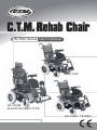
1
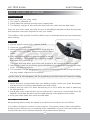
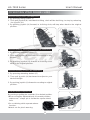
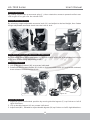
C.T.M. Rehab Chair
HS-7200 Series User's Manual
HS-7200
HS-7200B
ELEVATING+BED TYPE
HS-7200T TILTING
HS-7200 Series
User's Manual
Table of Contents
Introduction.........................................................................1
Electromagnetic Interference and Warnings..........................3
Safety Instructions...............................................................5
Initial Overview....................................................................6
Safe Driving Techniques.......................................................9
Operating your Rehab Chair..................................................11
Disassembling Your Rehab Chair.........................................15
Batteries and Charging.......................................................17
Maintenance,and Cleaning..................................................18
Troubleshooting..................................................................19
Accessories........................................................................21
Specification........................................................................22
HS-7200 Series
User's Manual
INTRODUCTION
C.T.M. is a professional and experienced manufacturer, that specializes in production of
Mobility Scooters and Power Chairs that are developed by a team of specialists with
outstanding design skills and competence.
The HS-7200 is an excellent chair that includes ergonomic features. It combines safety
and comfort and gives users extraordinary experience and convenience in operation.
With its thoughtful and people-friendly controller system, the user can easily achieve
360 degree turns with their finger tips.
This product is powered by the sealed, no water added, high performance and, most of
all, connectorless lead-acid battery, which ensures environmental safety and brings
convenience in disassembly and re-assembly.
Preface:
This User's Manual contains important information and know-how on operating and
maintaining the C.T.M. product. Please read it carefully before practicing with your new
chair, so that you comprehend the technical advantages of HS-7200
All assembly and maintenance should be performed after you fully understand the content
of this manual to avoid any hazard or damage to the Power Chair or human body.
Overhaul and adjustments must be undertaken by skillful maintenance staff following the
instructions provided in this booklet.
Any improper usage might lead to danger to the user or the chair. C.T.M. is/will not be
responsible for any after-effect resulting from failure to comply with this manual.
After unpacking, please inspect carefully for any defect or missing part.
Limitation In Transporting And Travelling:
1. When transporting HS-7200, please ensure the product is not scratched or damaged.
2. If a long trip is planned, please fully charge the batteries before use to prevent low
voltage during the trip.
All the contents in this manual including pictures, photo illustrations and text are all patented
and registered according to the constitution of R.O.C.. With no approval from C.T.M.
self-interpretation and duplication are strictly prohibited. (If any details in the manual are
going to be changed or added, C.T.M. will not notify previous owners of the modification.)
1
HS-7200 Series
User's Manual
We wish you an enjoyable riding experience.
If you have any questions, you can contact:
CHIEN TI ENTERPRISE CO., LTD.
No.13, Lane 227, Fu Ying Rd., Hsin Chuang,Taipei, Taiwan,
Tel : +886-2-2903-2987 Fax : +886-2-2903-8807
E-Mail : [email protected] http : //www.chienti.com.tw
or your local dealer:
2
HS-7200 Series
User's Manual
ELECTROMAGNETIC INTERFERENCE
AND WARNINGS
CAUTION: It is very important that you read this information regarding the possible
effects of Electromagnetic Interference on your power chair.
Powered wheelchairs and motorized scooters may be susceptible to electromagnetic
interference (EMI), which is interfering electromagnetic energy (EM) emitted from sources
such as radio stations, TV stations, amateur radio (HAM) transmitters, two-way radios,
and cellular phones. The interference (from radio wave sources) can cause the power
chair to release its brakes, move by itself, or move in unintended directions. It can also
permanently damage the power chair control system. The intensity of the interfering
EM energy can be measured in volts per meter (V/m). Each power chair can resist EMI
up to a certain intensity. This is called its "immunity level." The higher the immunity level,
the greater the protection will be. At this time, current technology is capable of achieving
at least a 20 V/m immunity level, which would provide useful protection from the more
common sources of radiated EMI. The immunity level of this product is 20 (V/m).
There are a number of sources of relatively intense electromagnetic fields in the everyday
environment. Some of these sources are obvious and easy to avoid. Others are not
apparent and exposure is unavoidable. However, we believe that by following the warnings
listed below, your risk to EMI will be minimized.
Electromagnetic Interference and Warnings:
The sources of radiated EMI can be broadly classified into three types:
1.Hand-held portable transceivers (transmitters-receivers) with the antenna mounted
directly on the transmitting unit. Examples include: citizens band (CB) radios,
"walkie talkie," security, fire, and police transceivers, cellular telephones, and other
personal communication devices.
Some cellular telephones and similar devices transmit signals while
they are ON, even when not being used.
2.Medium-range mobile transceivers, such as those used in police cars, fire trucks,
ambulances, and taxis. These usually have the antenna mounted on the outside of
the vehicle.
3
HS-7200 Series
User's Manual
3.Long-range transmitters and transceivers such as commercial broadcast transmitters
(radio and TV broadcast antenna towers) and amateur (HAM) radios.
Other types of hand-held devices, such as cordless phones, laptop
computers, AM/FM radios, TV sets, CD players, and cassette players,
and small appliances, such as electric shavers and hair dryers, so far
as we know, are not likely to cause EMI problems to your power chair.
Power Chair Electromagnetic Interference:
Because EM energy rapidly becomes more intense as one moves closer to the transmitting
antenna (source), the EM fields from hand-held radio wave sources (transceivers) are of
special concern. It is possible to unintentionally bring high levels of EM energy very close
to the power chair control system while using these devices. This can affect power chair
movement and braking. Therefore, the warnings listed below are recommended to prevent
possible interference with the control system of the power chair.
Electromagnetic Interference and Warnings:
Warnings
Electromagnetic interference (EMI) from sources such as radio and TV stations, amateur
radio (HAM) transmitters, two-way radios, and cellular phones can affect the power chair.
Following the warnings listed below should reduce the chance of unintended brake release
or power chair movement, which could result in serious injury.
1.Do not operate hand-held transceivers (transmitters-receivers), such as citizens band
(CB) radios, or turn ON personal communication devices, such as cellular phones,
while the power chair is turned ON;
2.Be aware of nearby transmitters, such as radio or TV stations, and try to avoid coming
close to them;
3.If unintended movement or brake release occurs, turn the power chair OFF as soon
as it is safe;
4.Be aware that adding accessories or components, or modifying the power chair, may
make it more susceptible to EMI; and
5.Report all incidents of unintended movement or brake release to the distributor listed
on the inside front cover of this manual. Note whether there is a source of EMI nearby.
Important Information
1.20 volts per meter (V/m) is a generally achievable and useful immunity level against EMI
(as of May 1994). The higher the level, the greater the protection.
2.The immunity level of this product is 30 (V/m).
4
HS-7200 Series
User's Manual
SAFETY INSTRUCTIONS
Safety is the main consideration when practicing with your chair. It is required that you
read and comprehend all the operating and safety instructions discussed in this manual.
And ensure your chair is correctly fitted and adjusted by your dealer or the prescribing
healthcare professional.
Make sure to engage the wheel locks before entering or leaving the chair. The wheel locks
are designed to prevent movement of the chair. It is preferable to ensure the front castors
are in the forward position before transferring in to or out of the chair. With the castors
in the forward position the wheel base of the chair is increased, therefore, offers more
stability.
DO NOT move forward in the seat while leaning forward out of the chair. If an object is
to be picked up from the floor, drive past it, then reverse so the front castors are in the
forward position. This gives the chair its greatest stability.
To maintain lateral stability do not reach further than the length of your arm. DO NOT
lean out of the chair as this could cause instability.
When transferring, DO NOT stand on the leg rests. Depending on the style of leg rests
either swing them away or fold them up before transferring.
When approaching a ramp, be sure of your own ability and your limitations in terms of
strength and endurance.
Before attempting a ramp the following basic safety rules should be considered:
1.
2.
3.
4.
Surface of the ramp: Is it too slippery?
Degree of incline: Is it too steep to attempt alone?
Length of ramp: Is it too long for your endurance?
Obstacles: Are there any obstacles on the ramp that would necessitate assistance?
Be very careful when going up or down steep inclines
If it becomes necessary to stop when going up an incline, special care must be taken to
avoid abrupt or sudden forward movement. During continuous forward movements, the
chair is capable of falling backwards.
Always keep the chair under control when going down a ramp or incline. Speed should
be controlled at all times.
The user in the rehab chair and a curb is encountered,
caution should be taken to prevent the user being thrown forward:
1. With both motors disengaged, go down the curb, rear wheels first; making sure that
the user is square to the curb so that the rear wheels go down together.
2. To go up a curb forward, verify both front wheels are up together. This must be
accomplished with the motors disengaged.
Also try to avoid going up multiple steps and using escalators. Use the elevator instead.
Please be aware that any adjustments on the rehab chair may affect the
handling and performance.
5
HS-7200 Series
User's Manual
INITIAL OVERVIEW
Before attempting to drive this rehab chair on your own, it is important that you familiarize
yourself with the controls and how they operate.
Handlebar
Padded Breathable Ballistic Nylon Back Rest
Super Responsive Digital Joystick
Support Brace
Charging Socket
Footrest Holder
Height Adjustable
Armrests
Carrier
Flip-up Armrests
2 High Torque Motors
Mated to Precision
Sealed for Life
Gear reducess
Manual Tilting
Battery Holder Knob
Fiber Glass
Reinforced Nylon
Leg Rests
Figure 1 - HS-7200 Rehab Chair Front View
Reclining Adjustable Knob
Battery Level Indicator
On/Off Switch
Speed Control
Button
Horn
Freewheeling
Level
Joystick
Suspension
Circuit
Breaker
Anti Tip Wheel
Battery Sliding Wheel Control Lever
Speed Indicator
Figure 3 - HS-7200 Rehab Chair Rear View
Figure 2 - HS-7200 Joystick
6
HS-7200 Series
User's Manual
INITIAL OVERVIEW
Before attempting to drive this rehab chair on your own, it is important that you familiarize
yourself with the controls and how they operate.
Handlebar
Padded Breathable Ballistic Nylon Back Rest
Super Responsive Digital Joystick
Support Brace
Charging Socket
Footrest Holder
Height Adjustable
Armrests
Carrier
Flip-up Armrests
2 High Torque Motors
Mated to Precision
Sealed for Life
Gear reducess
Fiber Glass
Reinforced Nylon
Leg Rests
Battery Holder Knob
Figure 1 - HS-7200T Rehab Chair Front View
Reclining Adjustable Knob
Battery Level Indicator
On/Off Switch
Speed Control
Button
Horn
Tilting
Button
Freewheeling
Level
Joystick
Suspension
Circuit
Breaker
Anti Tip Wheel
Battery Sliding Wheel Control Lever
Speed Indicator
Figure 2 - HS-7200T Joystick
Figure 3 - HS-7200T Rehab Chair Rear View
7
HS-7200 Series
User's Manual
INITIAL OVERVIEW
Before attempting to drive this rehab chair on your own, it is important that you familiarize
yourself with the controls and how they operate.
Adjustable Headrest
Support Brace
Super Responsive Digital Joystick
Charging Socket
Height Adjustable
Armrests
Footrest Angle
Adjustment
Flip-up Armrests
2 High Torque Motors
Mated to Precision
Sealed for Life
Gear reducess
Adjustable
Footpad
Battery Holder Knob
Fiber Glass Reinforced Nylon Leg Rests
Figure 1 - HS-7200B Rehab Chair Front View
Height Adjustable
Headrest Knob
Battery Level Indicator
On/Off Switch
Front View
Speed Control
Button
Horn
Elevating
Button
Battery Sliding
Wheel Control
Lever
Joystick
Circuit Breaker
Anti Tip Wheel
Speed Indicator
Suspension
Figure 2 - HS-7200B Joystick
Freewheeling
Level
Figure 3 - HS-7200B Rehab Chair Rear View
8
HS-7200 Series
User's Manual
SAFE DRIVING TECHNIQUES
Driving your Chair
Before sitting on your chair, verify:
1. The chair is switched off.
2. Swing away the armrests and leg rests if appropriate.
3. The battery charger is disconnected from both the chair and the wall outlet.
Once on your chair, make sure that you are comfortably positioned and that the leg rests
and armrests have been adjusted to suit your needs.
The position of the joystick should be within reach to eliminate hand and arm exhaustion
when driving.
To Begin :
1. Set the speed control of the chair to SLOW.
2. Press the "on / off" switch.
3. Allow two seconds to elapse before engaging the
joystick. This is a safety feature to prevent sudden
starts.
4. Push the joystick gently forward applying a steady
even pressure. The further you push the joystick,
Figure 4
the faster the chair will go.
The chair will stop when you return the joystick to the neutral or vertical position.
5. Directional control is achieved by gently swivelling the joystick in the direction you wish
to go. Pull back to reverse.
6. The controller can be programmed to give you the best feel for all driving situations
and only needs a light touch to respond.
In the case of an emergency, let the joystick go and the chair will come to a stop.
Safe Driving
1. Never drive at a speed greater than your ability to safely control your chair. Remember
that wet or loose surfaces need greater care and control.
2. Always turn the chair OFF when transferring on or off or while the chair is stationary
for long periods.
3. Avoid jerky stop / start motions as this will result in excessive current draw from the
batteries, increased tire wear and the rapid wearing of the gearbox and motors.
4. Keep your chair clean from sand and salt water.
Indoor / Outdoor Driving
When driving indoors keep the speed to a minimum to avoid the risk of collision.
For outdoor driving be cautious of wet surfaces, loose sand, large curbs and potholes.
A little practice will ensure you understand the capabilities of your chair and enable you
to overcome the most common obstacles encountered when driving.
9
HS-7200 Series
User's Manual
Chair Operation on surfaces that require Special Care
When driving up or down ramps it is recommended that the user:
1. Visually checks to see if the angle of the slope is less than 8 degrees.
2. Checks to see that the ramp surface is roughened to prevent slippage.
3. Ensures that the ramp surface is correctly in line with the tires and is wide enough to
allow the tires to pass freely along the ramp.
If the ramp meets these conditions, it is recommended that the user drives the wheelchair
slowly up or down the ramp, ensuring that the chair is driven in the centre of the ramp
tracks. If possible, have an assistant monitor the chairs' progress, and prevent tipping
of the chair by holding the push handles at the back of the seat.
If the ramp does not meet these conditions, it is recommended that alternative
methods for climbing and descending be found.
Chair Response
Should the chairs' response not be to your satisfaction, ask your dealer to adjust the
program to a level at which you are comfortable. This program can be altered at
anytime to either increase the response rates in line with your improved motor skills
or to lower the rates to a level at which you feel comfortable and in control.
Curbs
It is recommended that before the user attempts to climb or descend a curb that the user
visually checks the height of the curb to ensure that it does not exceed 1" in height.
If the curb height is less than 1", the user should approach the curb at right angles to
the curb line at a slow speed, climb or descend the curb slowly so as to keep the chair
under control. When climbing the curb, the user may find it easier to reverse the chair
up the curb.
If the curb height is greater than 1", it is not recommended that the user climb or descend
the curb.
Steep Slopes
When the rehab wheelchair is to be operated up and down steep slopes, it is recommended
that the user:
1. Visually checks to see if the angle of the slope is less than 8 degrees.
2. Checks that the slope surface is roughened to prevent slippage.
If the slope meets these conditions, it is recommended that the user approach the slope at a
slow speed, keeping the chair under control at all times. It may be preferable to track across
the slope so as to decrease the steepness of the descent providing that the surface of the
slope is wide enough and suitable to prevent slippage.
10
HS-7200 Series
User's Manual
OPERATING YOUR REHAB CHAIR
Electrical Tilting Function (HS-7200T Only)
1. By pressing tilting button (F)
2. Then pull joystick (H) backward to tilting, chair will be declining, to stop by releasing
the joystick (H).
3. By pushing joystick (H) forward, to inclining chair, will stop when back to the original
position.
A
B
G
D
E
F
H
C
Figure 6
Figure 5
Electrical Reclining 180 Degree Function (HS-7200B Only)
1. By pressing reclining button (F)
2. Then pull joystick (H) backward to reclining to any
angles.
3. By pushing joystick (H) forward to inclining chair
back to its original position.
Figure 7
Electrical Elevating Function (HS-7200B Only)
1. By pressing elevating button (G)
2. Then pull joystick (H) backward to adjust to your
desired height.
3. By pushing joystick (H) forward to receding to original
position.
Figure 8
Controller Position Adjustment
I
By pushing or pulling the controller (I) to desired position.
*When controller adjusted back to normal position,
make sure T shape pin is inside the square tube's
hole.
*Do not driving while operate above
function.
*Watch out for pinch warning.
Figure 9
11
HS-7200 Series
User's Manual
Armrest Adjustment
By pulling out the flip up armrests plug (J), then rotate the armrest upward until at rear
side to get off or get onto the rehab chair.
Armrest Height Adjustment
By releasing height adjustable armrests knob (K), and adjust to desired height, then fasten
height adjustable armrests knob into the hole to lock.
J
K
Figure 10
Figure 11
Chair Manual Tilting Angle Adjustment (HS-7200 Only)
By Releasing tilting adjustable knob (L), and lift chair's brace up to target desired height
hole, then fasten tilting adjustable knob.
Footrest Adjustment
1. Lift up double footrest (M) as arrows indicated.
2. Rotate double footrest holder (N), hold on footrest holder lever (O) and rotate outward,
then release footrest holder lever.
L
N
N
O
Figure 12
Figure 13
L
M
Legrest Adjustment
1. Adjust to your comfortable position by moving double legrest (P) up & down or left &
right directions.
2. Lift up double legrest (M) as arrows indicated.
3. Adjust bolt (M1), allowed to adjust double legrest (M) up & down or left & right directions.
12
footrest angle adjustment knob
HS-7200 Series
User's Manual
Legrest Comfort Adjustment (HS-7200B Only)
By pressing footrest angle adjustment (Q) from the outside, and use hand to lift up legrest
(R) to desired angle, then release footrest angle adjustment (Q), pin will automatic locked
in position. (same for other side)
R
P
Q
M
Figure 14
Figure 15
Electrical Legrests Comfort Adjustment (Option)
1.Pressing (S) button until "2" lights up.
2.Moving (S1) to "R" controls right legrest, to "L" controls left legrest.
3.Pulling Joystick (T) backwards, legrest will ascending; pushing forwards, legrest will
descending.
S
2
T
S1
Figure 16
Headrest Comfort Adjustment (HS-7200B Only)
1. Release height adjustable headrest knob (U), then adjust headrest (V) or (V1) to desired
position and fasten the height adjustable headrest knob (U).
2. Adjust headrest (V) or (V1) forward and backward according to your comfort position.
(Headrest (V1) could be turned freely and width size could be adjusted by using hands)
*Owing to the headrest (V) or (V1) brace limited length, needed to fasten screw tightly
on the brace after adjusted.
V
V
Figure 17
U
Figure 18
13
HS-7200 Series
User's Manual
Backrest Tilting Adjustment
Release and take off screw (W), adjust backrest to your comfortable angle and target the
hole to fasten screw. (same for both side)
Circuit Breaker
When the electric circuit is overloading or malfunctioned the Circuit Breaker will automatically
shut off the main power of the chair to ensure safety in performance.
Pressing down the button (X) will regain mobility.
Freewheel levers
For your convenience, C.T.M. HS-7200 is equipped with two free wheel levers.
These levers allow you to disengage the drive motors and maneuver the chair
manually.
1.In travelling, set the two metallic levers (Y) to the Drive position.
2.In stop or when the chair is malfunctioned and unable to be mobile, push the levers
(Y) to the Neutral position so the chair is movable by human force.
DO NOT use your chair while the drive motors are disengaged unless
you are in the presence of an attendant! DO NOT disengage the drive
motors when your chair is on an incline. The chair could roll down on
its own, causing injury!
To engage or disengage the free wheel feature:
1. Turn the free wheel levers outward or inward to engage the drive motors.
(See Fig. 26)
It is important to remember that when your HS-7200 is in freewheeling
mode, the braking system is disengaged
W
W
Figure 19
Y
X
Figure 20
Figure 21
14
HS-7200 Series
User's Manual
DISASSEMBLING YOUR REHAB CHAIR
Headrest (HS-7200B Only)
Release height adjustable headrest knob (Z), then pull up headrest.
Armrest
Take off back & forth adjustable armrest plug (B), then lift up armrest (C). (same for other side)
A
C
B
Z
Figure 22
Figure 23
Footrest
Take off sides screw (D), pull footrest forward. (same for other side)
Free Wheeling Lever
1. First change free wheeling levers (E) to D position
*To prevent chair slides and cause danger when disassemble batteries
E
D
N
Figure 24
Figure 25
D
D
Take Off Batterys' Holder Knob
Take off sides' battery holder knob (F)
F
Figure 26
15
N
HS-7200 Series
User's Manual
Power Connector
Pull out power connector.
Put down battery comp slide wheel
1. Pull T shape battery holder knob (I) outward
2. By turning battery holder knob (I) 180 degree counterclockwise,sliding wheel (H) will
turn 90 degree.
3. Before release, make sure battery holder knob (I) is in its position
G
H
I
Figure 27
Figure 28
H
18
0
o
Figure 29
Disassembling Battery Comp
Disassemble battery comp by grasp battery comp handle bar (J), pull battery comp
backward out off slide.
*Caution
Batteries are heavy, be careful when transporting.
Be careful, when pulling out battery comp off the
slide.
*To assemble the rehab chair, you can repeat the
disassembly directions in reverse.
J
Figure 30
16
HS-7200 Series
User's Manual
If the slope does not meet these conditions, it Is recommended that
the user does not climb or descend the slope.
BATTERIES AND CHARGING
When your batteries are fully charged you should have
sufficient power to give you all the mobility required
in a day. It is important that you understand how your
batteries and charger work. Batteries must be charged
before using the rehab chair for the first time and are
recommended to be charged up to 10 - 14 hours after
each day's use.
Charging the Batteries
1. Batteries should be charged every night in a well
Figure 31
ventilated room.
2. DO NOT place the rehab wheelchair near radiators
or open fireplaces while charging.
3. DO NOT smoke or permit open flames in the immediate vicinity.
4. Turn the chair controller power off before charging.
5. It is advisable that the batteries be charged for a minimum of 10 hours per night to ensure
full battery storage capacity. The battery charger is an automatic current limiting device
and will shut off when the batteries are fully charged.
Charging the batteries :
1. Position HS-7200 rehab chair next to a standard wall outlet.
2. Connect the battery charger to the wheelchair input battery charging socket, which is
located on the front of the controller.
3. Connect the battery charger to a standard wall power outlet.
4. Switch the power on.
During the recharge :
1. While the batteries are being recharged, a red light will appear on the battery charger,
indicating that the power is connected and charging is in progress.
At the end of the recharge cycle:
1. A green light will appear on the charger. This indicates that the batteries are fully
charged and ready for use.
2. If fitted, the battery charge level indicator on the controller should also show a full charge
when switched on.
When do the batteries need recharging?
When the batteries fall below 80% of the maximum charge level, the "on / off" lamp on the
controller will flash. This indicates that while you have some reserve power, the batteries
should be recharged.
1. Do not use batteries other than the recommended type for your chair and
never use a charger other than the one supplied for that purpose.
2. If the chair is not used for a long period of time arrange to have the batteries
charged for at least one day (10 hours) every month, minimum.
3. Periodically, check that the battery terminals are clean and the connections
are tight. Smear a thin film of petroleum jelly on the terminals to guard
against corrosion. Always wash your hands after handling batteries.
17
HS-7200 Series
User's Manual
MAINTENANCE, AND CLEANING
An electric wheelchair needs some basic attention to ensure it provides reliable service.
We recommend that the user ensures that the rehab wheelchair is checked regularly for
maintenance requirements and receives a thorough, annual maintenance check up.
We recommend that the chair has at least one full service from an authorised dealer once a
year. If you notice any irregular aspect of your chair, phone your dealer for assistance.
Annual Maintenance
We recommend that the chair has at least one full service per year from an authorized
dealer. This will ensure that your rehab chair is functioning properly and also helps
prevent future complications. This should include:
1.
2.
3.
4.
5.
Checking
Checking
Checking
Checking
Checking
the
the
the
the
the
tires.
batteries and terminals.
controller program for the user's needs.
frame.
upholstery condition.
Regular Maintenance and Cleaning
1. Avoid knocking or bumping the controller, especially the joystick.
2. Avoid prolonged exposure of your power chair to extreme conditions, such as heat,
cold, or moisture.
3. Keep the controller clean.
4. Check that all controller connectors are tight and secured properly.
5. Never hose off your rehab chair or place it in direct contact with water.
6. Keep the upholstery and frame clean by wiping with a soft cloth, particularly after
driving through wet, sandy or muddy conditions. Do not use harsh abrasive materials
when cleaning. Do not apply liquid cleaners or solvents directly to the control box,
battery charger or any electrical connections.
7. Keep wheels free from lint, hair, sand and carpet fibres.
8. Lightly oil axle pin, wheel axles and bearings once every three months, if necessary.
9. Inspect the tires. Tread depth should not be allowed to drop below 1/16".
10. Use only recommended batteries and have batteries changed only by Qualified Dealers.
11. Charge batteries regularly. Make sure the charger lead plugs are engaged properly
in the sockets. Do not disconnect by pulling the cord.
12. With the controller turned off, check the joystick. Make sure it is not bent or damaged
and that it returns to the center when you release it. Check the rubber boot around
the base of the joystick for damage. Visually inspect the boot. Do not handle or try
to repair it. See your authorized dealer for any questions.
13. Visually inspect the controller harnesses. Make sure that they are not frayed, cut or
have any wires exposed. See your authorized dealer if there is a problem with any
of these harnesses.
14. Ensure that all parts of the controller system are securely fastened to your HS-7200.
Do not over tighten any screws.
18
HS-7200 Series
User's Manual
TROUBLESHOOTING
Here are some suggestions about solving problems you may have with your power chair.
There are 11 LED Self-Diagnostic Warning Lights on the Control Panel. To check the
Self-Diagnostic Warning Lights, turn the power chair on and count the number of flashes.
Flash
Code
Description
User Fault
Possible stall timeout or user error.
Release the joystick to neutral and try again.
2
Battery Fault
Try charging the batteries.
Batteries may require replacing.
Check the batteries and cabling.
3
Left Motor Fault
Check the left motor, connections and cabling.
4
Right Motor Fault
Check the right motor, connections and cabling.
5
Left Park Brake
Fault
Check the left park brake, connections and cabling.
6
Right Park Brake
Fault
Check the right park brake, connections and cabling.
7
SHARK Control
Unit Fault
Check the SHARK Communications Bus connections
and wiring.
Replace the Control Unit.
8
SHARK Power
Module Fault
Check SHARK connections and wiring.
Replace the Power Module.
9
SHARK
Communications
Fault
Check Battery voltage is greater than 17V.
Check SHARK Bus Cable.
Replace the SHARK Power Module.
Replace the SHARK Control Unit.
10
Unknown Fault
Check all connections and wiring.
Consult a service agent.
11
Incompatible
Control Unit
The Control Unit is incompatible with the
Power Module.
Ensure the brand of the Power Module
matches that of the Control Unit.
1
If the programmable parameter, Motor Swap, then left and right hand references in this
table will need transposing.
19
HS-7200 Series
User's Manual
Other Problems:
•Rehab Chair will not move when the power is turned on:
1.Check the Battery Level Indicator on the joystick. All the LED lights should be on.
2.Check the Self-Diagnostic Warning Light. It should be steady. If it is flashing, see the
chart on page 19 for the problem identification.
3.Check all electrical connections to be sure they are tight.
4.If none of these suggestions correct the problem, contact your authorized dealer.
•If charging your rehab chair over 14 hours and the light on the charger does not change
to green, then contact your authorized dealer.
Please note that your rehab chair is equipped with a controller that constantly checks the
drive system for a safe and enjoyable ride. If an error occurs, the Battery Level Indicator
will provide you an indication of the problem by way of flashing lights.
We thank you again for choosing C.T.M. for your rehab chair. C.T.M. offers exceptional,
uncompromised quality, for better mobility.
"When you compare, the decision will be obvious: C.T.M."
20
HS-7200 Series
User's Manual
ACCESSORIES
1.Captain Seat
2.Reclining Seat
3.Legrests
4.Eletrical Elevating Legrests
5.Lighting
21
HS-7200 Series
User's Manual
SPECIFICATION
HS-7200
HS-7200T
HS-7200B
Overall Length
1080 mm / 42.5"
1080 mm / 42.5"
1190 mm / 46.9"
Overall Width
670 mm / 26.4"
670 mm / 26.4"
670 mm / 26.4"
Overall Height
1030 mm / 40.6"
1030 mm / 40.6"
1180 mm / 46.5"
Wheels: Front
230 mm / 9"
230 mm / 9"
230 mm / 9"
N/A
N/A
N/A
360 mm / 14"
360 mm / 14"
360 mm / 14"
Weight w/ Batteries
116 kg / 250 lbs
117.06 kg / 250 lbs
140 kg / 300 lbs
Max. Speed
8 kmph / 5 mph
8 kmph / 5 mph
8 kmph / 5 mph
162 kg / 357.2 lbs
162 kg / 357.2 lbs
136 kg / 300 lbs
70 mm / 2.8"
110 mm / 4.3"
45 mm / 1.8"
8 degree
8 degree
8 degree
Curb Climbing
20 mm / 0.8"
20 mm / 0.8"
20 mm / 0.8"
Turning Radius
920 mm / 36.2"
920 mm / 36.2"
1070 mm / 42.1"
SPECIFICATIONS
Wheels: Middle
Wheels: Rear
Weight Capacity
Ground Clearance
Grade Climbable
Electro-Mechanical
Brake
Seat Width
457.2 mm / 18"
406.4 or 457.2 mm / 16" or 18"
Seat Back Angle
100 ~ 140 degree
100 ~ 140 degree
100 ~ 170 degree
Seat Back Height
520 mm / 20.5"
520 mm / 20.5"
710 mm / 28"
Seat Tilting Angle
0 ~ 18 degree
0 ~ 17 degree
0 ~ 70 degree
N/A
N/A
0 ~ 190 mm / 0 ~ 7.5"
Seat Elevating Angle
2-Motor Rear-Wheel Drive
Drive Train
Battery Pack Weight
55 kg / 121.3 lbs
Motor Size
55 kg / 121.3 lbs
55 kg / 121.3 lbs
DC24V / 420 W 4600r.p.m.
48 km / 29.8 mile
48 km / 29.8 mile
48 km / 29.8 mile
Battery
75 Ah x 2
75 Ah x 2
75 Ah x 2
Charger
8A
8A
8A
Dynamic SHARK
Dynamic SHARK
Dynamic SHARK
Travel Range
Electronics
Seat Type
Padded, Breathable Ballistic Nylon Back Rest
*Subject to change without notice.
22