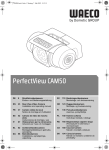
1
_CAM50.book Seite 1 Montag, 7. Mai 2012 3:12 15 PerfectView CAM50 DE 8 Rückfahrvideokamera Einbau- und Bedienungsanleitung SV 110 Backningsvideokamera Monterings- och bruksanvisning EN 23 Rear View Video Camera Installation and operating manual NO 123 Ryggevideokamera Montasje- og bruksanvisning FR 37 Caméra vidéo de recul Notice de montage et d’utilisation FI 136 Peruutusvideokamera Asennus- ja käyttöohje ES 52 PL 150 Kamera cofania Instrukcja montażu i obsługi IT 67 Cámara de vídeo de marcha atrás Instrucciones de montaje y uso Videocamera per la retromarcia Istruzioni per I’uso e il montaggio RU NL 82 CS DA 96 Achteruitrijvideocamera Montagehandleiding en gebruiksaanwijzing Bakvideokamera Installations- og betjeningsvejledning 165 Видеокамера заднего вида Инструкция по монтажу и эксплуатации 180 Couvací kamera Návod k montáži a obsluze SK 194 Cúvacia kamera Návod na montáž a uvedenie do prevádzky _CAM50.book Seite 2 Montag, 7. Mai 2012 3:12 15 PerfectView CAM50 1 1 4 2 3 5 7 10 2 6 8 9 11 12 _CAM50.book Seite 3 Montag, 7. Mai 2012 3:12 15 PerfectView CAM50 2 3 4 5 6 7 3 _CAM50.book Seite 4 Montag, 7. Mai 2012 3:12 15 PerfectView CAM50 8 1 2 3 5 4 9 3 1 2 4 6 _CAM50.book Seite 5 Montag, 7. Mai 2012 3:12 15 PerfectView CAM50 0 a 90° b c d e 5 _CAM50.book Seite 6 Montag, 7. Mai 2012 3:12 15 PerfectView CAM50 f g ~50 ° h A i B j A B 6 _CAM50.book Seite 7 Montag, 7. Mai 2012 3:12 15 PerfectView CAM50 k 7 _CAM50.book Seite 23 Montag, 7. Mai 2012 3:12 15 PerfectView CAM50 Please read this instruction manual carefully before installation and first use, and store it in a safe place. If you pass on the product to another person, hand over this instruction manual along with it. Contents 1 Explanation of symbols . . . . . . . . . . . . . . . . . . . . . . . . . . . . . . . . . . 24 2 Safety and installation instructions. . . . . . . . . . . . . . . . . . . . . . . . . . 24 3 Scope of delivery . . . . . . . . . . . . . . . . . . . . . . . . . . . . . . . . . . . . . . . 27 4 Accessories . . . . . . . . . . . . . . . . . . . . . . . . . . . . . . . . . . . . . . . . . . . 27 5 Intended use . . . . . . . . . . . . . . . . . . . . . . . . . . . . . . . . . . . . . . . . . . 27 6 Technical description . . . . . . . . . . . . . . . . . . . . . . . . . . . . . . . . . . . . 28 7 Notes on the electrical connections . . . . . . . . . . . . . . . . . . . . . . . . . 28 8 Mounting the camera . . . . . . . . . . . . . . . . . . . . . . . . . . . . . . . . . . . . 30 9 Cleaning and caring for the camera. . . . . . . . . . . . . . . . . . . . . . . . . 34 10 Guarantee . . . . . . . . . . . . . . . . . . . . . . . . . . . . . . . . . . . . . . . . . . . . 34 11 Disposal . . . . . . . . . . . . . . . . . . . . . . . . . . . . . . . . . . . . . . . . . . . . . . 35 12 Technical data . . . . . . . . . . . . . . . . . . . . . . . . . . . . . . . . . . . . . . . . . 35 EN 23 _CAM50.book Seite 24 Montag, 7. Mai 2012 3:12 15 Explanation of symbols PerfectView CAM50 1 Explanation of symbols ! ! A I WARNING! Safety instruction: Failure to observe this instruction can cause fatal or serious injury. CAUTION! Safety instruction: Failure to observe this instruction can lead to injury. NOTICE! Failure to observe this instruction can cause material damage and impair the function of the product. NOTE Supplementary information for operating the product. ➤ Action: This symbol indicates that action is required on your part. The required action is described step-by-step. ✓ This symbol describes the result of an action. fig. 1 5, page 3: This refers to an element in an illustration. In this case, item 5 in figure 1 on page 3. 2 Safety and installation instructions Please observe the prescribed safety instructions and stipulations from the vehicle manufacturer and service workshops. The manufacturer accepts no liability for damage in the following cases: Faulty assembly or connection Damage to the product resulting from mechanical influences and excess voltage Alterations to the product without express permission from the manufacturer Use for purposes other than those described in the operating manual 24 EN _CAM50.book Seite 25 Montag, 7. Mai 2012 3:12 15 PerfectView CAM50 Safety and installation instructions Please observe the following instructions: To prevent short circuits, always disconnect the negative terminal of the vehicle’s electrical system before working on it. If the vehicle has an additional battery, its negative terminal should also be disconnected. Insufficient supply line connections could result in short circuits which – Cause cable fires – Trigger the airbags – Damage electronic control devices – Cause electric functions to fail (indicators, brake light, horn, ignition, lights) When working on the following lines, only use insulated cable lugs, plugs and tab sleeves: – 30 (direct supply from positive battery terminal) – 15 (connected positive terminal, behind the battery) – 31 (return line from the battery, earth) – 58 (reversing light) Do not use porcelain wire connectors. Use a crimping tool (fig. 1 10, page 2) to connect the cables. When connecting to supply line 31 (earth), screw the cable – To the vehicle’s earth bolt with a cable lug and a gear disc or – To the sheet metal body work with a cable lug and a self-tapping screw. Ensure that there is a good earth connection. When the negative terminal of the battery is disconnected, all data stored in the volatile memories will be lost. The following data must be set again, depending on the vehicle equipment options: – Radio code – Vehicle clock – Timer – On-board computer – Seat position You can find instructions for making these settings in the appropriate operating instructions. EN 25 _CAM50.book Seite 26 Montag, 7. Mai 2012 3:12 15 Safety and installation instructions PerfectView CAM50 Observe the following installation instructions: Secure the parts of the camera installed in the vehicle in such a way that they cannot become loose under any circumstances (sudden braking, accidents) and cause injuries to the occupants of the vehicle. Secure any parts of the system covered by the bodywork in such a manner that they cannot be come loose or damage other parts and cables and impair vehicle functions (steering, pedals, etc.). To prevent damage, when drilling ensure that there is sufficient room for the drill head to come out on the other side (fig. 2, page 3). Deburr all drill holes and treat them with a rust-protection agent. Always follow the safety instructions of the vehicle manufacturer. Some work (e.g. on retention systems such as the AIRBAG etc.) may only be performed by qualified specialists. Observe the following instructions when working with electrical parts: When testing the voltage in electrical cables, only use a diode test lamp (fig. 1 8, page 2) or a voltmeter (fig. 1 9, page 2). Test lamps with an illuminant (fig. 1 12, page 2) take up voltages which are too high and which can damage the vehicle’s electronic system. When making electrical connections, ensure that – They are not kinked or twisted – They do not rub on edges – They are not laid in sharp edged ducts without protection (see fig. 3, page 3) Insulate all connections. Secure the cables against mechanical wear with cable binders or insulating tape, for example to existing cables. The camera is watertight. However, the sealings on the camera cannot withstand a high-pressure cleaner (fig. 4, page 3). Therefore, you should observe the following instructions when handling the camera: People (including children) whose physical, sensory or mental capacities or whose lack of experience or knowledge prevent them from using this product safely should not use it without the supervision or instruction of a responsible person. Do not open the camera, as this impairs the sealing and the function of the camera (fig. 5, page 3). 26 EN _CAM50.book Seite 27 Montag, 7. Mai 2012 3:12 15 Scope of delivery PerfectView CAM50 Do not pull at the cables, as this impairs the sealing and the function of the camera (fig. 6, page 3). The camera is not suitable for submerged operation (fig. 7, page 3). 3 Scope of delivery No. in fig. 8, page 4 Quantity 1 4 Description Item number 1 Monochrome camera CAM50 Colour camera CAM50C 9102000028 9102000019 2 1 Camera bracket 9102200066 3 1 Camera guard 9102200067 4 2 Side covers 5 1 Extension cable – 1 Fastening material 9102200030 Accessories Available as accessory (not included in scope of delivery): Description Item number Extension cable 5 m RV-805 91022000028 Extension cable 8 m RV-810 91022000029 Extension cable 20 m RV-820 91022000030 Spiral cable for trailer operation RV-150-SPK 91022000031 5 Intended use The CAM50 monochrome camera (item no. 9102000028) and the CAM50C colour camera (item no. 9102000019) are primarily intended for use in vehicles. They can be used in rear view video systems to observe the space directly beside or behind the vehicle from the driver’s seat when manoeuvring or parking, for example. EN 27 _CAM50.book Seite 28 Montag, 7. Mai 2012 3:12 15 Technical description PerfectView CAM50 ! WARNING! Risk of injury! Since rear view systems are designed merely as an additional aid for reversing, it does not relieve you of the duty to take proper care when reversing. 6 Technical description The camera with integrated microphone, which is encased in aluminium housing, transmits image and sound to a monitor via a cable. The built-in infrared LEDs improve night vision. The camera transmits the image as if you are looking in the rear mirror. The camera consists of the following main elements: No. in Description fig. 9, page 4 1 6-pin connection cable 2 Infrared LEDs 3 Microphone (back side) 7 Notes on the electrical connections 7.1 Laying cables A NOTICE! Risk of damage! To prevent damage, when drilling ensure that there is sufficient space on the other side for the drill head to come out. Cables and connections which are not properly installed will cause malfunctions or damage to components. Correct installation of cables and connections is the basic prerequisite for lasting and trouble-free operation of the retrofitted components. The cables may not be exposed for long periods to solvents such as benzine, as the solvents can damage the cable. 28 EN _CAM50.book Seite 29 Montag, 7. Mai 2012 3:12 15 PerfectView CAM50 Notes on the electrical connections Please observe the following instructions: As far as possible, use original openings or alternative openings for the connecting cable duct, e.g. the paneling edges, ventilation grilles or blank panels. If no openings are available, you must drill holes for the cables. Check beforehand that there is sufficient room for the drill head to come out on the other side. Wherever possible lay cables inside the vehicle, as they are better protected inside than outside the vehicle. If you do need to lay a cable outside the vehicle, ensure that it is well secured (use additional cable ties, insulating tape, etc.). To prevent damage to the cables, when laying them ensure that there is sufficient distance to hot or moving vehicle components (exhaust pipes, drive shafts, light systems, fans, heater etc.). Use corrugated piping or other protective materials to protect against mechanical wear. Screw on the plug connections of the connecting cables to protect against water penetration (fig. h, page 6). When laying electric connections, ensure that – They are not kinked or twisted – They do not rub on edges – They are not laid in sharp edged ducts without protection (fig. 3, page 3) Attach the cables securely in the vehicles to prevent tripping hazards. Use cable binders, insulating tape or glue the cables in place. Protect every through-hole made in the bodywork against water penetration, e.g. by using a cable with a sealant and by spraying the cable and the the cable sleeve with sealant. I EN NOTE Do not start sealing the through-holes until all installation work has been finished for the camera, and the required cable lengths have been established. 29 _CAM50.book Seite 30 Montag, 7. Mai 2012 3:12 15 Mounting the camera 8 Mounting the camera 8.1 Tools required PerfectView CAM50 For installation and assembly you will require the following tools: Drill bit set (fig. 1 1, page 2) Drill (fig. 1 2, page 2) Screwdriver (fig. 1 3, page 2) Set of ring or open-ended spanners (fig. 1 4, page 2) Measuring ruler (fig. 1 5, page 2) Hammer (fig. 1 6, page 2) Centre punch (fig. 1 7, page 2) To make and test the electrical connection, the following tools are required: Diode test lamp (fig. 1 8, page 2) or voltmeter (fig. 1 9, page 2) Insulating tape (fig. 1 11, page 2) Cable bushing sleeves, if necessary To fasten the cables you may require additional cable binders. 8.2 Mounting the camera ! CAUTION! Select a location for the camera and attach it so securely that it cannot under any circumstances fall off and injure bystanders (e.g. by being knocked off by branches brushing over the roof of the vehicle). I NOTE If installing the camera alters the vehicle height or length specified in the vehicle documents, your vehicle must be inspected by the appropriate authorities. Make sure that you are in possession of documents verifying that your vehicle has passed this inspection. 30 EN _CAM50.book Seite 31 Montag, 7. Mai 2012 3:12 15 PerfectView CAM50 Mounting the camera Observe the following installation instructions: To provide a suitable viewing angle, the camera must be attached at a height of at least 2 m. Ensure that you have a firm place from which to work when mounting the camera. Ensure that the installation location of the camera is sufficiently firm (e.g. to prevent the camera from being knocked down by branches that may brush over the roof of the vehicle). Mount the camera bracket horizontally and in the middle of the rear of the vehicle (fig. 0, page 5). The most secure type of attachment is with screws fitted through the body. Please observe the following instructions: – There must be sufficient space for the mounting procedure behind the chosen installation location. – Suitable measures must be taken to prevent water penetrating through any holes made (e.g. by using screws and sealant and/or spraying the outer attachment parts with a sealant). – The location on the body where you wish to attach the camera must be rigid enough to allow the camera to be tightly fastened. Check beforehand that there is sufficient room for the drill head to come out on the other side (fig. 2, page 3). If you are not sure about the location you have chosen, consult the vehicle manufacturer or dealer. I NOTE We recommend greasing the threads of the bolts to prevent corrosion. When mounting the camera, proceed as follows: ➤ Hold the camera on the chosen location and mark at least two different points for the drill holes (fig. a, page 5). ➤ Using a hammer and centre punch, gently pre-punch the previously marked points to prevent the drill head from slipping off. EN 31 _CAM50.book Seite 32 Montag, 7. Mai 2012 3:12 15 Mounting the camera PerfectView CAM50 If you want to screw on the camera with self-tapping screws (fig. b, page 5) A NOTICE! Risk of damage! The holder may only be attached to steel panels with a minimum thickness of 1.5 mm using self-tapping screws. ➤ Drill Ø 2 mm holes at the points you have just marked. ➤ Deburr all drill holes and apply rust-protection. ➤ Screw the camera bracket on with the 3 x 10 mm self-tapping screws. If you would like to attach the camera with threaded screws fitted through the construction (fig. c, page 5) A NOTICE! Risk of damage! Ensure that that nuts cannot be pulled through the body shell when they are tightened. Use larger washers or metal plates if necessary. ➤ Drill Ø 3.5 mm holes at the points you have just marked. ➤ Deburr all drill holes and apply rust-protection. ➤ Screw the camera bracket on with the M3 x 20 mm threaded screws. Depending on the thickness of the construction, you may require longer threaded screws. Creating a through-hole for the camera connection cable (fig. d, page 5) I NOTE If possible, use available openings – such as ventilation grilles – to feed the connection cables through. If there are no existing openings, you must drill a hole with a 16 mm diameter. A NOTICE! Risk of damage! Ensure that there is sufficient space on the other side for the drill head to come out 32 EN _CAM50.book Seite 33 Montag, 7. Mai 2012 3:12 15 PerfectView CAM50 Mounting the camera ➤ Drill a hole of Ø 16 mm near the camera. ➤ Deburr all drill holes that have been made in the sheet metal and apply rust-protection. ➤ Place cable sleeves in all sharp edged ducts. Mounting the camera A NOTICE! Risk of damage! Only use the screws supplied to mount the camera in the camera bracket. Longer screws will damage the camera. ➤ Push the camera into the camera bracket. ➤ Attach the camera loosely with the two screws M3 x 6 mm in the slots (fig. e, page 5). ➤ Align the camera provisorily so that the lens is at an angle of approx. 50° to the perpendicular axis of the vehicle (fig. f, page 6). A NOTICE! Risk of damage! Never mount the camera without the camera guard. ➤ Push the camera guard over the camera (fig. g, page 6) Connecting the camera I NOTE Lay the camera cable so that should you need to remove the camera, you can access the plug connection between the camera and the extension cable easily. This considerably eases dismantling work. To minimise corrosion in the plug, apply a small amount of grease – such as pin grease – inside the plug. Additional extension cables are available on request (see “Accessories” on page 27). ➤ Guide the camera cable into the vehicle interior. ➤ Insert the plug of the camera cable into the socket of the extension cable. ➤ Screw on the plug connections of the connecting cables to protect against water penetration (fig. h, page 6). EN 33 _CAM50.book Seite 34 Montag, 7. Mai 2012 3:12 15 Cleaning and caring for the camera PerfectView CAM50 Aligning the camera I NOTE If necessary before aligning the camera connect the camera to a monitor and to a power supply (see connecting diagram, fig. i, page 6 ➤ Use the monitor image to align the camera: The monitor image should show the bottom edge of the rear or the bumper of your vehicle (A). The middle of the bumper should be in the middle of the screen. (fig. j, page 6). ➤ Check the function of the camera after you have connected it to a monitor. Fastening the camera ➤ Thighten the two screws in the slots of the camera bracket. ➤ Mount the side covers with the two screws M3 x 8 mm in the middle drill holes (fig. k, page 7). 9 Cleaning and caring for the camera A NOTICE! Risk of damage! Do not use sharp or hard objects to clean the device as these may damage the device. ➤ Clean the camera with a soft, damp cloth from time to time. 10 Guarantee The statutory warranty period applies. If the product is defective, please contact the manufacturer's branch in your country (see the back of the instruction manual for the addresses) or your retailer. For repair and guarantee processing, please send the following items: Defect components A copy of the receipt with purchasing date A reason for the claim or description of the fault 34 EN _CAM50.book Seite 35 Montag, 7. Mai 2012 3:12 15 Disposal PerfectView CAM50 11 Disposal ➤ Place the packaging material in the appropriate recycling waste bins wherever possible. M If you wish to finally dispose of the product, ask your local recycling centre or specialist dealer for details about how to do this in accordance with the applicable disposal regulations. 12 Technical data Item no: Image sensor: Pixels: PerfectView CAM50 PerfectView CAM50C 9102000028 9102000019 1/4" CCD approx. 270000 pixels Video standard: PAL, 1 Vpp Light sensitivity: < 1 Lux / 0 Lux with infrared LEDs Picture angle: Operating voltage: Power consumption: Operating temperature: Protection class: Resistance against vibration: Dimensions W x H x D (with camera bracket): Weight: approx. 120° diagonal approx. 100° horizontal approx. 70° vertical 11 – 16 Vg 1.8 W –20 °C to +65 °C IP68 6g 94 x 62 x 48 mm approx. 0.4 kg Versions, technical modifications and delivery options reserved. EN 35 _CAM50.book Seite 36 Montag, 7. Mai 2012 3:12 15 Technical data PerfectView CAM50 Approval The device has the E11 approval. E 36 EN _CAM50.book Seite 208 Montag, 7. Mai 2012 3:12 15 k Dometic WAECO International GmbH Hollefeldstraße 63 · D-48282 Emsdetten +49 (0) 2572 879-195 · +49 (0) 2572 879-322 Mail: [email protected] · Internet: www.dometic-waeco.de Overseas + Middle East a Dometic Austria GmbH Neudorferstrasse 108 2353 Guntramsdorf +43 2236 908070 +43 2236 90807060 Mail: [email protected] L Dometic Norway AS Skolmar 24 N-3232 Sandefjord +47 33428450 +47 33428459 Mail: [email protected] 8 Dometic Australia 1 John Duncan Court Varsity Lakes QLD 4227 +61 7 55076000 +61 7 55076001 Mail: [email protected] h Dometic Switzerland AG Riedackerstrasse 7a CH-8153 Rümlang (Zürich) +41 44 8187171 +41 44 8187191 Mail: [email protected] N Dometic Benelux B.V. Ecustraat 3 NL-4879 NP Etten-Leur +31 76 5029000 +31 76 5029090 Mail: [email protected] 5 l Dometic Denmark A/S Nordensvej 15, Taulov DK-7000 Fredericia +45 75585966 +45 75586307 Mail: [email protected] P Dometic Poland Sp. z o.o. Ul. Puławska 435A 02-801 Warszawa Poland +48 22 414 32 00 +48 22 414 32 01 Mail: [email protected] WAECO Impex Ltd. Suites 2207-2211 · 22/F · Tower 1 The Gateway · 25 Canton Road, Tsim Sha Tsui · Kowloon Hong Kong +852 24611386 +852 24665553 Mail: [email protected] 7 WAECO Impex Ltd. Taipei Office 2 FL-3 · No. 56 Tunhua South Rd, Sec 2 Taipei 106, Taiwan +886 2 27014090 +886 2 27060119 Mail: [email protected] 6 Dometic AB Regional Office Middle East P O Box 74775 Dubai, United Arab Emirates +971 4 321 2160 +971 4 321 2170 Mail: [email protected] 0 Dometic Marine Division 2000 N. Andrews Ave. Extension Pompano Beach, FL 33069 USA +1 954 973 2477 +1 954 979 4414 Mail: [email protected] m p Dometic Spain S.L. Avda. Sierra del Guadarrama, 16 E-28691 Villanueva de la Cañada Madrid +34 902 111 042 +34 900 100 245 Mail: [email protected] Dometic S.N.C. ZA du Pré de la Dame Jeanne F-60128 Plailly +33 3 44633500 +33 3 44633518 Mail: [email protected] q Dometic Finland OY Mestarintie 4 FIN-01730 Vantaa +358 20 7413220 +358 9 7593700 Mail: [email protected] C Dometic Italy S.p.A. Via Virgilio, 3 I-47100 Forlì +39 0543 754901 +39 0543 756631 Mail: [email protected] T U Dometic RUS LLC Komsomolskaya square 6-1 107140 Moscow Russia +7 495 780 79 39 +7 495 916 56 53 Mail: [email protected] Dometic Scandinavia AB Gustaf Melins gata 7 S-42131 Västra Frölunda (Göteborg) +46 31 7341100 +46 31 7341101 Mail: [email protected] W Dometic Slovakia s.r.o. Tehelná 8 SK-98601 Fiľakovo +421 47 4319 107 +421 47 4319 166 Mail: [email protected] 4 Dometic UK Ltd. Dometic House · The Brewery Blandford St. Mary Dorset DT11 9LS +44 844 626 0133 +44 844 626 0143 Mail: [email protected] www.dometic-waeco.com 3.03.19.01732 05/2012 Europe