1
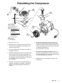
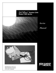
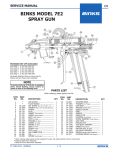
INSTRUCTIONS–PARTS LIST
308–185
Rev. F
This manual contains important
warnings and information.
READ AND RETAIN FOR REFERENCE
Supercedes Rev. E
110/230V, 15/7.5A, ONE CYLINDER, COMPACT OIL–LESS
Compressor
GRACO Part No. 236–526, Series A
DeVILBISS Part No. CAC–4093
WARNING
WARNING
EQUIPMENT MISUSE HAZARD
Equipment misuse can cause the equipment to rupture or malfunction and result in serious injury.
INSTRUCTIONS
This equipment is for professional use only.
Read all instruction manuals, tags, and labels before operating the equipment.
Use the equipment only for its intended purpose. If you are not sure, call Graco Technical Assistance at 1–800–543–0339.
Do not expose the system to rain. Always store the system indoors.
Do not alter or modify this equipment.
Check equipment daily. Repair or replace worn or damaged parts immediately.
Do not exceed the maximum working pressure of the lowest rated component in your system.
This equipment has a 100 psi (7 bar) maximum working pressure at 100 psi (7 bar) maximum incoming air pressure.
The system is for use only with water-based simulated acoustic and wall texture materials. Use fluids and solvents compatible with the equipment wetted parts. Refer to the Technical
Data section of all equipment manuals. Read the fluid and solvent manufacturer’s warnings.
Never directly inhale compressed air. Compressed air may contain toxic vapors.
Wear appropriate clothing, eye protection, and breathing apparatus for the material sprayed.
To reduce the risk of serious injury, including electric shock and splashing fluid in the eyes, follow
the Pressure Relief Procedure on page 2 before checking or repairing the compressor.
FIRE AND EXPLOSION HAZARD
Improper grounding, poor ventilation, open flames or sparks can cause a hazardous condition and
result in a fire or explosion and serious injury.
Locate the sprayer at least 20 ft (6.1 m) away from any explosive vapors, due to arcing parts.
Use a time delay fuse or circuit breaker protected electrical circuit of the specified voltage and
amperage. In the U.S. and Canada, the fuse must be marked with a T.
Comply with all applicable local, state, and national fire, electrical, and safety regulations.
GRACO INC.
P.O. BOX 1441 MINNEAPOLIS, MN
COPYRIGHT 1991, GRACO INC.
55440–1441
General Information
Air intake filter replacement
WARNING
To reduce the risk of serious injury, including electric shock and splashing fluid in the eyes, follow the
Pressure Relief Procedure before checking or
repairing the compressor.
Pressure Relief Procedure
1. Shut off the sprayer.
Remove and wash both air intake filters every time you
flush the system. A dirty filter will not allow the compressor to operate at full capacity. Replace the filters if
they are worn.
Never operate the sprayer with the filters removed.
Motor thermal overload protector
The motor has an automatic reset thermal overload
protector. If the motor overheats, the overload protector will shut it off.
2. Trigger the gun.
3. Open the gun air valve.
4. Unplug the sprayer.
WARNING
Extension cords
Try to use longer air and fluid hoses–up to 100 ft.(15
m) maximum–rather than an extension cord. If an extension cord is used, use a maximum 50 ft (15 m) cord
with 3 wires of 12, 10 or 8 gauge (AWG) and a
3–prong grounding plug. Plug into a properly
grounded, 3–prong outlet. Do not use an adapter and
do not use 14 or 16 AWG cords.
To reduce the risk of serious injury due to the
sprayer restarting unexpectedly, always manually
turn off the sprayer if the motor shuts down.
If the overload protector shuts the motor off frequently,
check for a voltage problem. Check for low voltage if
any of the following conditions exist.
1. Motor does not get up to full power or speed.
Lubrication
2. Fuses blow out when starting the motor.
This compressor needs no lubrication or oiling.
3. Lights dim and remain dim when the motor is
started and running.
Troubleshooting
PROBLEM
CAUSE
SOLUTION
Air leaks
Hose fitting is loose
Tighten fitting.
Restricted air intake filters
Clean or replace the filters.
Hole in air and/or fluid hoses
Replace the damaged hose.
Air leaks
Tighten all fittings.
Restricted air intake
Dirty air intake filters
Clean or replace filters. Place sprayer outside spray area.
Motor will not run
Motor thermal overload
protector has tripped
SHUT OFF SPRAYER. Allow motor to cool, then restart sprayer. If
protector trips often, check for low voltage problem.
Fuse blow or circuit breaker
tripped
1. Check and/or replace fuse, or reset circuit breaker. Do not use
a fuse or circuit breaker with a higher rating than that specified
for your particular branch circuit.
2. Check for proper fuse. Use only a Time Delay fuse marked T.
3. Check extension cord. See description below.
4. Disconnect other appliances from the circuit or operate the
sprayer on its own branch circuit.
Extension cord is wrong
length or gauge
See Extension cords, above.
Loose electrical connections
Check wiring connection inside terminal box area.
Faulty motor
Have checked at a local service center. Call 1–800–888–2468 for
nearest location.
Rebuilding the Compressor
2
4
B
3
10
22
A
C
7
8
9
Torque to
30–45 in-lb
(3.4–5 N.m)
Torque to 75–90 in-lb
(8.5–10 N.m)
For Series B compressor:
Use button head
capscrew and torque to
75–90 in-lb
(8.5–10 N.m)
For Series A compressor:
use hex screw and
torque to 30–35 in-lb
(3.4–3.9 N.m)
12,13
14
16
Using cross pattern,
torque to
84–120 in-lb
(9.5–13.5 N.m)
1. Remove the fan (14).
2. Disassemble the compressor head (3) as shown.
To remove the connecting rod and cylinder (10),
loosen its setscrew (B).
3. If you are using the old valve plate (8), scrape the
old gasket (7) off of it.
4. Install the cylinder sleeve with its notch (A) toward
the rear of the motor. Lower the connecting rod
(10) into place so its part number faces out. Position the piston around the bearing (12) and tighten
the connecting rod to 120–140 in-lb
(13.5–16 N.m).
6. Install the remaining parts, except the fan (14).
Be sure the longer head screws (4) are installed
toward the rear of the motor. Always using a cross
pattern, hand tighten the screws (2,4), torque lightly, and then torque again to
84–120 in-lb (9.5–13.5 N.m).
7. Be sure the compressor operates. Hold on to
the motor firmly and plug it in to ensure there is air
from the discharge. If not, check the position of the
valve plate (8) discharge valves (C).
8. Install the fan (14), matching the keyway to the
bearing (12).
5. Place the o–ring (9) in the valve plate (8) groove.
Install the valve plate, o–ring down, with the discharge valves (B) facing right as shown in the
drawing.
Parts
1*
2
4
5
6
3
22*
10*
20
7
19
8
11
9
Torque to
30–45 in-lb
(3.4–5 N.m)
14
For Series B compressor:
Use button head capscrew
and torque to
75–9
0 in-lb
(8.5–10 N.m)
18
17
For Series A compressor:
use hex screw and
torque to 30–35 in-lb
(3.4–3.9 N.m)
12,13
Using cross pattern,
torque to
84–120 in–lb
(9.5–13.5 N.m)
Manual
Change Summary
21
Ref DeVILBISS
No. Part No.
GRACO
Part No.
1*
2
3
4
5
6
7
8
9
10*
11
12
13
14
CAC–1173–1
SSF–990
ACG–26
SSF–6640
SSP–7821
CAC–1120
ACG–45
ACG–402
SSG–8156
KK–4835
C–MO–3020–1–B
CAC–4306
SSF–2043
CAC–1148–1
111–601
15
16
17
18
19
20
21
22*
SS–6509–CD
SSF–3101
CAC–1098
CAC–1099
CAC–1415
SSF–993
KK–5040
15
16
111–572
111–573
113–384
111–604
224–795
224–986
Series B
111–591
111–584
111–585
111–583
112–403
111–593
235–959
238–164
Description
INTAKE MUFFLER
SCREW, 1/4–20 X 1–1/4
HEAD
STUD, 1/4–20 x 1–1/4
COMPRESSION NUT
SLEEVE
O-RING
VALVE PLATE ASSY.
O–RING
CONNECTING ROD ASSY.
3.5 HP MOTOR
ECCENTRIC FLYWHEEL
SETSCREW
SQUIRREL CAGE FAN KIT
Includes items 16
WASHER
SCREW, #10–24 X 3/8”
COMPRESSOR VIBRATION PAD
MOTOR VIBRATION PAD
COVER PLATE
GROUNDING SCREW
BLOWER DUCT
VALVE PLATE ASSEMBLY KIT
Qty
1
2
1
2
1
1
1
1
1
1
1
1
1
1
1
1
2
1
1
1
1
1
Within Compressor Rebuild Kit
224–989, Head Gasket Kit
224–797 has been replaced by
Valve Plate Assembly Kit
238–164.
Also, CAC–112–403–U–1,
CAC–1175, and CAC–4281–1
were replaced by ACG–26,
ACG–45 and ACG–402, respectively.
DeVilbiss Warranty
This air compressor is warranted against failure due to
defects in material or workmanship for a period of one
year from the date of purchase
of the sprayer.
*INCLUDED IN GRACO REBUILD KIT 224–989
INCLUDED IN GRACO REPAIR KIT 238–164
DeVILBISS AIR POWER COMPANY, 213 Industrial Drive, Jackson, TN 38301–9615
4
308-185
PRINTED IN U.S.A. Graco Manual No. 308–185 10/91 Revised October 1995