1
Installation and Operating Instructions
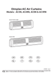
Dimplex Air Curtains
Models : AC3N, AC45N, AC6N & AC3RN
08/18848/0
Issue 0
’C’
Dimensions
ceiling
(millimetres)
Hole
centres
50
’B’
Watt
A
B
C
AC3N
3.0kw
605
424
492
AC45N
4.5kw
605
424
492
AC6N
6.0kw
905
721
756
AC3RN
3.0kw
605
424
492
(Remote control)
wall mtd.
45
Bracket
length
Model(s)
ceiling mtd.
214
200
cable/conduit
entry
’A’
135
Front view
155
Side views
Fig. 1
THESE INSTRUCTIONS SHOULD BE READ CAREFULLY AND RETAINED FOR FUTURE REFERENCE.
IMPORTANT SAFETY ADVICE
DO NOT COVER OR OBSTRUCT the air inlet or outlet
grille.
ENSURE THE APPLIANCE IS EARTHED.
Do not use this heater in areas where excessive dust
exists.
This heater must not be located immediately above
or below a fixed socket outlet or connection box.
Always disconnect supply before working on the
product.
This product should be mounted safely to solid wall
or ceiling surfaces only.
Ensure the supply cables are of adequate current carrying capacity and are protected by a suitable fuse.
If the appliance is mounted in a toilet or washroom,
the appliance should be mounted such that no part
of it can be touched by a person using a fixed bath or
shower.
Installation
Using the wall mounting bracket as a guide (see Fig. 3) mark
off the hole positions on the wall or ceiling - a minimum height
of 1.8metres is required from floor to bracket. Fix the bracket
in position by following steps as described under the heading
‘Wall or Ceiling Mounting’.
Wall or Ceiling Mounting
Solid brick or concrete block walls must be drilled and plugged
(using a spirit level as a guide ensure bracket is level) with
rawlplug No. 8 size fibre inserts. The plug must be located in
the solid part of the wall, not just in the plaster layer.
For panelled internal walls or ceilings, it is best to locate the
studding, position the heater fixing bracket accordingly and
use No. 8 size wood screws. If it is not possible to locate the
studding, use type M4 Rawlplug inserts, making the 10mm
holes with a drill rather than a bradawl or a screwdriver.
If the appliance is mounted in a toilet or washroom
an isolating switch must be provided outside the
washroom adjacent to the entrance door.
Electrical
The installation of this appliance should be carried out by a
competent electrician and be in accordance with the current
IEE wiring regulations.
Fixing Positions
This appliance may be either wall-mounted or fixed to a ceiling - see Fig. 2 for various fixing positions and ‘Installation’ for
details on fixing.
wall
mounting
bracket
see Fig. 4
Locate the heater
on the mounting
bracket ensuring
that the pozi-head
screws are fully engaged in the slots
of the bracket.
Fig. 3
It is important that the serrated metal washer is located between the heater holding bracket and the wall mounting
bracket. Adjust heater to the required angle then firmly tighten
the fixing screws inside the endcap using a cross-head screwdriver as shown in Fig. 4.
wall
mounting
bracket
Ceiling mounting
access hole for
screwdriver
serrated washer
holding bracket
fixing screw
Wall mounting
Fig. 2
Heaters may be mounted end to end for wide doorways.
Detail view of Wall fixing bracket arrangement
Fig. 4
Release the screws at either end of the air-outlet grille (see
Fig. 5) to gain access to the terminals for connection of the
supply cable - see Fig. 6.
M
Element
Element
CUT-OUT
see Fig. 6
screw
outlet
grille
CUT-OUT
Heat
Switches
Isolater
Switch
screw
Terminal
Block
Fig. 5
Cable
clamp
Mains
Cable
Insert the mains cable down
the outside of the back panel
(not on inside) and through
the rear entry cable clamp
and make connection as
shown in Fig. 6 see also Fig.
7 for detailed views of cable
clamps.
Fig. 6Detail view of cable entry
L
N
E
M
Element
Element
CUT-OUT
CUT-OUT
Heat
Switches
Isolator
Switch
cable
’A’
Fig. 8
AC3N
Wiring
Diagram
E
Fig. 7a
Cable clamp detail for
AC3N & AC3RN models
Fig. 9
AC45N
Wiring
Diagram
E
Terminal
Block
L N E
’B’
cable
’A’
’B’
Fig. 7b
Cable clamp detail for
AC45N & AC6N models
Note : Part ‘A’ of cable
clamp is flipped over to
receive the larger cable
Connection to fixed wiring should be made through an adjacent minimum 20 amp double-pole switch for AC3N, AC3RN
& AC45N models.
Element
Element
M
CUT-OUT
CUT-OUT
Heat
Switches
Isolator
Switch
E
Terminal
Block
Connection to fixed wiring should be made through an adjacent minimum 30 amp double-pole switch for AC6N model
with a minimum separation of 3mm in each pole.
L
N
Fig. 10
AC6N
Wiring
Diagram
E
E
Re-secure the outlet grille.
Ensure that the air-curtain is securely fastened and that the
supply cable is firmly clamped before operating the appliance.
M
Element
Element
CUT-OUT
CUT-OUT
N
L
OUT
IN
Heat
Switches
Isolator
Switch
E
Terminal
Block
L N E
Fig. 11
AC3RN
Wiring
Diagram
Operation (AC3N, AC45N & AC6N models)
Remote Control (AC3RN model only)
Switch on electricity supply
to the heater.
Insert the 9 volt battery into the remote control.
Press either the ON or OFF button to check the operation of
the remote. The green light on the front of the remote control
will light.
Switch the heater to AUTO for automatic operation.
Press the ON button to activate the heater, and OFF to turn
off.
If the remote control does not operate the heater, first check
battery and then follow the instructions under ‘Resetting
AC3RN remote control’ below.
Switching the switch
marked ‘ I ’ energises the
blower.
Select ‘ I ‘ and the smaller
switches marked ‘ z ’ as required (see Fig. 12).
Settings -
Fig. 12
I
: Blower only
I+z
: Half heat
I+z +z
: Full heat
Operation (AC3RN model)
Switch on electricity supply
to the heater.
Select the switch position ‘
MAN ’ for Manual Operation.
AUTO
MAN
Select the switch position ‘
AUTO ’ for Operation via
the remote control.
reset
button (AC3RN only)
Fig. 13
Select the desired heat output using the smaller switches
position ‘z’ (see Fig. 13).
To operate the remote control you must first select ‘AUTO’ .
The heater may now be turned ‘On’ or ‘Off’ using the Remote
Control.
Settings -
MAN
: Blower only
AUTO
: Remote On/Off
MAN + z
: Half heat
MAN + z + z
: Full heat
‘AUTO’ will default to ‘OFF’ if the remote control is not being
used.
The range of the Remote Control is 15 metres.
Note :
Repeated simultaneous switching of the ‘ON’ and ‘OFF’ buttons on the remote control may require resetting of the heatersee ‘Resetting AC3RN remote control’.
If the remote control becomes lost, switch off at the mains
supply for at least 30 seconds and select ‘MAN’ for Manual
Operation.
Resetting AC3RN remote
control
Switch the heater to automatic operation, and ensure
the remote control is functioning. (green light should
operate)
Insert a small non-metallic
pin (dia. less than 2mm e.g.
a toothpick or match) into the
hole shown in Fig. 14 and
press the reset button. At the
same time press the ON button on the remote control.
Release the reset button on
the heater and the button on
the remote control at the
same time.
The heater is now programmed to operate with
this remote sender unit.
Note this method can be
used to program a number
of heaters to operate from a
single remote control.
Fig. 14
green
neon light
ON button
OFF button
wall
mounted
holster
Fig. 15
The remote control may be placed
when not in use in the wallmounted holster provided (see
Fig. 15).
Screws and rawl plugs for wall fixing the holster are provided
also.
Important Battery information.
Discard leaky batteries.
Dispose of batteries in the proper manner according to
Provincial and local regulations. Any battery may leak
electrolyte if mixed with a different battery type, if inserted
incorrectly, if all the batteries are not replaced at the same
time, if disposed of in a fire or if an attempt is made to
charge a battery not intended to be recharged.
Maintenance
Cleaning
WARNING: DISCONNECT SUPPLY before carrying out
maintenance.
WARNING: DISCONNECT SUPPLY before carrying out
maintenance.
Thermal Safety Cut-outs
The power supply to the heating elements will be interrupted
if one or a combination of the following abnormal events occur.
External appearance can be maintained by wiping occasionally with a damp cloth ; for stain removal, a weak soap solution can be applied with a cloth and the surface wiped dry.
Care must be taken to avoid any moisture ingress into the
product.
1.
2.
After Sales Service
3.
Air inlet or outlet grilles are obstructed.
Internal ventilation is impaired due to build up of dust
and fluff.
Blower unit stalls.
Note : If the cut-out operates, the fan may continue to run,
however the performance of the heater may be impaired. The
heater must be turned off immediately.
To reset the cut-out on all models see Procedures below :
Should you require after sales service, please get in touch
with the supplier through whom you purchased the appliance,
or your nearest service agent.
Please do not initially return a faulty appliance or part of an
appliance to us as this may result in transit damage and/or
delay in providing service. Let us know your difficulty, quoting
the model number and series letter of the appliance. We will
then take the appropriate action.
see detailed
view below
outlet grille
element
reset button
on cut-out
centre panel
cut-out
on cut-out
Your Dimplex Air Curtain is guaranteed for one year from date
of purchase. We undertake to exchange or repair free of
charge within this period any part found to be defective due to
a manufacturing fault. This guarantee in no way prejudices
your rights under common law.
Fig. 16
Procedure for resetting cut-out (AC3N, AC45N
& AC3RN)
Establish cause and eliminate. Reset thermal cut-out(s) by
depressing black button on side of cut out as described in
steps 2 - 4 below.
1.
2.
3.
4.
5.
Disconnect power supply.
Pass flat head screwdriver through air
outlet grille to centre panel side of reset button.
Press buttons in directions shown to
reset cut-outs (see Fig.16). Cut-out clicks when reset.
Remove screwdriver carefully.
Turn on supply.
Procedure for resetting cut-out (AC6N only)
1. Disconnect power supply.
2. Determine what has caused the cut-out to operate and
rectify.
( Note : This should only be undertaken by competent persons with experience of repairing electrical appliances and in
full knowledge of the possible hazards involved ).
3. After a short time delay to allow the appliance to cool
down, all that is required to return the heater to normal operation is to switch the electricity supply back on.
The product complies with the European Safety Standards EN60335-2-30 and the European Standard Electromagnetic Compatibility
(EMC) EN55014, EN60555-2 and EN60555-3 which cover the essential requirements of EEC Directives 73/23 and 89/336
Glen Dimplex UK Limited
Millbrook House
Grange Drive
Hedge End
Southampton
Hampshire. SO30 2DF
UK customer help line (8.00AM – 6.00PM Mon-Fri; 8.30AM-1.00PM Sat)
Customer Services:
Republic of Ireland
Tel.
Fax.
e-mail
Tel.
0870 7270101
0870 7270102
[email protected]
01 8424833