1
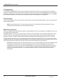
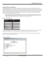
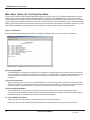
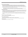
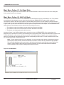
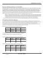
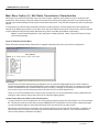
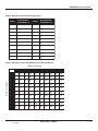
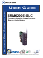
INDUSTRIAL DATA COMMUNICATIONS USER GUIDE SRM6200E-SLC Frequency Hopping Spread Spectrum Ethernet Radio Modem It is essential that all instructions contained in the User Guide are followed precisely to ensure proper operation of equipment. Product User Guide FCC Notification This device complies with part 15 of the FCC rules. Operation is subject to the following conditions: 1) 2) This device may not cause harmful interference and This device must accept any interference received, including interference that may cause undesired operation. The device must be operated as supplied by Data-Linc Group. Any changes or modifications made to the device without the express written approval of Data-Linc Group may void the user’s authority to operate the device. Caution: This device has a maximum transmitted output power of 955 mW. It is required that the transmit antenna be kept at least 23 cm away from nearby persons to satisfy FCC RF exposure requirements. Note: This equipment has been tested and found to comply with the limits for a Class A digital device, pursuant to part 15 of the FCC Rules. These limits are designed to provide reasonable protection against harmful interference in a industrial installation. This equipment generates, uses and can radiate radio frequency energy and, if not installed and used in accordance with the instructions, may cause harmful interference to radio communications. However, there is no guarantee that interference will not occur in a particular installation. If this equipment does cause harmful interference to radio or television reception, which can be determined by turning the equipment off and on, the user is encouraged to try to correct the interference by one or more of the following measures: Reorient or relocate the receiving antenna. Increase the separation between the equipment and receiver. Connect the equipment into an outlet on a circuit different from that to which the receiver is connected. Consult the dealer or an experienced radio/TV technician for help. Note: Whenever any Data-Linc Group SRM series modem is placed inside an enclosure a label must be placed on the outside of that enclosure which includes the modem’s FCC ID. The following antennas are approved for use with Data-Linc Group’s 900 MHz series modems. NOTE: Per FCC Rules, the maximum power allowed at the antenna is 4 Watts E.I.R.P. 900MHz Directional Antenna Gain Manufacturer 8.2 dBi Larsen 12.2 dBi Larsen Manufacture Model Number YA6-900W YA0006 Data-Linc Model Number A-YB A-Y10B 900MHz Omni-Directional Antenna Gain Manufacturer 5.2 dBi Maxrad 7.2 dBi Maxrad 0 dBi Ying Hao 0 dBi Centurion Manufacture Model Number MAX-9053 BMEFC8985HD YH920801/AD-725-A-1 EXC-902-BN Data-Linc Model Number A-OB A-O5B A-06/ADJ A-06BH-3S / 10S (**) (**) This part number refers to an antenna kit(s). The 0 dBi refers to the antenna portion of the kit. Note: The antenna used for this device must be professionally installed on a fixed-mounted permanent outdoor structure for satisfying RF exposure requirements, including antenna co-location requirements of 1.1307(b)(3). DATA-LINC GROUP PN 161-09990-002C SRM6200E-SLC User’s Guide Table of Contents Page Introduction Quick Start ○ ○ ○ ○ ○ ○ ○ ○ ○ ○ ○ ○ ○ ○ ○ ○ ○ ○ ○ ○ ○ ○ ○ ○ ○ ○ ○ ○ ○ ○ ○ ○ ○ ○ ○ ○ ○ ○ ○ ○ ○ ○ ○ ○ ○ ○ ○ ○ ○ ○ ○ ○ ○ ○ ○ ○ ○ ○ ○ ○ ○ ○ ○ ○ ○ Modem Configuration Main Menu Option (0): Set Operation Mode Main Menu Option (1): Set Baud Rate Main Menu Option (2): Edit Call Book Main Menu Option (3): Edit Radio Transmission Characteristics Main Menu Option (4): Show Radio Statistics Main Menu Option (5): Edit Multi-Point Parameters Main Menu Option (8): Password ○ ○ ○ ○ ○ ○ ○ ○ ○ ○ ○ ○ ○ ○ ○ ○ ○ ○ ○ ○ ○ ○ ○ ○ ○ ○ ○ ○ ○ ○ ○ ○ ○ ○ ○ ○ ○ ○ ○ ○ ○ ○ ○ ○ ○ ○ ○ ○ ○ ○ ○ ○ ○ ○ ○ ○ ○ ○ ○ ○ ○ ○ ○ ○ ○ ○ ○ ○ ○ ○ ○ ○ ○ ○ ○ ○ ○ ○ ○ ○ ○ ○ ○ ○ ○ ○ ○ ○ ○ ○ ○ ○ ○ ○ Modem Location Using an External Antenna Modem Front Panel LED’s Sample Data Communication Links ○ ○ ○ ○ ○ Technical Specifications Troubleshooting ○ ○ ○ ○ ○ ○ ○ ○ ○ PN 161-09990-002C rev 3/29/04 ○ ○ ○ ○ ○ ○ ○ ○ ○ ○ ○ ○ ○ ○ ○ ○ ○ ○ ○ ○ ○ ○ ○ ○ ○ ○ ○ ○ ○ ○ ○ ○ ○ ○ ○ ○ ○ ○ ○ ○ ○ ○ ○ ○ ○ ○ ○ ○ ○ ○ ○ ○ ○ ○ ○ ○ ○ ○ ○ ○ ○ ○ ○ ○ ○ ○ ○ ○ ○ ○ ○ ○ ○ ○ ○ ○ ○ ○ ○ ○ ○ ○ ○ ○ ○ ○ ○ ○ ○ ○ ○ ○ ○ ○ ○ ○ ○ ○ ○ ○ ○ ○ ○ ○ ○ ○ ○ ○ ○ ○ ○ ○ ○ ○ ○ ○ ○ ○ ○ ○ ○ ○ ○ ○ ○ ○ ○ ○ ○ ○ ○ ○ ○ ○ ○ ○ ○ ○ ○ ○ ○ ○ ○ ○ ○ ○ ○ ○ ○ ○ ○ ○ ○ ○ ○ ○ ○ ○ ○ ○ ○ ○ ○ ○ ○ ○ ○ ○ ○ ○ ○ ○ ○ ○ ○ ○ ○ ○ ○ ○ ○ ○ ○ ○ ○ ○ ○ ○ ○ ○ ○ ○ ○ ○ ○ ○ ○ ○ ○ ○ ○ ○ ○ ○ ○ ○ ○ ○ ○ ○ ○ ○ ○ ○ ○ ○ ○ ○ ○ ○ ○ ○ ○ ○ ○ ○ ○ ○ ○ ○ ○ ○ ○ ○ ○ ○ ○ ○ ○ ○ ○ ○ ○ ○ ○ ○ ○ ○ ○ ○ ○ ○ Technical Support Return Material Authorization Contact Information ○ ○ ○ ○ ○ ○ ○ ○ ○ ○ ○ ○ ○ ○ ○ ○ ○ 3 4 ○ ○ ○ ○ ○ ○ ○ ○ ○ ○ ○ ○ ○ ○ ○ ○ ○ ○ ○ ○ ○ ○ ○ ○ ○ ○ ○ ○ ○ ○ ○ ○ ○ ○ ○ ○ ○ ○ ○ ○ ○ ○ ○ ○ ○ ○ ○ ○ ○ ○ ○ ○ ○ ○ ○ ○ ○ ○ ○ ○ ○ ○ ○ ○ ○ ○ ○ ○ ○ ○ ○ ○ ○ ○ ○ ○ ○ ○ ○ ○ ○ ○ ○ ○ ○ ○ ○ ○ ○ ○ ○ ○ ○ ○ ○ ○ ○ ○ ○ ○ ○ ○ ○ ○ ○ ○ ○ ○ ○ ○ ○ ○ ○ ○ ○ ○ ○ ○ ○ ○ ○ ○ ○ ○ ○ ○ ○ ○ ○ ○ ○ ○ ○ ○ ○ ○ ○ ○ ○ ○ ○ ○ ○ ○ ○ ○ ○ ○ ○ ○ ○ ○ ○ ○ ○ ○ ○ ○ ○ ○ ○ ○ ○ ○ ○ ○ ○ ○ ○ ○ ○ ○ ○ ○ ○ ○ ○ ○ ○ ○ ○ ○ ○ ○ ○ ○ ○ ○ ○ ○ ○ ○ ○ ○ ○ ○ ○ ○ ○ ○ ○ ○ ○ ○ ○ ○ ○ ○ ○ ○ ○ ○ ○ ○ ○ ○ ○ ○ ○ ○ ○ ○ ○ ○ ○ ○ ○ ○ ○ ○ ○ ○ ○ ○ ○ ○ ○ ○ ○ ○ ○ ○ ○ ○ ○ ○ ○ ○ ○ ○ ○ ○ ○ ○ ○ ○ ○ ○ ○ ○ ○ ○ ○ ○ ○ ○ ○ ○ ○ ○ ○ ○ ○ ○ ○ ○ ○ ○ ○ ○ ○ ○ ○ ○ ○ ○ ○ DATA-LINC GROUP ○ ○ ○ ○ ○ ○ ○ ○ ○ ○ ○ ○ ○ ○ ○ ○ ○ ○ ○ ○ ○ ○ ○ ○ ○ ○ ○ ○ ○ ○ ○ ○ ○ ○ ○ ○ ○ ○ ○ ○ ○ ○ ○ ○ ○ ○ 6 8 10 10 12 16 18 21 22 22 23 25 27 28 29 29 29 1 SRM6200E-SLC User’s Guide 2 DATA-LINC GROUP PN 161-09990-002C rev 3/29/04 SRM6200E-SLC User’s Guide Introduction Data-Linc Group’s SRM6200E-SLC has been designed to mount in an Allen-Bradley SLC 500 Slot Rack. The SRM6200ESLC transceiver modem is a high performance, wireless radio modem designed for heavy-duty industrial data communications in the 902-928 MHz license-free band. It employs advanced spread spectrum frequency hopping and error detection technology to achieve very reliable, noise and interference immune operation. A high RF data rate of 188kbps and superior sensitivity provide ultra reliable data integrity. The SRM6200E-SLC has a rated range of up to 25 miles (40 km) and an installed range of up to 35 miles (56 km) in optimal conditions with line-of-sight and an omni directional antenna. This can also be extended further with repeaters or higher gain antenna. The SRM6200E-SLC can be operated in a number of different modes to satisfy a broad range of communications requirements. It can be configured for point-to-point or multi-point operation with an unlimited number of remote sites on a single master depending on data throughput requirements. Repeaters can be used in the system to extend range and eliminate dead RF zones that are blocked by obstructions. An external antenna can be used with up to two hundred feet of coax. This provides a boost in signal strength and decreases induced noise levels. With an external antenna, radio modems can be located inside buildings or metallic enclosures. Equipped with a 10 Base-T Ethernet port, the SRM6200E-SLC is easily connected via standard 10 Base-T Category 5 patch cord (provided) to an Allen-Bradley SLC 5/05 CPU ENET port, hub or any other device equipped with a 10 Base-T network interface. The User Guide covers the operating modes and configurations that are available to users of the SRM6200E-SLC. It also provides the user with bench testing instructions, technical information and specifications. In most applications, the SRM6200E-SLC comes pre-configured for the application in which it is going to be used. In most cases no other configuration is required. If you are unsure if the modem needs further configuration, please contact Data-Linc Group. PN 161-09990-002C rev 3/29/04 DATA-LINC GROUP 3 SRM6200E-SLC User’s Guide Quick Start The SRM6200E-SLC comes pre-configured for your application (unless otherwise requested). In most cases, configuration settings are not required. Although each modem is tested before shipment, it is recommended that a bench test be done before the modem is installed in its application. In all applications, there is a master modem and one or more remotes. Some applications may also have one or more repeaters. This “Quick Start” will assume that there is a repeater in the system. If there is not, ignore the parts that talk about repeaters, as the remote modems should operate the same with or without repeaters. The SRM6200E-SLC is available in three different power configurations: • SRM6200E-SLC is a 12VDC powered device that is designed to take 12VDC in on the barrel jack on the front panel. • SRM6200E-SLC/BP is a 24VDC powered device that receives power directly from the backplane and does not need a separate power supply. Be sure that your 1746 chassis has a large enough supply — Data-Linc Group recommends the use of the P-4 power supply chassis (a wall transformer power supply has been included for bench testing purposes). • SRM6200E-SLC/24V is a 24VDC powered device that is designed to take 24VDC in on the removable screw terminal connector on the front panel (please note the polarity: positive side marked “+” on the top if you are supplying your own power). Locate the modem labeled “Master” and connect its power supply to an appropriate 120VAC power source, then connect it to the modem. The “P” LED should come on and stay on Note: on all modems, the “RF Link” LED will come on for the first few seconds after power up. Next, locate the modem(s) labeled “Repeater” and connect to power. The LED “P” and “RF Link” should come on and stay on. Now locate the modem(s) labeled “Remote” and connect to power. The LED “P” and “RF Link” should come on and stay on. The modems are now ready to carry Ethernet data. Connect the “Master” and “Remote” (or “Repeater/Remote” if your network has one) to the Ethernet equipment that has been pretested for operation. The device has been designed with a crossover switch. The crossover function interchanges the transmit and receive pairs removing the need for a crossover cable in certain situations. The SRM6200E-SLC crossover switch has been factory set in the crossover position. If the system is connected and the LAN link LED is not lit, the crossover switch (SW3- Diagram 3, pg. 24) may need to be moved to the straight through position. 4 DATA-LINC GROUP PN 161-09990-002C rev 3/29/04 SRM6200E-SLC User’s Guide To change the crossover switch remove the SRM6200E-SLC from the Allen-Bradley SLC500 Slot Rack. Under the edge of the enclosure is a black and silver slide switch (S3- Diagram 3, page 24). If connecting to an Ethernet hub, the crossover switch should be set in the straight through (left) position. If connecting to a PC, PLC or most other Ethernet interface equipped devices, the crossover switch should be set in the crossover (right) position. Note: The SRM6200E-SLC will not support “Peer to Peer” communications. The equipment that is attached to the SRM6200E-SLC must be capable of operating in a “Master (host) to Remote” network. It is recommended that a “Ping” test be done at this point. This can be done in either direction, but remember that only a “Master to Remote” or “Remote to Master” connection can be established through the modems. Also note that because of the MAC filtering done by the modems, if you take a piece of Ethernet equipment on one side of the SRM6200E-SLC network and move it to the other side of said network, you must power down both the “Master” and the effected “Remote” in order to re-establish connectivity through the modems. If powering down the modem is not practical to the applications, the modems will rebuild the MAC filter table in approximately six minutes and communications should return. Once a successful “Ping” test has been done, the modems are ready for communication. If the “Ping” test was not successful, please refer to the trouble shooting section of this manual or contact Data-Linc Group tech support for assistance. PN 161-09990-002C rev 3/29/04 DATA-LINC GROUP 5 SRM6200E-SLC User’s Guide Configuration In most cases, the SRM6200E-SLC comes pre-configured from the factory. However, it may sometimes be necessary to change the configuration. Most parameters are changed in the radio section of the modem although there are a few settings that are set using switches. If you are not sure if you need to change the configuration of the SRM6200E-SLC, you probably don’t. Please contact Data-Linc Group for further information if you are unsure about your configuration. Switch Settings To access the switches, remove the modem from the SLC Rack. The switch bank (SW1-Diagram 3, pg. 24) is located in the center of the large PCB. Note: Leave switch positions 4, 5 and 6 at factory setting of off unless otherwise directed by Data-Linc Group. Changing these switches requires a radio parameters change. MAC Filtering Function All devices capable of generating Ethernet traffic have a MAC (Medium Access Control) address. This address is used in the communications of Ethernet data. The SRM6200E-SLC is factory set to perform MAC level filtering. This means that it learns all the MAC addresses from the LAN it is connected to, and only forwards data packets across the radio links which are destined for addresses located across the radio link. The MAC filtering function is enabled by setting switch (SW2-Diagram 3, pg.24) to the on position. The MAC address table can store up to 10,000 addresses. Each entry to the table has a lifetime of six minutes after which the address is deleted. This dynamic table building allows for the possibility of stations being removed from the LAN. The net result of this filtering functionality is the reduction of unnecessary network traffic across the radio link. Note: Many Ethernet networks have data packets that are not covered by the MAC filter function (broadcast packets for example). These packets can occupy tremendous amount of the network’s bandwidth and overwhelm the SRM6200E-SLC section of the network. If the SRM6200E-SLC’s are going to be installed where they are linked to an open network (on office network, etc.), a properly configured router or switch should be installed to protect the modems from excessive data traffic. If you are unsure about your network, please consult with your network administrator. 6 DATA-LINC GROUP PN 161-09990-002C rev 3/29/04 SRM6200E-SLC User’s Guide Radio Parameter Configuration The SRM6200E-SLC allows you to set several parameters to suit your particular application. All adjustments are done through the SRM6200E-SLC setup program, a user interface that eliminates the need for setup diskettes or custom software. To access the configuration menu, connect the radio modem’s configuration port to any terminal program with port settings of 19.2Kbaud, 8 data bits, no parity and one stop bit. With the modem connected to the PC running the terminal program, press the Configure button. While any terminal program will work, examples for this manual were generated using the Microsoft Windows 2000 application “HyperTerminal.” Note: When using HyperTerminal, set Handshaking to none and use a standard straight through cable. If you are using something other than HyperTerminal, it may be necessary to use a cable that has pins 4 and 6 connected together on the modem side of the cable. Contact Data-Linc for further information. Table 1: Terminal Settings Parameter Setting Baud Rate 19200 Data Bits 8 Parity None Stop Bits 1 Flow Control None When the setup program is invoked the RF “IN” LED on the SRM6200E-SLC front panel will flash once when the Configure button is pressed and the RF “Link” LED will remain on for the entire time the radio modem is in setup mode. The main menu provides the radio modem’s unique call book number and the set of choices for editing the operational parameters and viewing the performance data. Figure 1: Main Menu PN 161-09990-002C rev 3/29/04 DATA-LINC GROUP 7 SRM6200E-SLC User’s Guide Main Menu Option (0): Set Operation Mode When item (0) is selected, the Operation Mode Menu appears as shown in figure 2. The Operation Mode option is used to designate the method in which the particular SRM6200E-SLC will be used. The SRM6200E-SLC operates in a master to remote configuration; therefore, any radio modems that are intended to operate together must be set up as such. In a pointto-point setup, either the Master or Remote may be used on either end of the communications link. One consideration when setting up the radio modems is that a number of parameters are controlled by the settings in the Master; therefore, you may wish to deploy the Master on the communications end where you will have easier access to the radio modem. Figure 2: Mode Menu Shown below are example settings. Please refer to supplied configuration sheets for your modem’s configuration. (0) Point-to-point Master The SRM6200E-SLC operates in a master/remote configuration. When designated as a master in point-to-point mode, the radio modem will call any or all remotes it is instructed to call in the call book. The Master determines the settings used for all Radio Transmission Characteristics (except power), regardless of the settings in the remotes and/or repeaters. (1) Point-to-Point Remote When set up as a point-to-point remote, an SRM6200E-SLC will communicate with any master in its call book, either directly or through one or two repeaters. When functioning as a remote, the Entry to Call feature in the radio modem’s call book (Figure 3) is not operational. The remote will communicate with any master on the list that calls. (2) Point-to-Multi-Point Master The SRM6200E-SLC may be set to run in multi-point mode, which allows one master to simultaneously be in communication with numerous remotes. A point-to-multi-point master will communicate only with other radio modems designated as point-to-multi-point remotes or point-to-multi-point repeaters. (3) Point-to-Multi-Point Remote Setting (3) allows the radio modem to operate as a remote in a multi-point network. Please refer to the section entitled multi-point operation, for more information on running a multi-point network. 8 DATA-LINC GROUP PN 161-09990-002C rev 3/29/04 SRM6200E-SLC User’s Guide (4) Point-to-Point Remote/Repeater Option 4 allows you to designate the radio modem to act as either a remote or a repeater, depending upon the instructions received from the master for the specific communications session. When a radio modem is placed in an ideal location, this setting offers the flexibility of using that radio modem as an end point in the communications link (remote) or to extend the link to a further point (repeater). These functions are not, however, available simultaneously (the radio modem cannot act as both a remote and a repeater at the same time). Note: Configured as a repeater, a radio modem has no security features as explained below. When a radio modem is designated as a Point-to-Point Remote/Repeater, it will allow any master to use it as a repeater. (5) Point-to-Point Repeater SRM6200E-SLC radio modems allow the use of up to two repeaters in a communications link, significantly extending the operating range. When designated as a repeater, a radio modem behaves as a pass-through link. All settings for the call book, baud rates, and radio transmission characteristics are disabled. A repeater will connect with any master that calls it (the repeater must still be set up in the master’s call book). The use of one repeater in a communications link will reduce the top data throughput available when compared to a direct master to remote link (generally on the order of 50%). The throughput does not decrease further if two repeaters are used. (6) Point-to-Point Remote/Master Switchable Mode 6 is not applicable to the SRM6200E-SLC radio modems. (7) Point-to-Multi-Point Repeater Setting (7) allows the radio modem to operate as a repeater in a multi-point network. Please refer to the section entitled, multi-point operation, for more information on running a multi-point network. (F) Ethernet options This selection is factory set and should not be changed. PN 161-09990-002C rev 3/29/04 DATA-LINC GROUP 9 SRM6200E-SLC User’s Guide Main Menu Option (1): Set Baud Rate The baud rate setting affects the interface between the radio and Ethernet sections of the modem. All of the settings are factory set and should not be changed. Main Menu Option (2): Edit Call Book The Call Book is an innovative feature in the SRM6200E-SLC that offers both security and flexibility in use. The Call Book accomplishes this by allowing the user to determine with which other SRM6200E-SLCs a given radio modem will communicate, based on the call book numbers for both the Master and Remote. The radio modem’s call book number is encoded in the microprocessor and identified on a label on the modem. The instructions provided in this section are for pointto-point mode only. Use of the Call Book for multi-point systems is explained later in this chapter. For two SRM6200E-SLC radio modems to communicate in point-to-point mode, three events must occur: 1. The call book number for the Master must be listed in the Remote’s Call Book. 2. The call book number for the Remote must be listed in the Master’s Call Book. 3. The Master must be programmed to call the remote. As shown in figure 3, the Call Book allows users to set up a list of up to 10 SRM6200E-SLCs to communicate with, designate up to 2 repeaters to be used in communicating with a given radio modem, and tell the Master which remote to call. To direct the Master to call a remote, the Remote must be in the Call Book Menu. A specific remote may be called by entering (C) at the prompt, followed by the menu number corresponding to that remote. To call any available remote in the list, the user should enter C and then A (for All). Note: To call a remote through one or two repeaters, you must call that remote directly (as opposed to using the Call All option). When Call All is selected, the Master is not able to connect with any remotes through repeaters. This is because the Master calls every remote in the list when instructed to call all and will connect with the first remote to respond. When calling through a repeater, the Master must first call that Repeater and establish a communications link with it prior to making contact with the Remote. Figure 3: Call Book Menu 10 DATA-LINC GROUP PN 161-09990-002C rev 3/29/04 SRM6200E-SLC User’s Guide Entering or Modifying Numbers in the Call Book Entering or modifying call book numbers in the Call Book is a straightforward process. When in the Call Book menu select the entry number (0 – 9) you wish to edit. You will be prompted for the new number (formatting is automatic, you do not need to enter the dash). Once the number is entered (unless it is 000-0000) you will be asked for the call number of the first repeater to be used. If no repeater is to be used, enter the escape key; your entry will be complete and you will be back in the Call Book menu screen. If you enter a repeater number you will then be prompted for the call number of the second repeater to use. If a second repeater is being used, enter the call number at this time; if not then enter the escape key. Once again, the radio modem will retain your entries, as shown in the updated Call Book menu screen. Note: It is important that the Call Book slots (0 – 9) are filled sequentially beginning with 0, the first slot in the book. Call book numbers do not need to be entered in numerical order; however, there must not be any 000-0000 numbers in the middle of the list of good call book numbers. The reason for this is that when a master is instructed to Call All available remotes, it will call all remotes listed until it reaches the number of 000-0000. If a valid call book number is entered after the all zero number, it will not be recognized as a valid number to be called by the Master. Edit Call Book in Multi-Point Systems In a multi-point system the Remotes and Repeaters are not listed in the Master’s Call Book. When establishing such a system, it is necessary only to have the Master’s call book number in each Remote’s and Repeater’s Call Book, and to have each repeater’s call book number in the Call Book of each remote which may potentially communicate through it. The following example shows the Call Books of a multi-point system comprised of a master, repeater and remote in which the Remote can communicate either through the Repeater or directly to the Master: Multi-Point Master Call Book (Unit Call book number 555-0001) Entry Number (0) 000-0000 (1) 000-0000 Repeater 1 Repeater 2 No call book number entries are necessary in the Master’s Call Book The Master’s Call Book may be programmed to call any entry Multi-Point Repeater Call Book (Unit Call book number 555-0002) Entry Number (0) 555-0001 (1) 000-0000 Repeater 1 Repeater 2 Multi-Point Remote Call Book (Unit Call book number 555-0003) Entry Number (0) 555-0001 (1) 555-0002 (2) 000-0000 PN 161-09990-002C rev 3/29/04 Repeater 1 Repeater 2 DATA-LINC GROUP 11 SRM6200E-SLC User’s Guide Main Menu Option (3): Edit Radio Transmission Characteristics When option (3) is selected in the main menu, the screen in figure 4 appears, which allows the user to modify the radio transmission characteristics of the radio modems. As stated in the warning, these parameters are for the experienced user who has a good understanding of the principles of radio data transmission. They should be changed only after consulting this manual. It is important to note that the radio parameters between any radio modems in communication will be determined by the settings for the Master (except when in multi-point mode, see (4) RF Data Rate and (5) RF Power below). While the settings may be modified for the Remote(s) and/or Repeaters, they will be overridden by the Master’s parameters. Note: For most Ethernet applications, these settings are already optimized. Please consult with Data-Linc Group before making changes. Figure 4: Radio Parameters Menu Shown below are example settings. Please refer to supplied configuration sheets for your modem’s configuration. (0) FreqKey Selection (0) in the Radio Parameters menu allows the user to modify the hopping patterns of the radio modems to minimize the interference with other SRM6200E-SLC radio modems in operation in the area. For instance, if there were 10 pairs of SRM6200E-SLCs in operation within a factory or refinery, changing the Frequency Key would ensure that they would not jump onto the same frequencies at the same time for the same length of time. There are 15 choices available for the Frequency Key (0-9 and A-E). It is recommended that a list be maintained of the settings for each master to ensure that each is set to a different hopping pattern. (1) Max Packet Size and (2) Min Packet Size Selections (1) and (2) allow the user to designate the size of the packets (in bytes) used by the radio modem in its communications link. This may be of particular value when using the SRM6200E-SLC with different communications software packages; you may find that throughput is optimized when packet sizes are restricted by the radio modem. Packet size is determined by a combination of the settings entered by the user and the RF Data Rate. In addition, the Max Packet Size is a function of the setting selected for the Min Packet Size. Tables 2, 3 and 4 provide the packet sizes for each different combination of settings. 12 DATA-LINC GROUP PN 161-09990-002C rev 3/29/04 SRM6200E-SLC User’s Guide Table 2: Minimum Packet Size Settings (bytes) Setting Min Packet Siz e RF Data Rate = 2 Setting Min Packet Siz e RF Data Rate = 3 0 16 0 8 1 21 1 12 2 26 2 16 3 32 3 20 4 37 4 24 5 42 5 28 6 48 6 32 7 53 7 36 8 58 8 40 9 64 9 44 Table 3: Maximum Packet Size Settings where RF Data Rate=3 Minimum Setting Maximum Setting 0 1 2 3 4 5 6 7 8 9 0 8 24 40 56 72 88 104 120 136 152 1 12 28 44 60 76 92 108 124 140 156 2 16 32 48 64 80 96 112 128 144 160 3 20 36 52 68 84 100 116 132 148 164 4 24 40 56 72 88 104 120 136 152 168 5 28 44 60 76 92 108 124 140 156 172 6 32 48 64 80 96 112 128 144 160 176 7 36 52 68 84 100 116 132 148 164 180 8 40 56 72 88 104 140 136 152 168 184 9 44 60 76 92 108 124 140 156 172 188 PN 161-09990-002C rev 3/29/04 DATA-LINC GROUP 13 SRM6200E-SLC User’s Guide Table 4: Maximum Packet Size Settings where RF Data Rate=2 Minimum Setting Maximum Setting 0 1 2 3 4 5 6 7 8 9 0 15 36 58 79 100 121 143 164 185 206 1 20 42 63 84 105 127 148 169 190 212 2 26 47 68 90 111 132 153 175 196 217 3 31 52 74 95 116 137 159 180 201 222 4 36 58 79 100 121 143 164 185 206 228 5 42 63 84 105 127 148 169 190 212 233 6 47 68 90 111 132 153 175 196 217 238 7 52 74 95 116 137 159 180 201 222 244 8 58 79 100 121 143 164 185 206 228 249 9 63 84 95 127 148 169 190 212 233 254 (3) Xmit Rate There are two settings for the Transmit Rate parameter. For normal operation, the SRM6200E-SLC should be set at Transmit Rate 1. Transmit Rate 0 is useful to qualitatively gauge signal strength. When set to Transmit Rate 0 the radio modems will transmit data back and forth continuously, and the strength of the signal may be gauged by viewing the “Show Radio Statistics” option. Due to the fact that the radio modems transmit continuously when Transmit Rate is set to 0 (whether or not they have data to send) they use radio frequency spectrum unnecessarily. Therefore, Transmit Rate 0 should be used only as a diagnostic tool and not for normal operation. (4) RF Data Rata The SRM6200E-SLC has two settings for the RF Data Rate (the speed that the modems talk to each other). Setting 2 should be used when the radio modems are close together and data throughput is to be optimized. Setting 3 should be used when the radio modems are farther away and a solid data link is preferred over data throughput. Note: The RF Data Rate setting must be identical for all units in the system. Any radio modem with a different RF Data Rate than the master will not establish a communication link. 14 DATA-LINC GROUP PN 161-09990-002C rev 3/29/04 SRM6200E-SLC User’s Guide (5) RF Xmit Power The SRM6200E-SLC offers users the ability to modify the Transmission Power of the radio modem. There are 10 power settings available (1-10) which are roughly linear. Therefore a setting of 10 is full power or (1 Watt) and 1 is 10% power (or 100 mw). The following guidelines should be followed when setting the RF Transmission Power: Table 5: Power Transmit Settings Setting P o w er L evel Used When 1-3 Low Pair of pairs of radio modems operating within the same or adjoning rooms. 4-6 Medium More than one pair of radio modems operating withi the same facility. 7-10 Full Normal operation extending beyond a facility. (6) Remote Security With option 6 the user may disable the radio modem’s security so it will accept a call from any other SRM6200E-SLC. The default setting is 0 where security is enforced (the caller’s call book number must be in the Remote’s Call Book). With a setting of 1 security is disabled. (7) RTS to CTS This setting is not applicable to the SRM6200E-SLC and should not be changed from the factory setting (the factory setting is 0) (8) Retry Time Out The Retry Time Out parameter allows the use to determine when a remote will drop a connection to a master or repeater in multi-point mode. The default setting is 255, meaning that if one packet in 255 from the Master is sent successfully to the Remote it will maintain a link. The lowest setting is 8, at which a remote will drop a connection much faster. The Retry Time Out parameter is useful when a multi-point system is used with a moving master or remotes. As the link gets weaker, a lower setting will allow a remote to drop it’s link and search for a stronger connection. While intended primarily for multi-point systems, the Retry Time Out parameter may also be modified in point-to-point systems. In point-to-point mode the Retry Time Out should not be set to a value of less than 151. (9) Lowpower Mode The Lowpower Mode is not applicable to the SRM6200E-SLC. This setting should not be changed. (A) High Noise Use the menu to indicate if the modem will be operated in an environment with a high degree of radio noise and interference. With a setting of 1, the rejection of interference is improved, at the cost of reduced range and/or throughput. (B) MCU speed This setting is factory set to 1 (high speed) and should not be changed. PN 161-09990-002C rev 3/29/04 DATA-LINC GROUP 15 SRM6200E-SLC User’s Guide Main Menu Option (4): Show Radio Statistics Option (4) in the main menu allows the user to view data transmission statistics which have been gathered by the Transceiver during the most recent session. Statistics are gathered during each data link and are reset when the next link begins. Ideally, noise levels should be below 30, and the difference between the average signal level and average noise level should be 30 or more. High noise levels tend to indicate other sources of RF interference, while low signal levels indicate a weak link. The “Local” stats are the statistics that are being gathered by the modem you are connected too while “Remote1, Remote2, and Remote3” are the stats of the Repeater(s) that the modem you are attached to is using to get back to the Master modem. The following sections provide information useful to the process of troubleshooting and improving radio links. Average Noise Level The average noise level indicates the level of background noise and interference at this modem and at each of the modems used as repeaters in the link. The number is an average of the noise levels measured at each frequency in the modems’ frequency hop table. The individual measurement values at each frequency hop channel are shown in the frequency table. The frequency table is accessed by pressing the ENTER key on the computer when the radio statistics menu is displayed. Average noise levels will typically fall in the range of 15 to 30. Average noise levels significantly higher than this are an indication of a high level of interference that may degrade the performance of the link. High noise levels can often be improved with bandpass filters, antenna placement or antenna polarization. Please contact Data-Linc Group for more information. Average Signal Level The average signal level indicates the level of received signal at this modem and at each of the modems used as repeaters in the link. For each of these, the signal source is the modem that transmits to it. The number is an average of the received signal levels measured at each frequency in the modem’s frequency hop table. The individual measurement values at each frequency hop channel are shown in the frequency table. The frequency table is accessed by pressing the ENTER key on the computer when the radio statistics menu is displayed. For a reliable link, the average signal level should be at least 30 greater than the average noise level reading. The table below provides an approximate conversion of average signal level values into the more common dBm (decibel milliwatts). Low Average Signal Levels can often be corrected with higher gain antennas, antenna placement, and use of repeaters. Contact Data-Linc Group for more information. Average Signal Level 41 49 60 66 85 Level in dBm -110 -100 -60 -80 -70 Overall Receive Rate (%) The Overall Rcv Rate measures the percentage of data packets that were successfully transmitted from the Master to the Remote on the first attempt without requiring retransmission. A number of 75 or higher indicates a robust link that will provide very good performance even at high data transmission rates. A number of 25 or lower indicates a weak or marginal link that will provide lower data throughput. An Overall Rcv Rate of 100% will provide approximately 90 Kbaud of bandwidth with an RF data rate of 3 (Radio Transmission Parameters Menu) and approximately 110 Kbaud of bandwidth with an RF Data Rate of 2. These numbers are reduced approximately 50% if there are one or more repeaters in the network. 16 DATA-LINC GROUP PN 161-09990-002C rev 3/29/04 SRM6200E-SLC User’s Guide Number of Disconnects If, during the course of performing a link test, the link between the master and the slave is broken, and the radios lose carrier detect, the occurrence is recorded in the Number of Disconnects value. The value indicates the total number of disconnects that have occurred from the time the link test started until the radio was put into config mode. Under normal operating conditions, the number of disconnects should be 0. One or more disconnects may indicate a very weak link, the presence of severe interference problems or loss of DC power to the Master or Repeater if one is present. Note: A remote and/or repeater will record a disconnect if the system master is placed into configuration mode or has power interrupted while the remote and/or repeater is linked to the master. Radio Temperature The radio temperature value is the current operating temperature of the radio in degrees C (Celsius.) For proper operation, SRM6200E-SLC radio modems must be in the range of –400 to 750 C. Multi-Point Operation In a multi-point system, a radio modem designated as a master is able to simultaneously be in communication with numerous remotes. In its simplest form, a multi-point network functions with the Master broadcasting its messages to all remotes and the Remotes responding to the Master as appropriate. Traditionally, a multi-point network is used in applications where data is collected from many instruments and reported back to one central site. As such, the architecture of such a system is completely different from point-to-point applications. The theoretical maximum number of remotes that can be configured into a multi-point network is a function of the data throughput needed from each of the remotes. For example, if the network will be polling remotes once a day to retrieve sparse data, several hundred remotes could be configured to a single master. If, on the other hand, each remote will be transmitting data at greater levels then fewer remotes may be connected to the Master (the overall system will be closer to capacity with fewer remotes). The theoretical limit of a multi-point system is influenced by the following parameters: • • • • Size of the blocks of data— the longer the data blocks the greater the system capacity Throughput The amount of contention between remotes Use of repeaters— a single repeater in a multi-point network will decrease overall system capacity by 50%; more than one repeater does not further decrease network capacity PN 161-09990-002C rev 3/29/04 DATA-LINC GROUP 17 SRM6200E-SLC User’s Guide Main Menu Option (5): Edit Multi-Point Parameters Figure 5: Multi-Point Parameters Shown below are example settings. Please refer to supplied configuration sheets for your modem’s configuration. In a multi-point network, it is critical to know how many radio modems are being used as repeaters. Any radio modem that is used as a repeater essentially becomes a master to the Remotes and other repeaters to which it is communicating. Therefore, the user must first identify how many repeaters are connected to the Master by assigning a value in parameter (0) Number Repeaters. This parameter must also be set for each repeater in the system (i.e., in the event that a repeater is connected to one or more other repeaters). This parameter does need to be set for multi-point remotes. In point-to-point operation, the SRM6200E-SLC radio modems acknowledge every data packet transmitted. In a multi-point network, the Remotes do not acknowledge transmissions from master to remotes. This is to prevent system overload. If the Remotes acknowledged all data transmissions from the Master in a large multi-point system, then all system capacity would be spent having the Master listen for acknowledgments from the Remotes. Because the transmission is not acknowledged by the Remotes, 100% confidence does not exist that every remote has received every message from the Master. To address this issue the user may modify option (1) Master Packet Repeat, assigning a value between 0 (the packet is transmitted once) to 9 (the packet is repeated 9 times). For networks with solid RF links, this parameter would be set at the lower end of the scale (0-1). If the network has some weak or marginal links it would be set toward the higher values. If a remote receives a packet from a master more than once it will discard the repeated packets received. While packets transmitted from the Master to the Remotes in a multi-point network are not acknowledged, packets transmitted from remotes to the Master are acknowledged. However, it is possible that more than one remote will attempt to transmit to the master at the same time, and it is therefore important that a protocol exists to resolve contention for the Master between remotes. This is addressed through parameters (2) Max Remote Retry and (3) Retry Odds. The Max Remote Retry setting defines how many times (0 to 9) the Remote will attempt to retransmit a packet to the Master before beginning to use a back-off algorithm. Once the Remote has unsuccessfully attempted to transmit the packet the number of times specified in Max Remote Retry it will attempt to transmit to the master on a random basis. 18 DATA-LINC GROUP PN 161-09990-002C rev 3/29/04 SRM6200E-SLC User’s Guide The Retry Odds parameter determines the probability that the Remote will attempt to retransmit the packet to the Master; a low setting will assign low odds to the Remote attempting to transmit and conversely a high setting will assign high odds. An example of how this parameter might be used would be when considering two different remotes in a multi-point network, one close in with a strong RF link and the other far from the Master with a weak link. It may be desirable to assign a higher Retry Odd to the Remote with the weaker link to give it a better chance of competing with the closer Remote for the Master’s attention. Another parameter in a multi-point network is (4) DTR Connect. This setting is not applicable in the SRM6200E-SLC’s and should not be changed from a factory default of 0. The Repeater’s hopping pattern must also be set in a multi-point network; this is accomplished with parameter (5) Repeater Frequency. Setting this parameter is in contrast with point-to-point mode where the Repeater automatically uses the Master’s hopping pattern. The Repeater may be programmed to either use the Master’s hopping pattern selection (0) or its own selection (1). Option (6) NetWork ID allows multi-point networks to be established without the use of the Call Book. If the NetWork ID is set to any value lower than the default (255) the Remotes in the multi-point network will communicate with the first multi-point master or repeater heard with the same NetWork ID. When the NetWork ID is used multi-point masters and repeaters may be replaced without reprogramming all of the Remotes in the network. In addition, this allows a remote to establish communications with different masters (though not at the same time) without having the call book numbers in the Call Book. This is very useful in mobile multi-point applications. (8) Multi Master Synch is reserved for multi-point applications with concentrations of master units where it is necessary to reduce interference between the Masters. Please contact the factory for more information on the use of this feature. (9) 1PPS Enable/Delay This setting is not applicable to the SRM6200E-SLC and should not be changed from the factory default of 255. (A) Remote/Repeater The Remote/Repeater mode allows a SRM6200E-SLC in a multi-point system to simultaneously act as a remote and a repeater. When in this mode a SRM6200E-SLC will repeat any packets sent from a master as well as send them out the Ethernet port. This gives a SRM6200E-SLC set as a repeater to act as a remote at the same time. 0 disables this mode, 1 enables it. For this feature to work, the modem must be configured as a point-to-multipoint repeater. (B) Diagnostics The SRM6200E-SLC has the ability to run a diagnostic program while in normal operations. Contact the factory for additional information. (C) SubNet ID The default setting is “Disabled.” Please see the SubNet ID section of this manual. (D) Radio ID Used with the Diagnostics. Contact the factory for additional information. PN 161-09990-002C rev 3/29/04 DATA-LINC GROUP 19 SRM6200E-SLC User’s Guide SubNet ID The SRM6200E-SLC series modems offer a SubNet ID system for use in multi-point networks using Network ID. This feature allows the users to dictate what path a given repeater or remote will use to achieve a link to the network Master. For example, if a remote modem in a given network has line of sight to the network Master and one or more repeaters, but only one repeater is close to that Remote, SubNet ID can be used to link that Master with the proper Repeater only. Note: This feature can only be used in networks using Network ID with one or more repeaters. There are two components to SubNet ID. The first is the Xmit (transmit) SubNet ID, and the second is Rcv (receive) SubNet ID. The Xmit SubNet ID is used only by repeaters and is the ID that a repeater sends out when sending data to other repeaters or remotes. The Rcv SubNet ID is the ID that repeaters or remotes look for to receive data. Note: The master is not affected by these settings. Only repeaters and remotes use these settings. Remotes only use Rcv SubNet ID. Modem configurations are as follows (see diagram 1 below): Master No setting used Repeaters Any repeater that should be linked directly to the Master should have the Rcv SubNet ID set to 0. Any repeater using another repeater as its link, needs the Rcv SubNet ID set to the Xmit SubNet ID of that Repeater. The Xmit SubNet ID can be set to anything from 1 to E. Remotes Any remote that should be linked directly to the Master should have the Rcv SubNet ID set to 0. Any remote using a repeater as its link should have the Rcv SubNet ID set to the Xmit SubNet ID of that Repeater. Diagram 1 Rcv = 0 Xmit =1 Xmit/Rcv not set Ethernet Radio Modem LAN Link In Out B A Radio Configuration -V +V OE Coll Use A or B for Lan Link Ethernet Radio Modem RF Power 10BaseT LAN Link In Power Link Reset/ Confg Rcv = 1 Xmit =2 Out Out In B A 10BaseT -V +V Coll 10 to 28 VDC Use A or B for Lan Link Ethernet Radio Modem RF Power Radio Configuration OE LAN Link In Power Link Reset/ Confg Out In Out Coll 10 to 28 VDC 10BaseT RF Power Radio Configuration -V Power +V OE Link Reset/ Confg Out In 10 to 28 VDC Use A or B for Lan Link Repeater 1 Master B A Repeater 2 Rcv not set Xmit not set Ethernet Radio Modem LAN Link In Out B A 10BaseT RF Power Radio Configuration -V Power +V OE Link Reset/ Confg Out In Coll Use A or B for Lan Link 10 to 28 VDC Remote 4 Rcv = 0 Xmit not set Ethernet Radio Modem LAN Link In Out B A 10BaseT -V Power +V OE Link Reset/ Confg Out In Coll Use A or B for Lan Link 10 to 28 VDC LAN Link In Out B A 10BaseT 20 RF Power Power Radio Configuration -V +V OE Coll Use A or B for Lan Link Remote 1 Ethernet Radio Modem Ethernet Radio Modem RF Power Radio Configuration Rcv = 2 Xmit not set Rcv = 1 Xmit not set Link Reset/ Confg LAN Link In Out Out In Coll 10 to 28 VDC Remote 2 DATA-LINC GROUP B A 10BaseT RF Power Radio Configuration -V Power +V OE Link Reset/ Confg Out In Use A or B for Lan Link 10 to 28 VDC Remote 3 PN 161-09990-002C rev 3/29/04 SRM6200E-SLC User’s Guide Main Menu Option (8): Password Caution: If the password feature is enabled and you cannot remember the password, the radio modem will have to be returned to Data-Linc Group to have the password disabled. Use with caution. Option (8) in the Main Menu allows the user to set a password which will prevent unauthorized users to change the configuration of the modem. Setting a Password To enable the Password feature choose (8) from the Main Menu. You will be prompted with “New PW? (<esc> to exit) To back out of the process and not enable the password, hit escape. To set a password type in exactly 4 characters. At any point in the process you can cancel by hitting the escape key. Once the 4 characters have been entered you will be prompted with “<enter> to accept, <esc> to quit”. At this point, if you wish to accept the password entered and enable the feature, press the enter key. The password that you have chosen is displayed on the line above (please note that the password is case sensitive). To quit the process and not enable the password press escape. Changing a Password Once the password feature has been enabled it is possible to change to a new password. To enter a new password select (8) from the Main Menu. You will be prompted with “Enter Security Code”. Enter the current password. Once the password has been entered correctly (it is case sensitive) you will be prompted to enter the new password. At any point this process may be cancelled by pressing escape. Disabling Password The process to disable the password is similar to the process to change the password. However, when prompted to enter the new password, the following procedure needs to be followed: 1. Hold the “Alt” key down and using the number key pad (not the numbers across the top of the key board) type “0255” 2. Release the “Alt” key 3. Repeat steps 1 and 2 three more times (this will enter 0255 a total of four times). 4. You will be prompted with “<Enter> to accept, <esc> to quit 5. Hit the “Enter” key to disable the password or hit the escape key to keep the password PN 161-09990-002C rev 3/29/04 DATA-LINC GROUP 21 SRM6200E-SLC User’s Guide SRM6200E-SLC Location Selection Placement of your SRM6200E-SLC is likely to have a significant impact on its performance. In general, the rule of thumb with the SRM6200E-SLC is that the higher the placement of the antenna the better the communication. In practice you should also place the radio modem itself away from computers, telephones, answering machines, and other similar equipment. To improve the data link, Data-Linc Group offers directional and omni directional antennas with cable lengths ranging from 10 to 250 feet. When using an external antenna, placement of that antenna is critical to a solid data link. Other antennas in close proximity are a potential source of interference. It is also possible that slight adjustments in antenna placement (as little as 2 feet) will solve noise problems. In extreme cases, such as when the radio modem is located close to pager or cellular telephone transmission towers, Data-Linc offers a band pass filter to reduce the out of band noise. Using an External Antenna In certain circumstances it may be desirable to extend the range of the SRM6200E-SLC radio modem by using an external antenna in place of the standard whip antenna. The radio modem is equipped with a standard SMA external jack. This allows the use of a directional Yagi or omni directional antennae kits provided by Data-Linc Group. The use of an external antenna may radically improve the results obtained with SRM6200E-SLC radio modems. It is imperative to obtain line-of-sight with the antennas, and changes in placement height of as few as a couple of feet may make the difference between no link and one that is solid and reliable. Data-Linc Group offers a variety of omni directional and directional external antennae, with both bracket and magnetic mounts. These antennas allow versatility in the SRM6200E-SLC’s deployment, extending its range and allowing it to get around obstructions. If external directional antennas are used, FCC regulations concerning effective radiated power limitations must be followed. Caution: Any antenna placed outdoors must be properly grounded. It is required by FCC regulations that qualified personnel experienced in antenna installation and familiar with local codes and regulations complete the antenna installation. It is also required by FCC regulations that only approved antennas be used. Use extreme caution when installing antennae and follow all instructions included with the antennas. The use of external antennae subjects the radio modem to greater exposure to direct lightning strikes. It is strongly recommended that a lightning arrestor be used on all outdoor antenna installations. 22 DATA-LINC GROUP PN 161-09990-002C rev 3/29/04 SRM6200E-SLC User’s Guide SRM6200E-SLC Front Panel LEDs The LEDs on the SRM6200E-SLC’s front panel provide important information on the operation of the radio modem. The below tables describe the LED’s indication. LAN LED 's Function Li nk Indi cates LAN li nk to modem In Indi cates i ncomi ng Ethernet data Out Indi cates outgoi ng Ethernet data C oll Indi cates an Ethernet colli si oi n R F LE D 's Function Power Indi cates power to the modem Li nk Indi cates a LAN li nk to the modem Out Indi cates RF data bei ng sent to another modem In Indi cates RF data comi ng from another modem OE Overrun Error. Indi cates more data comi ng i nto the modem then the modem can buffer and/or transmi t. Diagram 2 Pinout of the SRM6200E-SLC Programming Cable. Net List Socket L10 mDIN6 Male Socket R2 DB9 Female 6 5 3 5 3 2 1 L-1 L-2 L-3 L-5 R-2 L-4 L-6 R-3 R-5 2 1 Note: The above cable has been designed to be attached directly to an RS-232 communications port on a PC or terminal. Note: Programming cable must be removed from the configuration port for normal operation to occur. PN 161-09990-002C rev 3/29/04 DATA-LINC GROUP 23 SRM6200E-SLC User’s Guide Diagram 3 The locations of the jumpers and switches of the SRM6200E-SLC. C32 C8 U6 C7 LED1 P5 C33 C1 R2 RN1 U3 COPYRIGHT 2002 C4 C3 C6 R1 U4 SW2 C5 U5 C2 LED2 R17 SW 2 is the configure menu switch used in conjunction with the programming cable X2 P6 X1 C14 R3 R4 R5 L5 L6 RN2 VR1 24v Module C23 P4 C18 C34 L2 L3 C12 C13 C17 R11 R12 R13 R14 R15 R16 C19 DP1 DP2 DP3 DP4 D2 F1 P3 L4 VR3 C31 M1 C25 VR2 C27 C29 C30 Wide Range Module LED3 C11 R7 R8 R9 R10 C24 C9 P2 C22 C16 U1 U2 C28 D1 L1 R6 T1 C21 C10 C15 P1 SW3 SW1 1 Compr 2 Filter 3 Accm 4 Baud 2 5 Baud 1 6 Baud 0 C26 C20 SW 3 is the 10 Base-T crossover switch Left = Straight Right = Crossover SW 1 is the 10 Base-T controller switches 24 DATA-LINC GROUP PN 161-09990-002C rev 3/29/04 SRM6200E-SLC User’s Guide Sample Data Communication Links The SRM6200E-SLC’s versatility allows data communication links to be established using a variety of different configurations. This, in turn, makes it possible to extend the range of the SRM6200E-SLC and get around obstacles. Diagram 4 shows the most common and straightforward link, a master communicating to a remote in a dedicated link. Diagram 4 SRM6200E-SLC Workstation SLC5/0X CPU RUN FORCE FLT BATT RUN ALLEN-BRADLEY RS232 REM PROG A N T Power RF Carrier RF Out RF In A N T Lan Link Lan In Lan Out Collision R / C Buffer Config Port 10 Base-T LAN Link In A B Radio Configuration -V DATA-LINC GROUP (425) 882-2206 RF Power 10BaseT Out + - Power Ethernet Radio Modem Power +V OE Coll Link Reset/ Confg Out In Use A or B for Lan Link 10 to 28 VDC Diagram 5 depicts how a link might be set up using a repeater. The Repeater may be sitting on a hilltop or other elevated structure to link the Master to the Remote. In this setup it may be desirable to use an external omni directional antenna on the Repeater; to extend the range Yagi antennas could be used on either or both of the Master and Remote. Diagram 5 SRM6200E-SLC SLC5/0X CPU RUN FORCE FLT BATT RUN ALLEN-BRADLEY Workstation RS232 REM PROG A N T Power RF Carrier RF Out RF In A N T R / C Lan Link Lan In Lan Out Collision Buffer Config Port 10 Base-T Power Ethernet Radio Modem LAN Link In Out A B 10BaseT Radio Configuration -V Power +V OE Coll Use A or B for Lan Link Ethernet Radio Modem LAN RF Power 10 to 28 VDC Point-to-Point Master Link Reset/ Confg Link In Out Out In Coll A B 10BaseT RF Power Radio Configuration -V + - DATA-LINC GROUP (425) 882-2206 Power +V OE Link Reset/ Confg Out In Use A or B for Lan Link 10 to 28 VDC Point-to-Point Repeater Point-to-Point Remote When a repeater is used the throughput is cut in half. Adding a second repeater (or more) ‘does not further reduce the throughput, however it does increase the latency. PN 161-09990-002C rev 3/29/04 DATA-LINC GROUP 25 SRM6200E-SLC User’s Guide Diagram 6 depicts an example of a point-to-multi-point system. In this example any data sent from the Master is broadcast to all four remotes. One remote is receiving data directly from the Master, two others are connected through a repeater while the last one is getting its data from a repeater configured as a repeater/remote. Diagram 6 W o rks ta tion S R M 62 00 E-SLC Po w e r RF Ca rrie r RF O ut RF In S LC 5/0X C PU R UN A N T F OR C E F LT B A TT R S2 3 2 RUN R EM A N T P RO G A L L E N -B R A D L E Y R / C La n L ink La n In La n O ut Co llis ion Buffe r E the rn e t R a dio M ode m L AN Lin k In Out A B 10BaseT -V Co nfig P ort 10 Ba se -T RF Po w e r R ad io C on fig u ra tio n P ow e r +V OE L in k R e s e t/ C on f g + - P ow er O ut Co ll In U se A o r B fo r L an Lin k 10 t o 28 VD C D A TA -LIN C G RO UP (42 5 ) 8 8 2-2 20 6 Point-to-Multi-Point Master Point-to-Multi-Point Remote E the r ne t R a d io M o de m A L AN L ink In B 1 0B a se T O ut C oll RF P ow e r R ad io Co n fig ura tio n -V Po w e r +V OE Lin k Re s e t / Co n fg Out In U se A or B for L an Link 10 t o 28 V D C SR M 6 20 0E-SL C SL C 5 /0 X C P U RUN A N T F O RC E F LT Point-to-Multi-Point Repeater BA TT RU N R S 23 2 RE M P ow er R F Ca rrie r R F O ut R F In A N T P R OG A L L E N -B R A D L E Y R / C L an Link L an In L an O ut C ollisio n B uffer C onfig Po rt 10 B as e-T + - P o w er D A TA -L INC GR OU P (4 2 5) 88 2 -22 0 6 Point-to-Multi-Point Remote S R M 62 00 E-SL C SLC 5/0 X C PU R UN F O RC E F LT B A TT RU N A L L E N -B R A D L E Y R S2 3 2 RE M P RO G A N T SR M 6 20 0E-SL C Po w e r RF Ca rrie r RF O ut RF In A N T SL C 5 /0 X C P U RUN R / C RU N A L L E N -B R A D L E Y L an L ink L an In L an O ut Co llis ion Buffer RE M P R OG A N T P ow er R F Ca rrie r R F O ut R F In A N T R / C L an Link L an In L an O ut C ollisio n C onfig Po rt 10 Ba s e-T 10 B as e-T + - P o w er D A TA -LIN C G RO UP (4 25 ) 88 2-2 2 06 + - D A TA -L INC GR OU P (4 25 ) 88 2 -22 06 Point-to-Multi-Point Repeater/Remote Point-to-Mulit-point Remote 26 R S 23 2 B uffer Co nfig P o rt P ow er F O RC E F LT BA TT DATA-LINC GROUP PN 161-09990-002C rev 3/29/04 SRM6200E-SLC User’s Guide Technical Specifications Pow er Requirements 10 to 28 VDC In Operating Pow er 8 watts Max, 2 watts minimum Operating Frequency 902-928 MHz ISM band (no FCC site license required) Operating Temperature R an g e - 400 to 1670 F (-400 to 750 C) RF Data Rate 1 4 4 o r 1 8 8 kb p s R F R an g e Rated: 25 miles (40 km) with line-of-sight @ signal>noise+20; 35 miles (56 km) with line-of-sight under optimal conditions RF output pow er 0.1 to 1.0 Watt (selectable on 0.1 watt increments Maximum Data Throughput 110kbps (in point-to-point mode) Antenna Connector Standard Thread SMA Female Operating Modes Point-to-Point Point-to-Multi-Point Repeater, Repeater/Remote combined Enclosure Dimensions Weight PN 161-09990-002C rev 3/29/04 DATA-LINC GROUP 27 SRM6200E-SLC User’s Guide Troubleshooting “I have two radio modems, one configured as a master and the other as a remote. When they are plugged in, the LEDs indicate they are receiving power, and yet they will not connect. Why not?” There are several reasons why this may occur: 1. No antenna attached to the Modem. 2. The radio modems are not in each other’s Call Books. 3. The number of the Remote is in the Master’s Call Book, but the Master’s menu is not set to call that number. 4. The Master is set to Call All and a setting of 000-0000 precedes the number of the Radio Modem with which you are trying to communicate. “I am able to link to a remote unit within line of sight when the SRM6200E-SLC I have is outside. However, as soon as I walk inside with it I lose the link, even if I place the Radio Modem by the window which faces the Remote unit.” Many modern buildings use energy efficient glass that wreaks havoc on RF signals. This glass contains a metal film that is very effective in blocking all radio waves. If your situation is as described above the preferable solution is to install an antenna outdoors. “I have several radio modems set up to communicate with each other in a point-to-multi-point mode, yet they are not establishing contact.” In a multi-point system there are two critical parameters which must be set correctly to establish a communications link: 1. The Remote’s Call Book must contain the Call Book Number or Network ID of the Master and/or Repeater(s) to which it will be communicating. 2. All radios must be set to run at the same RF data rate. Remote modems must match the Masters RF data rate. “In bench testing several units in a multi-point system, it appears that they are not communicating through the multi-point repeater. When all units are powered the remotes’ Carrier Detect lights are on, indicating a connection, yet when I unplug the repeater those remotes set up to communicate through that repeater remain connected.” In a multi-point system a remote will attempt to communicate with any master or repeater (which looks like a master in a multi-point system) that is in its Call Book. Therefore, it may be that the Remotes are communicating with the Repeater when it is powered, and when it is unplugged they are establishing a link with the Master. To test whether or not this is what is occurring, go into the Call Book of the Remotes which are set up to communicate through the Repeater and remove the Master’s Call Book Number. When all units are powered the Remotes’ Carrier Detect lights should be green, when the Repeater is unplugged the Remotes should lose contact and Carrier Detect should turn off. 28 DATA-LINC GROUP PN 161-09990-002C rev 3/29/04 SRM6200E-SLC User’s Guide Technical Support Data-Linc Group maintains a fully trained staff of service personnel who are capable of providing complete product assistance. They can provide you with technical, application and troubleshooting, spare parts and warranty assistance. Our technical staff is based in Bellevue, Washington USA and may be reached at (425) 882-2206 or e-mail [email protected] Product Warranty Data-Linc Group warrants equipment of its own manufacture to be free from defects in material and workmanship for one year from date of shipment to original user. Data-Linc Group will replace or repair, at our option, any part found to be defective. Buyer must return any part claimed defective to Data-Linc Group, transportation prepaid. Return Material Authorization If a part needs to be sent to the factory for repair, contact Data-Linc Group’s corporate office and request a Return Material Authorization (RMA) number. The RMA number identifies the part and the owner and must be included with the part when shipped to the factory. Contact Information Corporate Office Data-Linc Group 3535 Factoria Blvd. SE Suite 100 Bellevue, Washington 98006 USA Telephone: (425) 882-2206 Fax: (425) 867-0865 E-mail: [email protected] Web site: www.data-linc.com PN 161-09990-002C rev 3/29/04 DATA-LINC GROUP 29