1
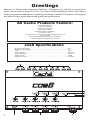
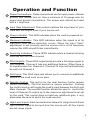
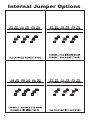
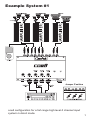
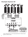
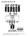
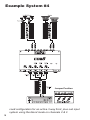
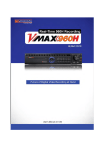
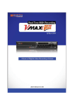
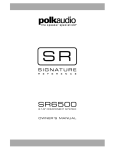
8 CHANNEL LINE OUTPUT CONVERTER
OWNERS MANUAL
Greetings
Welcome to Caché Audio Integration Solutions. We believe you will find our products to
be as easy to install as they are to use. Our unique OEM integration products offer today’s
audio enthusiasts an alternative to replacing their factory installed CD receiver or Navigation
unit and still enjoy world-class sound quality and performance.
All Caché Products Feature:
• Low Output Impedance
• High Input Impedance
• Flat Frequency Response
•High Output Voltages
•Excellent Signal To Noise Ratios
• Panel Mount RCA's
•Poly Caps And Low Tolerance Resistors In All Signal Path Circuits
• Power ON LED
• Removable Terminal Blocks For All Input Connections
• Proudly Designed And Engineered In The USA
2
coe8 Specifications
•Maximum Input Voltage......................................................................................................50 V
•Maximum Output Voltage...................................................................................................9 V
•THD....................................................................................................................................0.01% •Input Impedance................................................................................................................>20K ohms
•Output Impedance.............................................................................................................<50 ohms
•Signal to Noise...................................................................................................................>98dB
•Signal Sense Level............................................................................................................DC sense
Operation and Function
A Power Connections- These connections are for input power, chassis
ground, and remote turn-on. Use a minimum of 18 gauge wire for
power and ground connections. The power wire should be fused
with a 1 amp fuse.
B Input Gain Adjustment- This control matches the input level of your
coe8 with the output level of your source unit.
C Power Indicator- This LED indicates when the coe8 is powered on.
D Maximum Indicator- This LED indicates when the signal is at its
maximum level before distortion occurs. When the input "Gain"
adjustment is set correctly and the source unit is at its maximum
volume this LED should flicker intermittently.
E Summing Indicators- These LED's indicate when a channel is being
summed with the main channel.
F RCA Outputs- These RCA output jacks provide a full range signal to
your amplifier. Channel 4 has one additional feature. When there is
no signal present on Channel 4, Channel 3's input will automatically
be sent out Channel 4.
G AUX Input- This RCA input jack allows you to connect an additional
source to the coe8 such as an Ipod.
H Remote Control- This port is for the dual function Caché remote
control (Included). The first function is source selection. Pushing
the control knob in will toggle the coe8's input between the AUX and
Main channels. The second function allows the user to control the
level of Channel 4's output up to the maximum adjustment level set
on the coe8. This control does not add any additional gain, it only
attenuates the level at which the coe8 was set.
I High Level Inputs- Each terminal block allows for a high level left and
right channel signal to be input from the source unit. All four inputs
are full range inputs.
3
Installation Guidelines
INSTALLATION PRECAUTIONS
• Always mount the unit in a fashion so that it can be easily accessible for making adjustments.
• Avoid mounting the unit to subwoofer enclosures or high vibration areas.
• Do not cover the unit with carpet or any other material.
• Do not mount the unit in the engine compartment or anywhere that it will be subject to high temperatures, (ie, direct sunlight or heater) moisture, dust or dirt.
•Use rubber or plastic grommets to protect wires when routing them through metal.
•Always keep signal wires away from high current power wires.
•The ground connection should always be the first connection made.
WIRING INSTRUCTIONS
Ground Connection (GND)
The main ground connection should be made between the Gnd terminal on the unit
and a metal part of the vehicle close to the mounting location. This wire needs to be
as short as possible to minimize the possibility of induced noise. You should use 18
gauge wire or larger for the ground connection. The metal point on the vehicle where
the ground connection is made needs to have all paint removed and be scuffed down
to the bare metal. The ground wire should have a ring terminal soldered to it and be
bolted directly to the vehicle with the use of a star washer. Do not ground the unit near
existing (factory) ground points. These areas generally have multiple devices grounded to them and can cause induced noise.
Power Connection (+12V)
The main power connection should be made at the battery. This will ensure that the
unit receives the best possible connection to minimize noise. There must be an inline
fuse (1 amp) placed in series with the unit. The fuse should be within 18" of the battery. You should use 18 gauge wire or larger for the power connection. The power
wire should have a ring terminal soldered to it and be bolted to the vehicles battery. Do
not install the fuse in the holder until all the systems connections have been made.
Remote In
This Caché unit is turned on by applying +12 VDC to the remote turn-on terminal. This
terminal should be connected to the remote lead from the car stereo. This remote
lead from the source unit will trigger a +12V output only when the car stereo is turned
on. If the source unit does not provide a remote turn on you can use the accessory
terminal in the cars fuse block. This will however turn the unit on and off with the key,
regardless of whether the source unit is on or off.
Remote Out
This Caché unit is equipped with a signal sensing circuit that can detect a signal on
its input and provide a +12V output signal to turn on an aftermarket amplifier. Connect
this to the remote terminal on an aftermarket amplifier.
4
Internal Jumper Options
Blend
Blend
Blend
B
Direct
Direct
Direct
200Ω
ISO
GND
A
* coe8 shown with top cover removed.
A Isolation Jumpers- This jumper provides three different ground isolation
options for the input of the coe8. The three input options include GND,
Isolation, and 200ohms. Make sure the coe6 is turned off before making
your selection.
B Blending Jumpers- These jumpers are used to select either a Direct
(separate) or a Blended (summed) output. In the direct position the signal
on an individual channels input will come out the same channels output. In
the blended position the signals on two or more channels can be combined
with Channel 1 to provide one full range output. All of the channels that have
been selected to have their inputs blended will be combined and output onto
Channel 1. Each of the remaining channels being blended (2, 3, & 4) will
have the same signal on their channels output as what is on their input (not
a full range output like Channel 1).
5
Internal Jumper Options
6
Example System #1
Jumper Position
coe8 configuration for a full range high level 6 channel input
system in direct mode.
7
Example System #2
Jumper Position
coe8 configuration for a full range high level 4 channel input
system in direct mode.
8
Example System #3
Front High/
M id Spea
kers
Rear High/
M id Spea
kers
Subw oofers
Crossover
Blended Output
Front T
w eeter
Input
FrontM id
Input
Rear
Full
Range
Input
Subw oofer
Input
Factory Installed
Amplifier
Jumper Position
Data Bus
Cable
CHANNEL 2 IN BLEND MODE
CHANNEL 3 & 4 IN DIRECT MODE
coe8 configuration for an active 2 way front, plus rear input
system using the blend mode on channel 2.
9
Example System #4
Jumper Position
coe8 configuration for an active 3 way front, plus sub input
system using the blend mode on channels 2 & 3.
10
Caché Warranty
Caché warrants this product to be free from defects in material and workmanship for a period of one (1) year from the original date of purchase
provided it was purchased from an authorized Caché retailer within the
United States.
This warranty is valid only to the original purchaser and is not extended to
owners of the product subsequent to the original purchaser. Any applicable
implied warranties are limited in duration to a period of the express warranty
as provided herein beginning with the date of the original purchase at retail,
and no warranties, whether expressed implied, shall apply to this product
there after. Some states do not allow limitations on implied warranties;
therefore these exclusions may not apply to you.
This warranty gives you specific legal rights; however you may have other
rights that vary from state to state. If your Caché device needs service,
defective merchandise must be returned to your local Authorized Caché
dealer for warranty. Non-defective items received will be returned freight
collect. Freight damage and returns are not covered under warranty. Include
proof-of-purchase. Warranty expiration on items returned without proofof-purchase will be determined from the manufacturing date code. Any
questions can be directed to the Warranty Department at (480) 305-8999.
This warranty is valid only if the product is used for the purpose for which
it was designed. This warranty does not cover:
The cost of shipping this product to the Caché Service Department
Damage through negligence, misuse, abuse or accident
Damage caused by exposure to water and/or excessive heat
Items scratched, dented, or physically damaged due to abuse
Items returned from unauthorized individuals or dealers
Items previously repaired by any unauthorized repair facility
International customers: please contact your International Caché dealer
or distributor concerning specific procedures for your country’s warranty
policies. If you are not able to locate your local distributor, please contact
Caché for assistance at +1(480) 305-8999.
Specifications subject to change without notice.
11
6915 W Frye Rd
Chandler, AZ 85233
480 305 8999
480 813 6210 Fax
www.cacheaudio.com