1
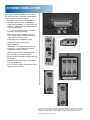
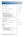
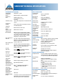
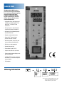
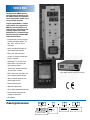
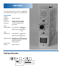
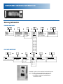
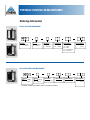
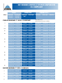
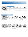
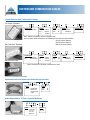
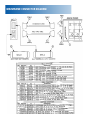
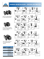
Modular
HOT RUNNER
CONTROLS
athenacontrols.com
ATHENA CONTROLS, INC.
5145 Campus Drive
Plymouth Meeting, PA 19462-1129
U.S.A.
HOT RUNNER CONTROL SYSTEMS
Athena has achieved its reputation as the leader in
the field of “hot runner” temperature control through
a series of firsts in the plastics industry:
• Microprocessor-based self-tuning temperature
controllers, from basic units to sophisticated
modules featuring Modbus ® communications and
ZonePilotTM software for remote configuration via
a Palm® handheld device
• 1-, 2-, and 3-zone portable models and modular
mainframe systems up to 48 zones
• Wide range of cables, connectors, and accessories, including cables compatible with Incoe®
and Fast Heat ® hot runner systems
• Compu-Step® heater conditioning system
• Compu-Cycle® power control system
• Built-in diagnostics
• SafeChangeTM “hot swap” feature provides safe
disconnect in case of inadvertent removal of
module from energized mainframe
• Automatic power hold if thermocouple breaks
• Self-regulating manual power controllers
• Mainframes field-convertible to global power supply voltages
• ZonePilotTM software for remote configuration via
Palm® handheld devices
• Series K control computers for hot runner control
applications up to 264 zones
Incoe, Fast Heat, ITC, MCS, and Palm are registered trademarks of their respective companies.
Modbus is a registered trademark of Schneider Automation. Athena, Compu-Step, Compu-Cycle,
ZonePilot, and SafeChange are registered trademarks or trademarks of Athena Controls, Inc.
© Copyright 2002, Athena Controls, Inc.
TABLE OF CONTENTS
Page
How to Order a Hot Runner System . . . . . . . . . . . . . . . . . . . . . . . . . . . . . . . . . . . . . .4
Series IMP Control Module . . . . . . . . . . . . . . . . . . . . . . . . . . . . . . . . . . . . . . . . . . . .6
Series RMB Control Module . . . . . . . . . . . . . . . . . . . . . . . . . . . . . . . . . . . . . . . . . . . .8
Series RMC Control Module . . . . . . . . . . . . . . . . . . . . . . . . . . . . . . . . . . . . . . . . . . . .10
Series SY Dual-Voltage System . . . . . . . . . . . . . . . . . . . . . . . . . . . . . . . . . . . . . . . . .12
Series SAM Standby Alarm Module . . . . . . . . . . . . . . . . . . . . . . . . . . . . . . . . . . . . .14
Mainframe Configurations . . . . . . . . . . . . . . . . . . . . . . . . . . . . . . . . . . . . . . . . . . . . . .15
Mainframe Ordering Information . . . . . . . . . . . . . . . . . . . . . . . . . . . . . . . . . . . . . . . .16
Tri-Zone Controller Mainframe . . . . . . . . . . . . . . . . . . . . . . . . . . . . . . . . . . . . . . . . .17
TM
Series IMP/P and RMC/P Portable Controllers . . . . . . . . . . . . . . . . . . . . . . . . . . . . .18
Portable Controller Mainframes . . . . . . . . . . . . . . . . . . . . . . . . . . . . . . . . . . . . . . . . .19
Hot Runner System Components . . . . . . . . . . . . . . . . . . . . . . . . . . . . . . . . . . . . . . . . .20
Power and Thermocouple Cables . . . . . . . . . . . . . . . . . . . . . . . . . . . . . . . . . . . . . . . .22
Custom and Combination Cables . . . . . . . . . . . . . . . . . . . . . . . . . . . . . . . . . . . . . . . . .23
Thermocouple and Mold Power Connectors . . . . . . . . . . . . . . . . . . . . . . . . . . . . . . .24
Connectors for Portable Systems . . . . . . . . . . . . . . . . . . . . . . . . . . . . . . . . . . . . . . . .25
Mainframe Connector Diagram . . . . . . . . . . . . . . . . . . . . . . . . . . . . . . . . . . . . . . . . . .26
Terminal Mounting Boxes . . . . . . . . . . . . . . . . . . . . . . . . . . . . . . . . . . . . . . . . . . . . . .27
Hot Runner System Accessories . . . . . . . . . . . . . . . . . . . . . . . . . . . . . . . . . . . . . . . . .28
HOW TO ORDER A HOT RUNNER CONTROL SYSTEM
ORDERING SPECIFICATIONS
1. Specify type of controller required.
IMP, RMB, or RMC
2. Amperage required per zone? (heater wattage x voltage)
15 or 30 amp
3. How many zones of control are required?
Up to 48 zones
4. Specify the mainframe cabinet.
• Size frame required is the number of control modules
plus any accessory modules.
• If 15 amp modules are used, specify MFL style frame.
• If 30 amp modules are used, specify MFH style frame.
• If an accessory module or Series RMC controller is used,
specify an MFL-C or MFH-C style frame.
• If a current/voltage monitor is required, specify CV suffix
in mainframe ordering code. (IMP only; not applicable to RMB or RMC)
See page 15
Note: Contact factory for combination mainframes
(15 A and 30 A together).
5. Specify Accessory Modules.
• IMP modules can be used with a Standby Alarm Module (SAM)
(Refer to page 14.
SAM
6. Specify cables, connectors, and terminal mounting boxes.
See pages 22 to 27
7. Choose optional mainframe accessories:
Floor stands
Transformer kits
Closure panels
See page 28
Notes: Athena’s mainframes are compatible with all
D-M-E Company’s G SERIES and SMART SERIES ®, ITC, MCS, Yudo ®,
and Incoe® brand mainframes.
Use ”D” ordering suffix for 60 Hz and °F
Use “X” ordering suffix for 50 Hz and °C
Use “E” ordering suffix for 50 Hz and °C, CE-compliant
G SERIES and SMART SERIES are trademarks of D-M-E Company; YUDO is a
trademark of Yudo Co., Ltd.; INCOE is a trademark of Incoe Corp.
NOTES
SERIES IMP
Athena’s Series IMP Modules use
microprocessor-based circuitry to
perform all required control functions.
Units have built-in diagnostics and
are fully self-tuning– setpoint temperatures are maintained without the
need to manually preset or adjust the
control temperature.
• Simultaneous digital setpoint and digital
temperature indication
• Available in 15-amp modules as well as
single-zone 15- and 30-amp portable
temperature controllers
• Compatible with all D-M-E Company’s
G SERIES and SMART SERIES®, ITC,
MCS, Yudo®, and Incoe® brand
mainframes.
• Compu-Step® feature removes moisture
from the heater before full power is
applied
• Compu-Cycle® feature improves
response time, reduces thermal fatigue
and prolongs heater life by applying AC
power smoothly and continuously
• Manual control for non-thermocouple
applications, provides standby or
“weekend” heat or to manually control
temperature if a thermocouple fails
• Diagnostic and protection features
include power “on,” power to load,
manual made, and over/under temperature, plus indicators and system protection for reversed and open thermocouples
• SafeChangeTM circuit “hot swap”
feature allows safe removal and
replacement of module
• Available standby heat and alarm
accessory module (SAM) automatically
sets all zones for standby, or “weekend” heat, and provides visual and
audible alarms for over/under temperature (see page 14).
Now...with
SafeChangeTM
Circuit Hot
Swap
Feature!
Series IMP/P Portable Single-Zone Controller
Ordering Information
I MP
Or
I M P
P
Single-Zone Portable
Market
D = Domestic
X = Export
E = CE
Current Rating
15 = 15 A
30 = 30 A (IMP
only)
Special Options
000 = Consult factory
Note: The 30 amp Series IMPis twice as wide
as the 15 amp model and has a circuit
breaker instead of a power switch.
SERIES IMP TECHNICAL SPECIFICATIONS
PERFORMANCE SPECIFICATIONS
Control Mode
CompuCycle® system
Temperature
Range
Ambient to 999˚F, or ambient to 535˚C
Temperature
Reset
Automatically corrects
reset to within 2˚F (1˚C) at
all settings
±1.0˚F (± 0.5˚C) dependent on the total thermal
Control Accuracy
system
Temperature
± 0.5% of full scale over the ambient range of
Stability
32 to 140˚F (0 to 60˚C)
Calibration
Accuracy
Better than 0.2% of full scale
Power
Response Time
Better than 0.13 seconds
Compensated
Manual Mode
Maintains constant output power to within
1% of manually set power level with line voltage variation from 192 to 264 volts. Power
control range is from 0 to 100%, using the
CompuCycle system power drive.
Over Temperature
Indicator
The upper segment of the leftmost display
will be “on” and the whole display flashes at
about 2 Hz when the temperature er ror
exceeds +30˚F (+17˚C)
Under Temperature
Indicator
The lower segment of the leftmost display
will be “on” and the whole display flashes at
about 2 Hz when the temperature error
exceeds -30˚F (-17˚C)
TC Break
Indication
Flashing
on the leftmost display (in
closed-loop and CompuStep)
TC Reverse
Indication
Flashing “
” on the leftmost display (in
closed-loop and CompuStep)
No Heat/Open Heater
Indication
Flashing “
” center segment only of the
leftmost display (in closed-loop)
CompuStep®
System
Control Mode
Variable stepping voltage, phase fired
CompuStep
System Duration
Approximately 5 minutes
CompuStep System
Output Voltage
Steps approximately from 25 V RMS to
170 VRMS with 240 Vac line input
CompuStep
System Holding
Temperature
256˚F (125˚C)
CompuStep
System Override
Temperature
200˚F (93˚C)
Operational Mode
Priority
a. TC break, TC reverse and No Heat override
CompuStep System b. Manual mode overrides TC break, TC reverse and No Heat
INPUT SPECIFICATIONS
Thermocouple
(T/C) Sensor
Type “J”, grounded or
ungrounded
External (T/C)
Resistance
Greater than 1000 ohms
T/C Isolation
Isolated from ground and
supply voltages
Cold Junction
Compensation
Automatic, better than 0.02˚F/
˚F (0.01˚C/˚C)
Input Type
Potentiometric
Input Impedance
22 megohms
Input Protection
Diode clamp, RC filter
Input Amplifier
Stability
Better than 0.05˚F/˚F (0.03˚C/˚C)
Input Dynamic
Range
Greater than 1000˚F (535˚C)
Common Mode
Rejection Ratio
Greater than 100 dB
Power Supply
Rejection Ratio
Greater than 90 dB
OUTPUT SPECIFICATIONS
Voltages
240 Vac nominal, single phase 120 Vac available
Power Capability
15 amperes, 3600 watts @ 240 Vac, 30
amperes, 7200 watts @ 240 Vac
Output Switch
Internal solid state triac,
triggered by ac zero crossing pulses
Overload
Protection
Triac and load use high speed fuses. Both
sides of ac line are fused.
Power Line
Isolation
Optically and transformer
isolated from ac lines. Isolation voltage is
greater than 2500 volts.
CONTROLS AND INDICATORS
Setpoint Control
Precision 3 digit pushbutton switch, direct
reading; Range: 0 to 999˚F (535˚C); Resolution:
1˚F (1˚C); Accuracy: Better than 0.5˚F (0.3˚C)
Manual Power
Control
Single turn potentiometer,
calibrated scale; Range: 0-100%; Linearity:
10%
Mode Control
3-position sliding switch selects mode of
operation
1. top position-Manual mode
2. middle position-Auto mode
3. bottom position-Auto mode with CompuStep system
Power ON/OFF
Rocker switch, UL, CSA, VDE approved
ELECTRICAL POWER SPECIFICATIONS
Input Voltage
240/120 Vac, + 10% -20%
Frequency
50 Hz ± 3 Hz, 60 Hz ± 3 Hz
DC Power Supplies Internal generated, regulated and temperature compensated
Module Power
Usage
Less than 3 watts, excluding load
SERIES RMB
The Athena Series RMB is a microprocessor-based, single-zone temperature controller specifically designed for
runnerless molding applications.
It features an easy-to-use operator
keypad, two LED displays, and three
discrete indicators for heat-current,
alarm and manual mode.
• Compatible with all D-M-E Company’s
G SERIES and SMART SERIES®, ITC,
MCS, Yudo®, and Incoe® brand
mainframes.
• Accepts Type J or Type K thermocouple input (jumper selectable)
• Auto-tuning, with adjustable proportional band and rate
• Bumpless auto/manual transfer
• Compu-Step® bakeout feature
prevents moisture at startup
• Built-in loop break, short, open, and
reverse thermocouple protection
• Built-in triac safety protection
• Ground-fault protection
• Preset alarms at 30° F (17°C)
• Jumper-selectable soft-start mode
• Current monitor feature displays average current to load
• SafeChangeTM circuit “hot swap” feature allows safe removal and replacement of module
• CE-compliant
Ordering Information
R M B
Market
D = Domestic
X = Export
E = CE
Current Rating
15 = 15 A
30 = 30 A
Special Options
000 = Consult factory
Note: The 30 amp Series RMB is twice as wide
as the 15 amp model and has a circuit
breaker instead of a power switch.
SERIES RMB TECHNICAL SPECIFICATIONS
PERFORMANCE SPECIFICATIONS
Auto Control Mode
Compu-Cycle® system
± 0.1˚F (± 0.1˚C) dependent on
Control Accuracy
the total thermal system
Temperature
Range
32 to 999˚F (0 to 537˚C)
Temperature
± 0.5% of full scale over the ambient
Stability
range of 32 to 131˚F (0 to 55˚C)
Calibration
Accuracy
Better than 0.2% of full scale
Power
Response Time
Better than 300 milliseconds
Process Sampling
100 milliseconds (nominal)
˚F/˚C
Jumper-selectable
Compu-Step®
System Control
Mode
Variable stepping voltage,
phase fired
Compu-Step
System Duration
Approximately 5 minutes
CompuStep System
Output Voltage
Steps approximately from 25 V RMS
with 240 Vac line output, phase-fired
Compu-Step
System
Override Temp
200˚F (93˚C)
Operational
Mode Priority
a. TC open, TC reverse, Shutdown and
Open heater override CompuStep
system
b. Manual mode overrides TC open,
TC reverse
INPUT SPECIFICATIONS
Thermocouple
(T/C) Sensor
Type “J” or Type “K”, grounded or
ungrounded (switch-selectable)
External
T/C Resistance
Maximum 100 ohms for rated
accuracy
T/C Isolation
Isolated from ground and
supply voltages
Cold Junction
Compensation
Automatic, better than
0.02˚F/˚F (0.01˚C/˚C)
Input Type
Potentiometric
Input Impedance
10 megohms
Input Protection
Diode clamp, RC filter
Input Amplifier
Stability
Better than 0.05 ˚F/˚F
(0.03˚C/˚C)
Input
Dynamic Range
Greater than 999˚F (537˚C)
Common Mode
Rejection Ratio
Greater than 100 dB
Power Supply
Rejection Ratio
Greater than 70 dB
OUTPUT SPECIFICATIONS
Voltages
Power Capability
Overload
Protection
Power Line
Isolation
240 Vac nominal, single
phase 120 Vac available
15 amperes, 3600 watts @240
Vac; 30 amperes, 7200 watts
@240 Vac
Triac and load use high speed fuses.
Both sides are fused (GBB)
Optically and transformer isolated from
ac lines. Isolation voltage is greater than
2500 volts.
Output Drive
Internal solid state triac,
triggered by ac zero crossing pulses
CONTROLS AND INDICATORS
Setpoint Control
Two buttons up or down.
Resolution: 1˚F (1˚C)
% Power Control
Two buttons up or down
Mode Control
Push button switch with LED indicator
for manual mode
Display
Top: 3 -digit filtered LED
Bottom: 4-digit filtered LED
Status Indicators
Heat-current output
Alarm
Power On-Off
Rocker Switch, UL, CSA, and VDE
approved
ELECTRICAL POWER SPECIFICATIONS
Input Voltage
240/120 Vac, + 10% - 20%
Frequency
50 Hz ± 3 Hz, 60 Hz ± 3 Hz
DC Power Supplies Internal generated, regulated and tempera ture compensated
Module Power
Usage
Less than 3 watts, excluding load
SERIES RMC
The Athena Series RMC brings new
and highly productive benefits to injection molders looking for a modular hot
runner controller that’s flexible, easy to
set up, and simple to operate.
Using the popular Modbus® communications protocol, the next-generation
RMC gives users the ability to set or
change all zones, either remotely from
a desktop computer, from a Palm®
handheld device, or (with the ALL command) from any other individual RMC
module in the mainframe.
• Compatible with all D-M-E Company’s
G SERIES and SMART SERIES®, ITC,
MCS, Yudo®, and Incoe® brand
mainframes.
• Choice of three default modes for
open thermocouple condition
• Built-in triac safety protection
• Accepts J or K thermocouple input
(jumper selectable)
• SafeChangeTM circuit “hot swap”
feature allows safe removal and
replacement of module
• Compu-Step® bakeout feature prevents moisture at startup
Series RMC/P Portable Single-Zone Controller
• Built-in loop break, short, open, and
reverse thermocouple protection
• “Boost” mode for temporary % of
power output increase
• Ground-fault protection
• Adjustable setpoint limits
• Stores highest temperature detected
Palm® Pilot with ZonePilot TM software
• Current monitor feature displays
average current to load
• CE-compliant
Ordering Information
R M C
Or
R M C
P
Single-Zone Portable
Market
D = Domestic
X = Export
E = CE
Current Rating
15 = 15 A
Special Options
000 = Consult factory
SERIES RMC TECHNICAL SPECIFICATIONS
PERFORMANCE SPECIFICATIONS
Auto Control Mode
CompuCycle® system
± 0.1˚F (±0.1˚C) dependent on
Control Accuracy
the total thermal system
Temperature
Range
32 to 999˚F (0 to 537˚C)
Temperature
±0.5% of full scale over the ambient
Stability
range of 32 to 131˚F (0 to 55˚C)
Calibration
Accuracy
Better than 0.2% of full scale
Power
Response Time
Better than 300 milliseconds
Process Sampling
100 milliseconds (nominal)
˚F/˚C
Jumper-selectable
Compu-Step®
System Control
Mode
Variable stepping voltage,
phase fired
Compu-Step
System Duration
Approximately 5 minutes
Compu-Step System
Output Voltage
Steps approximately from 25 V RMS
with 240 Vac line output, phase-fired
Compu-Step
System
Override Temp
200˚F (93˚C)
Operational
Mode Priority
a. TC open, TC reverse, Shutdown and
Open heater override CompuStep
system
b. Manual mode overrides TC open,
TC reverse
INPUT SPECIFICATIONS
Thermocouple
(T/C) Sensor
Type “J” or Type “K”, grounded or
ungrounded (switch-selectable)
External
T/C Resistance
Maximum 100 ohms for rated
accuracy
T/C Isolation
Isolated from ground and
supply voltages
Cold Junction
Compensation
Automatic, better than
0.02˚F/˚F (0.01˚C/˚C)
Input Type
Potentiometric
Input Impedance
10 megohms
Input Protection
Diode clamp, RC filter
Input Amplifier
Stability
Better than 0.05 ˚F/˚F
(0.03˚C/˚C)
Input
Dynamic Range
Greater than 999˚F (537˚C)
Common Mode
Rejection Ratio
Greater than 100 dB
Power Supply
Rejection Ratio
Greater than 70 dB
OUTPUT SPECIFICATIONS
Voltages
Power Capability
Overload
Protection
Power Line
Isolation
240 Vac nominal, single
phase 120 Vac available
15 amperes, 3600 watts @240 Vac
Triac and load use high speed fuses.
Both sides are fused (GBB)
Optically and transformer isolated from
ac lines. Isolation voltage is greater than
2500 volts.
Output Drive
Internal solid state triac,
triggered by ac zero crossing pulses
CONTROLS AND INDICATORS
Setpoint Control
Two buttons up or down.
Resolution: 1˚F (1˚C)
% Power Control
Two buttons up or down
Mode Control
Push button switch with LED indicator
for manual mode
Display
Top: 3 -digit filtered LED
Bottom: 4-digit filtered LED
Status Indicators
Heat-current output
Alarm
Power On-Off
Rocker Switch, UL, CSA, and VDE
approved
ELECTRICAL POWER SPECIFICATIONS
Input Voltage
115 to 230 Vac, ± 10%
Frequency
50-60 Hz
DC Power Supplies
Internally generated, regulated and
temperature compensated
Module
Power Usage
Less than 6 watts, excluding
load
SERIES SY
Athena’s low-voltage hot runner temperature control systems combine 240
Vac and 24 Vac into one unit and are
available in either Series RMB or
Series RMC control module configurations. A special safety interlock
prevents insertion of a 24 Vac control
module into a 240 Vac mainframe.
Both controllers share these
advanced features:
• Dual digital displays
• Auto-tuning, with adjustable
proportional band and rate
• Advanced diagnostics automatically
inform the user of fault conditions,
including open thermocouple,
shorted thermocouple, reversed
thermocouple, open heater, and high
and low process temperature.
• Compu-Step® provides gradual
phase angle-fired voltage
during warmup.
• Compu-Cycle® utilizes zero
crossover power to improve
response time, reduce thermal
fatigue, and prolong heater life.
System Configuration
Athena® low-voltage hot runner control systems include the
mainframe cabinet with fused circuit breaker/disconnect,
stepdown transformer, and floorstand. Controller modules,
mold connectors, terminal boxes, and combination cables
must be ordered separately (see ordering information below).
• Bumpless auto/manual
transfer
• Wide range of accessories and
control modules available to
customize system
Ordering Information
SY
Low-Voltage
System
Communications
0 = No
C = Yes (RMC
only)
Market
D = Domestic
X = Export
E = CE
240 Vac Zones
04 = 4 Zones
24 Vac Zones
04 = 4 Zones
08 = 8 Zones
CV Monitor
00 = No
CV = Yes
Mold Connectors:
Control
Module
024
Controller
RMC = Series RMC
RMB = Series RMB
Market
D = Domestic
X = Export
E = CE
Current Rating
15 = 15 amp
24 Vac Option
Special Options
(Consult Factory)
TPC-00-01
Terminal Boxes: PTC-00-TB-12
Combination Cables:
CPT-10 (10’)
CPT-20 (20’)
SERIES SY DUAL-VOLTAGE HOT RUNNER SYSTEM
The Athena Series RMB controller
features an easy-to-use operator
keypad, two LED displays, and
three discrete indicators for heatcurrent, alarm and manual mode.
• Accepts Type J or Type K thermocouple input (jumper selectable)
• Built-in loop break, short, open,
and reverse thermocouple protection
• Built-in triac safety protection
• Ground-fault protection
• Preset alarms at 30° F (17°C)
• Jumper-selectable soft-start
mode
• Current monitor feature displays
average current to load
See page 8 for more information.
The Athena Series RMC controller
offers the same features as the
Series RMB PLUS:
• Built-in current monitoring
• Front-panel boost function
• ALL command
• Remote communications via
Modbus or Palm handheld device
• Choice of three default modes for
open thermocouple protection
• Boost mode for temporary % of
power output increase
See page 10 for more information.
SAM SERIES
Over/under temperature alarm. Built in standby/night
heat. Audio and relay output. For use with IMP only.
SPECIFICATIONS
Standby
Temperature
AC Input
Requirements
Alarm Limits
Alarm
Output (Audible)
240 Vac + 10% -20%, 48-63 Hz
(standard) 120 Vac (Available)
+/- 30° F (17° C) when used
with an IMP
Over Temperature: 2 KHz tone at
2 Hz interval
Under Temperature:1 Hz flashing
interval
Alarm
Output (Visual)
Output Connector
Communication
Capacity
200 deg F (93 deg C)
Over Temperature: 2 Hz flashing
rate
Under Temperature:1 Hz flashing
rate
AMP MIL-style connector (4 Pin) providing Normally Closed and Normally
Opened relay contacts.
(5 amp maximum)
50 zones maximum
Ordering Information
S A M
Market
D = Domestic
X = Export
Special Options
000 = Consult factory
MAINFRAME CONFIGURATIONS
Dimensions*
MFL
Mainframe
MAINFRAMES FOR 15-AMP MODULES*
The configurations illustrated below provide a wide selection of zone capacities
to suit almost any control application. The 5, 8 and 12 zone frames use individual
frame sections. The 16 thru 48 zone frames use 2, 3 or 4 frame sections rigidly fastened together into one prewired integral unit which requires only one main AC
power input connection. The Current/ Voltage Monitor option will be factory
installed and must be ordered at same time as mainframe.
1- & 2-zone
3-zone
5-zone
8-zone
12-zone
Height
Depth
Width
9-1/4”
9-1/4”
8-7/8”
8-7/8”
8-7/8”
10”
12-3/4”
11-1/2”
11-1/2”
11-1/2”
7”
7”
16-1/8”
22-1/8”
30-1/4”
MFH
Mainframe
1-zone
2-zone
3-zone
5- & 6-zone
*For mainframes over 12 zones,
add dimensions of stacked cabinets.
1-Zone
2-Zone
11-Zone
3-Zone
12-Zone
8-Zone
5-Zone
16-Zone
20-Zone
24-Zone
28-Zone
32-Zone
40-Zone
44-Zone
48-Zone
36-Zone
MAINFRAMES FOR 30-AMP MODULES*
The 5 configurations illustrated below provide 1, 2, 3, 5 or 6 zones of 30 amp control for higher wattage
heater applications. The Current/Voltage Monitor option will be factory installed and must be ordered at
same time as mainframes.
1-Zone
2-Zone
3-Zone
5-Zone
6-Zone
*NOTE: Blank panel(s) should be ordered to provide for heat dissipation and to cover unused zones in frames. Combination frames to accommodate both 15 and
30 amp modules are available on special order.
15
MAINFRAME ORDERING INFORMATION
Ordering Information
STANDARD MAINFRAMES
Base
MFL = 15 A zones
Communications
O = No comms.
C = Comms.
Market
D = Domestic
X = Export
E = CE
HIGH-POWER MAINFRAMES
Base
MFH =30 A zones
Communications
O = No comms.
C = Comms.
Market
D = Domestic
X = Export
E = CE
Zone
Count
05 = 5
08 = 8
11 = 11
12 = 12
16 = 16
20 = 20
24 = 24
28 = 28
32 = 32
36 = 36
40 = 40
44 = 44
48 = 48
Zone
Count
02 = 2
03 = 3
05 = 5
06 = 6
CV Monitor
OO = Not included
CV = Included
CV Monitor
OO = Not included
CV = Included
Special Options
000 = Consult factory
Special Options
000 = Consult factory
Available in place of the standard breaker/disconnect
panel, the CV monitor provides the operator with:
• voltage information from each phase
• the ability to select an individual zone
to monitor current
TRI-ZONETM CONTROLLER MAINFRAME
Ordering Information
0 3
Base
MFL
Communications
0 = No
1 = Yes
Market
D = Domestic
X = Export
Combo Cable for Tri-ZoneTM Controller Mainframe
T P T C
Cable
TPTC = Output Cable
for Tri-ZoneTM
Controller
Mainframe
Length
10 = 10’
20 = 20’
Individual Zone Cable (3 Required)
M P T C
Individual-Zone, 5-Pin
MPTC = 5-Pin Cable
(3 required)
for Tri-ZoneTM
Controller
Mainframe
Length
10 = 10’
20 = 20’
Combo Connector for Tri-ZoneTM Controller Mainframe
T P T 0 3
Connector
TPT03 = Output Connector for Tri-ZoneTM
Controller
Mainframe
Market
A = Domestic
and Export
E = CE
Zones
Input
CO = Clamp
NO = NEMA
Output
PT = Combo
PO = 5-Pin/Fan
SERIES IMP/P AND RMC/P PORTABLE CONTROLLERS
SERIES IMP/P SINGLE-ZONE CONTROLLER
SERIES RMC/P SINGLE-ZONE CONTROLLER
Note: For features and technical specifications of
the Series RMC/P, refer to the Series RMC
description on page 10.
Note: For features and technical specifications of
the Series IMP/P, refer to the Series IMP
description on page 6.
IMP/P15B
NEMA in,
5-Pin out
IMP/P15A
NEMA in,
NEMA out
IMP/P10B
Line in,
5-Pin out
AC INPUT
OUTPUT
AC INPUT
OUTPUT
AC INPUT
THERMOCOUPLE
INPUT
OUTPUT
5-PIN CONNECTOR
WIRING
Ordering Information
Controller
IMP/P = IMPP
RMC/P = RMBP
Connector Style
10A = NEMA/NEMA
10B = Line In/5-Pin
15A = NEMA/NEMA
15B = NEMA /5-Pin
Market
D = Domestic
X = Export
E* =
CE
* 10 amp only
Special Options
000 = Consult
factory
PORTABLE CONTROLLER MAINFRAMES
Ordering Information
SINGLE / DUAL ZONE MAINFRAMES
MF L
Controller
MFL = 15 amp
Zones
Market
D = Domestic
X = Export
Zone Count
1 = Single Zone
2 = Dual Zone
Input (Power)
NO = NEMA
CO = Clamp
Output (Power)
NF = NEMA / Fan
CO = Clamp
PO = 5-Pin
PS = 5-Pin / Switch
PF = 5-Pin / Fan
Special Options
000 = Consult
factory
HIGH-POWER SINGLE ZONE MAINFRAMES
MF H
Controller
MFH = 30 amp
Zones
Market
D = Domestic
X = Export
Zone Count
1 = Single Zone
Input (Power)
CO= Clamp
* Controller modules not included; frame connections included.
Output (Power)
CO= Clamp
Special Options
000 = Consult
factory
HOT RUNNER CONTROLS, SYSTEM COMPONENTS
DOMESTIC AND EXPORT
CABLES
#Zones
Mold Power
(C10=10 Ft)
(C20=20 Ft)
Thermocouple
(C10=10 Ft)
(C20=20 Ft)
CONNECTORS
Mold Power
Input*
Thermocouple
STANDARD MAIN FRAME ( “A” SUFFIX = DOMESTIC OR
EXPORT)
TERMINAL BOXES **
Power Input
Thermocouple
Combination
* Includes Crimp Connectors
**Order Power Input and Thermocouple or Combination
5
1-MPCL05CxxA 1-TC05CxxA
1-PICL05A
1-MTC05A
1-PICL512TBA
1-MTC005TBA 1-PTCL005TBA
8
1-MPCL08CxxA 1-TC08CxxA
1-PICL08A
1-MTC08A
1-PICL512TBA
1-MTC008TBA 1-PTCL008TBA
11/12
1-MPCL12CxxA 1-TC12Cxx A
1-PICL12A
1-MTC12A
1-PICL512TBA
1-MTC012TBA 1-PTCL012TBA
16
2-MPCL08CxxA 2-TC08CxxA
2-PICL08A
2-MTC08A
2-PICL512TBA
2-MTC008TBA 1-PTCL016TBA
20
1-MPCL08CxxA 1-TC08CxxA
1-PICL08A
1-MTC08A
2-PICL512TBA
1-MTC008TBA 1-PTCL008TBA
1-MPCL12CxxA 1-TC12CxxA
1-PICL12A
1-MTC12A
24
2-MPCL12CxxA 2-TC12CxxA
2-PICL12A
2-MTC12A
2-PICL512TBA
2-MTC012TBA 1-PTCL024TBA
28
2-MPCL08CxxA 2-TC08CxxA
2-PICL08A
2-MTC08A
3-PICL512TBA
2-MTC008TBA 1-PTCL016TBA
1-MPCL12CxxA 1-TC12CxxA
1-PICL12A
1-MTC12A
1-MPCL08CxxA 1- TC08CxxA
1-PICL08A
1-MTC08A
2-MPCL12CxxA 2-TC12CxxA
2-PICL12A
2-MTC12A
36
3-MPCL12CxxA 3-TC12CxxA
3-PICL12A
3-MTC12A
3-PICL512TBA
3-MTC012TBA 3-PTCL012TBA
40
2-MPCL08CxxA 2-TC08CxxA
2-PICL08A
2-MTC08A
4-PICL512TBA
2-MTC008TBA 1-PTCL016TBA
2-MPCL12CxxA 2-TC12CxxA
2-PICL12A
2-MTC12A
1-MPCL08CxxA 1-TC08CxxA
1-PICL08A
1-MTC08A
3-MPCL12CxxA 3-TC12CxxA
3-PICL12A
3-MTC12A
4-MPCL12CxxA 4-TC12CxxA
4-PICL12A
4-MTC12A
32
44
48
1-MTC012TBA 1-PTCL012TBA
1-MTC012TBA 1-PTCL012TBA
3-PICL512TBA
1-MTC008TBA 1-PTCL008TBA
2-MTC012TBA 1-PTCL024TBA
2-MTC012TBA 1-PTCL024TBA
4-PICL512TBA
1-MTC008TBA 1-PTCL008TBA
3-MTC012TBA 3-PTCL012TBA
4-PICL512TBA
4-MTC012TBA 2-PTCL024TBA
HIGH POWER MAINFRAME (“A” SUFFIX = DOMESTIC OR EXPORT)
2
1-MPCH23CxxA 1-TC05CxxA
1-PICH23A
1-MTC05A
1-PICH023TBA
1-MTC005TBA 1-PTCH023TBA
3
1-MPCH23CxxA 1-TC05CxxA
1-PICH23A
1-MTC05A
1-PICH023TBA
1-MTC005TBA 1-PTCH023TBA
5
1-MPCH05CxxA 1-TC05CxxA
1-PICH05A
1-MTC05A
1-PICH005TBA
1-MTC005TBA 1-PTCH005TBA
6
1-MPCH06CxxA 1-TC08CxxA
1-PICH06A
1-MTC08A
1-PICH006TBA
1-MTC008TBA 1-PTCH006TBA
HOT RUNNER CONTROLS, SYSTEM COMPONENTS
CE- COMPLIANT
CABLES
#Zones
Mold Power
(C10=10 Ft)
(C20=20 Ft)
Thermocouple
(C10=10 Ft)
(C20=20 Ft)
CONNECTORS
Mold Power
Input*
Thermocouple
STANDARD MAINFRAME (“E” SUFFIX = CE-COMPLIANT)
TERMINAL BOXES * *
Power Input
Thermocouple
Combination
* Includes Crimp Connectors
**Order Power Input and Thermocouple or Combination
5
1-MPCL05CxxE
1-TC05CxxE
1-PICL05E
1-MTC05E
1-PICL005TBE
1-MTC005TBE 1-PTCL005TBE
8
1-MPCL08CxxE
1-TC08CxxE
1-PICL08E
1-MTC08E
1-PICL008TBE
1-MTC008TBE 1-PTCL008TBE
11/12
1-MPCL12CxxE
1-TC12CxxE
1-PICL12E
1-MTC12E
1-PICL012TBE
1-MTC012TBE 1-PTCL012TBE
16
2-MPCL08CxxE 2-TC08CxxE
2-PICL08E
2-MTC08E
2-PICL008TBE
2-MTC008TBE 1-PTCL016TBE
20
1-MPCL08CxxE
1-TC08CxxE
1-PICL08E
1-MTC08E
2-PICL008TBE
1-MTC008TBE 1-PTCL008TBE
1-MPCL12CxxE
1-TC12CxxE
1-PICL12E
1-MTC12E
24
2-MPCL12CxxE
2-TC12CxxE
2-PICL12E
2-MTC12E
2-PICL012TBE
2-MTC012TBE 1-PTCL024TBE
28
2-MPCL08CxxE 2-TC08CxxE
2-PICL08E
2-MTC08E
3-PICL008TBE
2-MTC008TBE 1-PTCL016TBE
1-MPCL12CxxE
1-TC12CxxE
1-PICL12E
1-MTC12E
1-MPCL08CxxE
1- TC08CxxE
1-PICL08E
1-MTC08E
2-MPCL12CxxE
2-TC12CxxE
2-PICL12E
2-MTC12E
36
3-MPCL12CxxE
3-TC12CxxE
3-PICL12E
3-MTC12E
3-PICL012TBE
3-MTC012TBE 3-PTCL012TBE
40
2-MPCL08CxxE
2-TC08CxxE
2-PICL08E
2-MTC08E
4-PICL008TBE
2-MTC008TBE 1-PTCL016TBE
2-MPCL12CxxE
2-TC12CxxE
2-PICL12E
2-MTC12E
1-MPCL08CxxE
1-TC08CxxE
1-PICL08E
1-MTC08E
3-MPCL12CxxE 3-TC12CxxE
3-PICL12E
3-MTC12E
4-MPCL12CxxE
4-PICL12E
4-MTC12E
32
44
48
4-TC12CxxE
1-MTC012TBE 1-PTCL012TBE
1-MTC012TBE 1-PTCL012TBE
3-PICL008TBE
1-MTC008TBE 1-PTCL008TBE
2-MTC012TBE 1-PTCL024TBE
2-MTC012TBE 1-PTCL024TBE
4-PICL008TBE
1-MTC008TBE 1-PTCL008TBE
3-MTC012TBE 3-TCL012TBE
4-PICL012TBE
4-MTC012TBE 2-PTCL024TBE
HIGH POWER MAINFRAME (“E” SUFFIX = CE-COMPLIANT)
2
1-MPCH23CxxE 1-TC05CxxE
1-PICH23E
1-MTC05E
1-PICH023TBE
1-MTC005TBE 1-PTCH023TBE
3
1-MPCH23CxxE 1-TC05CxxE
1-PICH23E
1-MTC05E
1-PICH023TBE
1-MTC005TBE 1-PTCH023TBE
5
1-MPCH05CxxE 1-TC05CxxE
1-PICH05E
1-MTC05E
1-PICH005TBE
1-MTC005TBE 1-PTCH005TBE
6
1-MPCH06CxxE 1-TC08CxxE
1-PICH06E
1-MTC08E
1-PICH006TBE
1-MTC008TBE 1-PTCH006TBE
POWER AND THERMOCOUPLE CABLE ORDERING INFORMATION
Mold Thermocouple Cable -- MFL and MFH Mainframes
Cable
TC =
Mold
thermocouple
cable
# Zones
05 =
5 Zones
08 =
8 Zones
12 =
12 Zones
Length*
C10 =
10’
C20 =
20’
Market
A = Domestic
and Export
E = CE
Special Options
000 = Consult
factory
Length*
C10 =
10’
C20 =
20’
Market
A = Domestic
and Export
E = CE
Special Options
000 = Consult
factory
Length*
C10 =
10’
C20 =
20’
Market
A = Domestic
and Export
E = CE
Special Options
000 = Consult
factory
Mold Power Cable (15 amp) - Used with MFL Mainframe
Cable
MPCL = Mold power
cable
# Zones
05 =
5 Zones
O8 =
8 Zones
12 =
12 Zones
High Power Mold Power Cable (30 amp) - Used with MFH Mainframe
Cable
MPCH = High power
mold power
cable
*Consult factory for special lengths.
# Zones
23 =
2 or 3
Zones
05 =
5 Zones
06 =
6 Zones
CUSTOM AND COMBINATION CABLES
Custom Cables for Incoe ® and Fast Heat® Systems
For Incoe® Systems
Custom Cable
CC =
Combination
For Fast Heat ® Systems
# Zones
04 =
4 Zones
08 =
8 Zones
12 =
12 Zones
Length
C10 =
C20 =
10’
20’
Market
A = Domestic
and Export
Configuration
002
Note: Athena connectors are on mainframe side.
On mold side, cable connects to the following Incoe connector part number:
#1614 (4-zone system)
#3214 (8-zone system)
#4814 (12-zone system)
Custom Cable
CM =
Mold Power
CT =
Thermocouple
CM Mold Power Cable
# Zones
05 =
5 Zones
09 =
9 Zones
12 =
12 Zones
Length
C10 =
C20 =
10’
20’
Note: Connects to Fast Heat connectors on mold.
CT Thermocouple Mold Power Cable
Combination Power and Thermocouple Cable (One zone per cable)
Cable
MPTC = Combination
power and
thermocouple
cable
Length*
C10 =
10’
C20 =
20’
Combo Output Cable for Tri-ZoneTM Controller Mainframe
T P T C
Cable
TPTC = Combo Cable
for Tri-Zone
Controller
Mainframe
Length*
10 = 10’
20 = 20’
Market
A = Domestic
and Export
Configuration
012
THERMOCOUPLE AND MOLD POWER CONNECTORS
THERMOCOUPLE CONNECTORS
Connector
MTC = Mold Thermocouple
Connector
# Zones
O5=
5 Zones
O8=
8 Zones
12 =
12 Zones
Market
A = Domestic
and Export
E = CE
MOLD POWER/INPUT CONNECTORS
Connector
PICL = Mold Power
Connector
Connector
PICH = High-Power
Mold Power
Connector
# Zones
O5 =
5 Zones
O8 = 8 Zones
12 = 12 Zones
# Zones
23 =
2 or 3 Zones
05 =
5 Zones
06 =
6 Zones
COMBO CONNECTORS FOR TRI-ZONE TM SYSTEM
T P T 0 3
Connector
TPT03 = Output Connector for Tri-Zone
System
Market
A = Domestic
and Export
E = CE
Market
A = Domestic
and Export
E = CE
Market
A = Domestic
and Export
E = CE
CONNECTORS AND CABLE FOR PORTABLE SYSTEMS
COMBINATION POWER AND THERMOCOUPLE CONNECTORS FOR SINGLE-, DUAL-, AND TRI-ZONE
(ONE PER ZONE)
OC1
M1
F1
IC1
C K P T
Individual-Zone
Combo Connectors
CKPT = 5-Pin Combo
Mold Power/
Thermocouple
Connectors for
Portable Mainframes
Type
OC1 = Frame
M1 = Cable, Frame-End
F1 = Cable, Mold-End
IC1 = Mold
OTHER CONNECTORS FOR PORTABLE SYSTEMS
215K005U01
(AC1512F)
Cord connector,
female
15 A, 125 V
Power out
215K002U01
(AC2024F)
Connector chassis,
female
20 A, 250 V
Power out
215K006U01
(AC1512M)
Cord connector,
male
15 A, 125 V
Power in
215K004U01
(AC1524F)
Cord connector,
female
15 A, 250 V
Power in
215K001U01
(AC2024M)
TCS1
Connector chassis, TC Socket,
male
mold side
20 A, 250 V
Power in
215K003U01
(AC1524M)
Cord connector,
male
15 A, 250 V
Power in
215P001U01
(M2MJ)
TC mini-plug
MAINFRAME CONNECTOR DIAGRAM
TERMINAL MOUNTING BOXES - ORDERING INFORMATION
Box
MTC = Thermocouple
Box
# Zones
005 = 5 Zones
008 = 8 Zones
012 = 12 Zones
Kit
TB = Terminal
Box
Market
A = Domestic
or Export
E = CE
MTC Terminal Mounting Boxes
for Thermocouple Connectors
Box
PICL = Power Box
(Domestic
and Export)
PICL and PICH Terminal Mounting Boxes for Mold Power Input
Connectors (15 amps)
PTCH and PTCL Combination
Terminal Mounting Boxes
(30 amps)
# Zones
512 = 5 Zones
512 = 8 Zones
512 = 12 Zones
Kit
TB = Terminal
Box
Market
A = Domestic
or Export
E = CE
Box
PICL = Power
Box
(CE only)
# Zones
005 = 5 Zones
008 = 8 Zones
012 = 12 Zones
Kit
TB = Terminal
Box
Market
E = CE
Box
PICH = High
Power
Box (30A)
# Zones
023 = 2 or 3 Zones
005 = 5 Zones
006 = 6 Zones
Kit
TB = Terminal
Box
Market
A = Domestic
or Export
E = CE
Box
PTCH = High Power
Combina tion
Box (30A)
# Zones
023 = 2 or 3 Zones
005 = 5 Zones
006 = 6 Zones
Kit
TB = Terminal
Box
Box
PTCL = Combination
Box (Domestic
and Export)
# Zones
005 = 5 Zones
008 = 8 Zones
012 = 12 Zones
Kit
TB = Terminal
Box
Market
A = Domestic
or Export
E = CE
BOXES FOR PORTABLE SYSTEMS
Model No.
PTCL-001-TB-A
Used With
PIM/PAM and MFL
mainframes with one
5-pin connector
PTCL-002-TB-A MFL mainframes
with two 5-pin
connectors
PTCH-001-TB-A MFH mainframes
with one 30-amp
NEMA plug and one
thermocouple plug
Market
A = Domestic
or Export
E = CE
HOT RUNNER SYSTEM ACCESSORIES
Ordering Information
TRANSFORMER KITS
Transformer kits are fully
wired and include enclosed
transformer (480 Vac 3ø in,
240 Vac 3ø out) with
adjustable voltage taps,
power cable to main frame,
disconnect switch, extra
fuses, and floor stand with
all hardware. Other transformers are available for
your particular power
requirements.
Transformer
TK= TK
Rating
O6 = 6 KVA
O9 = 9 KVA
15 = 15 KVA
30 = 30 KVA
45 = 45 KVA
Phases
1 = Single
Phase
3 = Three
Phase
Voltage
A= 480
B= 600
CLOSURE (BLANKING) PANELS
Must be used to cover
unused zones in main frames
for correct air circulation
(cooling). MFB10 for use on
single unused zones. MFB20
for use on two unused
zones. Supplied with pushpull panel fasteners.
Panel
MFB= Blank
Zones
10 =Single zone
20 =Dual Zone
Market
A = Domestic
and Export
E = CE
UNIVERSAL FLOOR STAND
Panel
MFS= Floorstand
MODULE REPLACEMENT FUSES
Catalog No.
Description Amps
Quantity
ABC15
15 amp, 240 V
15
5
A25X30
30 amp, 240 V
30
1
INSULATED CRIMP CONNECTORS
For easy splicing of mold power input
connector leads to heater leads.
Catalog Number
Amps
Quantity
HWCC-1
15
36
HWCC-2
30
20
Zones
5812 = Adjustable
Special Options
Consult Factory
NOTES
NOTES
NOTES
ALSO FROM ATHENA CONTROLS...
Series K Hot Runner Controls
Power Controls
Universal Digital Controllers
Power Handlers
Custom Control Solutions
Analog Controllers
VIntage Controllers
TudorTM Temperature Sensors
Athena Controls, Inc. • 5145 Campus Drive • Plymouth Meeting, PA 19462 • Toll-Free in U.S.: 800.782.6776
Tel: 610.828.2490 • Fax: 610.828.7084 • E-mail: [email protected] • Internet: athenacontrols.com