1
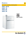
Modulens
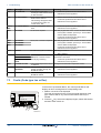
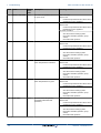
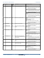
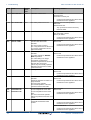
EN
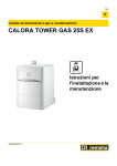
Gas fired floor-standing condensing boiler
AGC 10/15
AGC 15
AGC 25
AGC 35
User Guide
300026080-001-04
Contents
1
Safety instructions .....................................................................................4
1.1
Safety instructions ...............................................4
1.2
Recommendations ................................................5
1.3
Liabilities ...............................................................6
1.3.1
1.3.2
1.3.3
2
About this manual ......................................................................................8
2.1
Symbols used .......................................................8
2.1.1
2.1.2
2.2
3
4
Abbreviations ........................................................9
3.1
Certifications .......................................................10
3.2
Technical specifications ....................................10
Description ................................................................................................12
Operating principle .............................................12
4.1.1
4.1.2
Gas/air setting .......................................................12
Combustion ...........................................................12
4.2
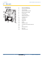
Main parts ............................................................13
4.3
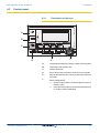
Control panel .......................................................14
4.3.1
4.3.2
4.3.3
Description of the keys ..........................................14
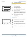
Description of the display ......................................15
Browsing in the menus ..........................................18
Operating the appliance ..........................................................................19
5.1
Putting the appliance into operation ................19
5.2
Reading out measured values ...........................19
5.3
Changing the settings ........................................21
5.3.1
5.3.2
5.3.3
5.3.4
1
Symbols used in the manual ...................................8
Symbols used on the equipment .............................8
Technical specifications ..........................................................................10
4.1
5
Manufacturer’s liability .............................................6
Installer’s liability .....................................................6
User’s liability ..........................................................7
Setting the set point temperatures ........................21
Selecting the operating mode ...............................22
Forcing domestic hot water production .................23
Setting the contrast and lighting on the
display ...................................................................23
18/12/2014 - 300026080-001-04
Contents
5.3.5
5.3.6
5.3.7
6
7
8
9
2
Setting the time and date ......................................24
Selecting a timer programme ................................24
Customising a timer programme ...........................25
5.4
Installation shutdown .........................................27
5.5
Antifreeze protection ..........................................27
Checking and maintenance .....................................................................29
6.1
General instructions ...........................................29
6.2
Periodic checks ..................................................29
Troubleshooting .......................................................................................31
7.1
Anti-hunting ........................................................31
7.2
Messages (Code type Bxx or Mxx) ....................31
7.3
Faults (Code type Lxx or Dxx) ...........................33
Energy savings .........................................................................................39
8.1
Energy-saving advice .........................................39
8.2
Recommendations ..............................................39
Warranty ....................................................................................................40
9.1
General ................................................................40
9.2
Warranty terms ...................................................40
18/12/2014 - 300026080-001-04
3
18/12/2014 - 300026080-001-04
AGC 10/15 AGC 15 AGC 25 AGC 35
1. Safety instructions
1
Safety instructions
1.1
Safety instructions
DANGER
This appliance can be used by children aged
from 8 years and above and persons with
reduced physical, sensory or mental capabilities
or lack of experience and knowledge if they have
been given supervision or instruction concerning
use of the appliance in a safe way and
understand the hazards involved. Children shall
not play with the appliance. Cleaning and user
maintenance shall not be made by children
without supervision.
DANGER
If you smell gas:
1.
2.
3.
4.
5.
Do not use a naked flame, do not smoke, do
not operate electrical contacts or switches
( doorbell, light, motor, lift, etc..).
Shut off the gas supply.
Open the windows.
Evacuate the premises.
Call your fitter.
DANGER
If you smell flue gases:
1.
2.
3.
4.
18/12/2014 - 300026080-001-04
Switch the appliance off.
Open the windows.
Evacuate the premises.
Call your fitter.
4
AGC 10/15 AGC 15 AGC 25 AGC 35
1. Safety instructions
WARNING
Depending on the settings of the appliance:
4 The temperature of the flue gas conduits
may exceed 60°C.
4 The temperature of the radiators may reach
85°C.
4 The temperature of the domestic hot water
may reach 65°C.
CAUTION
Do not neglect to service the appliance:
4 For completely safe and optimum operation,
you must have your boiler regularly serviced
by an approved installer.
1.2
Recommendations
WARNING
Only qualified professionals are authorised to
work on the appliance and the installation.
4 Regularly check the water pressure in the installation
(minimum pressure 0.8 bar, recommended pressure
between 0.8 and 1.5 bar).
4 Keep the appliance accessible at all times.
4 Never remove or cover labels and rating plates affixed
to the appliance. Labels and rating plates must be
legible throughout the entire lifetime of the appliance.
4 The appliance should be on Summer or Antrifreeze
mode rather than switched off to guarantee the
following functions:
- Anti blocking of pumps
- Antifreeze protection
5
18/12/2014 - 300026080-001-04
1. Safety instructions
AGC 10/15 AGC 15 AGC 25 AGC 35
1.3
Liabilities
1.3.1.
Manufacturer’s liability
Our products are manufactured in compliance with the
requirements of the various applicable European
Directives. They are therefore delivered with [ marking
and all relevant documentation.
In the interest of customers, we are continuously
endeavouring to make improvements in product quality.
All the specifications stated in this document are therefore
subject to change without notice.
Our liability as the manufacturer may not be invoked in the
following cases:
4 Failure to abide by the instructions on using the
appliance.
4 Faulty or insufficient maintenance of the appliance.
4 Failure to abide by the instructions on installing the
appliance.
1.3.2.
Installer’s liability
The installer is responsible for the installation and
commissioning of the appliance. The installer must
respect the following instructions:
4 Read and follow the instructions given in the manuals
provided with the appliance.
4 Carry out installation in compliance with the prevailing
legislation and standards.
4 Perform the initial start up and carry out any checks
necessary.
4 Explain the installation to the user.
4 If a maintenance is necessary, warn the user of the
obligation to check the appliance and maintain it in
good working order.
4 Give all the instruction manuals to the user.
18/12/2014 - 300026080-001-04
6
1. Safety instructions
AGC 10/15 AGC 15 AGC 25 AGC 35
1.3.3.
User’s liability
To guarantee optimum operation of the appliance, the
user must respect the following instructions:
4 Read and follow the instructions given in the manuals
provided with the appliance.
4 Call on qualified professionals to carry out installation
and initial start up.
4 Get your installer to explain your installation to you.
4 Ensure the Appliance is serviced in accordance with
the manufacturer’s instructions by a suitable qualified
person.
4 Keep the instruction manuals in good condition close
to the appliance.
7
18/12/2014 - 300026080-001-04
2. About this manual
AGC 10/15 AGC 15 AGC 25 AGC 35
2
About this manual
2.1
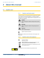
Symbols used
2.1.1.
Symbols used in the manual
In these instructions, various danger levels are employed to draw the
user’s attention to particular information. In so doing, we wish to
safeguard the user’s safety, highlight hazards and guarantee correct
operation of the appliance.
DANGER
Risk of a dangerous situation causing serious physical
injury.
WARNING
Risk of a dangerous situation causing slight physical
injury.
CAUTION
Risk of material damage.
Signals important information.
¼Signals a referral to other instructions or other pages in the
instructions.
2.1.2.
Symbols used on the equipment
4
Protective earthing
~
Alternating current
Before installing and commissioning the device, read
carefully the instruction manuals provided.
Dispose of the used products in an appropriate recovery
and recycling structure.
This appliance must be connected to the protective earth.
D000241-C
18/12/2014 - 300026080-001-04
8
2. About this manual
1
AGC 10/15 AGC 15 AGC 25 AGC 35
Caution: danger, live parts.
Disconnect the mains power prior to any operations.
2
M002628-A
2.2
Abbreviations
4 3CE: Collective conduit for sealed boiler
4 DHW: Domestic hot water
4 Interscenario switch: Home automation switch that can be used
to centralise and control several scenarios
4 Hi: Lower heating value LHV (Nett)
4 Hs: Higher heating value HHV (Gross)
4 PPS: Polypropylene hardly inflammable
4 PCU: Primary Control Unit - PCB for managing burner operation
4 PSU: Parameter Storage Unit - Parameter storage for PCBs
PCU and SU
4 SCU: Secondary Control Unit - control panel PCB
4 SU: Safety Unit - Safety PCB
4 3WV: 3-way valve
4 HL: High Load - DHW tank with plate exchanger
4 SL: Standard Load - DHW tank with coil
4 SHL: Solar High Load - Solar DHW tank with plate exchanger
4 SSL: Solar Standard Load - Solar DHW tank with coil
9
18/12/2014 - 300026080-001-04
AGC 10/15 AGC 15 AGC 25 AGC 35
3. Technical specifications
3
Technical specifications
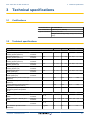
3.1
Certifications
CE identification no CE-0085CM0178
NOx classification 5 (EN 297 pr A3, EN 483)
Type of connection Chimney: B23, B33
Flue gas outlet: C13(x), C33(x), C43(x), C53, C83(x),
C93(x)
3.2
Technical specifications
Boiler type
AGC 10/15 AGC 15
AGC 25
AGC 35
General
Nominal output (Pn)
Heating System (80/60 °C)
minimummaximum
kW
3,0 - 10,1
3,0 - 14,5
5,0 - 24,1
6,3 - 34,0
Nominal output (Pn)
Heating System (50/30 °C)
minimummaximum
kW
3,4 - 11,2
3,4 - 15,8
5,6 - 25,5
7,0 - 35,9
Nominal output (Pn)
Heating System (40/30 °C)
minimummaximum
kW
3,4 - 16,0
3,4 - 16,0
5,6 - 25,9
7,0 - 36.4
Nominal input (Qn)
Heating System (Hi)
minimummaximum
kW
3,1 - 10,5
3,1 - 15,0
5,2 - 25,0
6,5 - 35,1
Nominal input(Qn)
Heating System (Hs)
minimummaximum
kW
3,4 - 11,7
3,4 - 16,7
5,8 - 27,8
7,2 - 39,0
Nominal input (Qnw)
DHW System (Hi)
minimummaximum
kW
3,1 - 15,0
3,1 - 15,0
5,2 - 29,3
6,5 - 35,1
Nominal input (Qnw)
DHW System (Hs)
minimummaximum
kW
3,4 - 16,7
3,4 - 16,7
5,8 - 32,6
7,2 - 39,0
Heating efficiency under full load (Hi) (80/60 °C)
%
96,5
96,5
96,3
96,9
Heating efficiency under full load (Hi) (50/30 °C)
%
105,3
105,3
102,0
102,2
Heating efficiency under partial load
(Hi) (Return temperature 60°C)
%
94,9
94,9
96,1
96,3
Heating efficiency under partial load (EN 92/42) (Return temperature
30°C)
Data on the gases and combustion gases
%
108,8
108,5
108,0
108,2
Gas consumption - Natural gas H
(G20)
minimummaximum
m3/h
0,33 - 1,59 0,33 - 1,59 0,55 - 3,10 0,69 - 3,71
Gas consumption - Natural gas L
(G25)
minimummaximum
m3/h
0,38 - 1,85 0,38 - 1,85 0,64 - 3,61 0,80 - 4,32
Gas consumption - Propane G31
minimummaximum
m3/h
0,13 - 0,61 0,13 - 0,61 0,21 - 1,20 0,27 - 1,44
mg/kWh
33
NOx-Emission (Scrolls forward
EN297A3)
18/12/2014 - 300026080-001-04
-
33
38
41
10
3. Technical specifications
AGC 10/15 AGC 15 AGC 25 AGC 35
AGC 10/15 AGC 15
AGC 25
AGC 35
Mass flue gas flow rate
Boiler type
minimummaximum
kg/h
5,3 - 25,2
5,3 - 25,2
8,9 - 49,3
11,1 - 57,3
Flue gas temperature
minimummaximum
°C
30 - 65
30 - 65
30 - 80
30 - 75
Maximum counter pressure
Characteristics of the heating circuit
Pa
22
80
120
140
Water content (ex expansion vessel)
l
1,9
1,9
1,9
2,5
Water operating pressure
minimum
kPa (bar (MPa)) 80 (0,8)
80 (0,8)
80 (0,8)
80 (0,8)
Water operating pressure (PMS)
maximum
kPa (bar (MPa)) 300 (3,0)
300 (3,0)
300 (3,0)
300 (3,0)
Water temperature
maximum
°C
110
110
110
110
Operating temperature
Electrical characteristics
maximum
°C
90
90
90
90
VAC
230
230
230
230
Power supply voltage
Power consumption - Full load
maximum
W
101
101
116
173
Power consumption - Part load
maximum
W
25
25
25
68
Power consumption - Standby
maximum
W
4
4
4
4
IP21
IP21
IP21
IP21
56
56
56
50
Electrical protection index
Other characteristics
Weight (empty)
11
kg
18/12/2014 - 300026080-001-04
AGC 10/15 AGC 15 AGC 25 AGC 35
4
Description
4.1
Operating principle
4. Description
4.1.1.
Gas/air setting
Air is sucked in by the fan and the gas injected into the venturi
attached to the fan inlet. The fan rotation speed modulates and adapts
to thermal energy requirements thanks to the temperatures measured
by the various sensors. The gas and air are mixed in the venturi, which
enables operation at a constant ratio. The noise of the venturi is
absorbed by a silencer attached to its inlet. The gas/air mixture is
carried to the burner in the top of the exchanger, guided by the premix channel.
4.1.2.
Combustion
The burner heats the heating water circulating in the heat
exchanger. At a return temperature lower than around 55°C, the flue
gases cool down to a temperature lower than the dew point, thus
causing the condensation of the water vapour contained in the flue
gases in the lower section of the heat exchanger. The heat released
during this condensation process (the latent heat or condensing heat)
is also transferred to the heating water. The cooled combustion gases
are evacuated via the combustion gas outlet flue. The condensation
water is evacuated via a condensate trap.
18/12/2014 - 300026080-001-04
12
4. Description
4.2
AGC 10/15 AGC 15 AGC 25 AGC 35
Main parts
4
3
2
5
6
1
Flue gas discharge pipe
2
Flue gas measuring point
19
3
Heat exchanger
18
4
Ignition/ionization electrode
17
5
Box for the control PCBs
16
6
Control panel
15
7
Command module
14
8
Water pressure sensor
13
9
Circulation pump
12
10
Hydroblock
11
11
3-way valve
10
12
Safety valve
9
13
Casing
C003072-C
14
Expansion vessel
15
Combined venturi and gas valve unit
16
Fan
17
Air intake silencer
18
Mixer pipe
19
Automatic air vent
1
7
8
13
18/12/2014 - 300026080-001-04
AGC 10/15 AGC 15 AGC 25 AGC 35
4.3
4. Description
Control panel
Description of the keys
A000866-A
4.3.1.
0
2
4
6
8
10
12
14
16
18
20
22
24
A
B
bar
p b AUTO x c g m
(
C
'
STD
j
M
t
F
E
D
A
Temperature setting key (heating, DHW, swimming pool)
B
Operating mode selection key
C
DHW override key
D
Key to access the parameters reserved for the installer
E
Keys on which the function varies as and when selections
are made
F
Rotary setting button:
4
4
18/12/2014 - 300026080-001-04
r
Turn the rotary button to scroll through the menus or
modify a value
Press the rotary button to access the selected menu
or confirm a value modification
14
4. Description
AGC 10/15 AGC 15 AGC 25 AGC 35
4.3.2.
Description of the display
n Key functions
bar
2
4
6
8
10
12
14
r
p b AUTO x c g m
(
'
r
16
18
j
20
22
L
t
STD
>
Access to the various menus
(
Used to scroll through the menus
’
Used to scroll through the parameters
?
The symbol is displayed when help is available
f
Used to display the curve of the parameter selected
STD
Reset of the time programmes
b
Selection of comfort mode or selection of the days to be
programmed
v
Selection of reduced mode or deselection of the days to
be programmed
j
Back to the previous level
ESC
Back to the previous level without saving the
modifications made
t
Manual reset
24
C002696-A
0
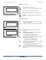
n Flame output level
2
4
6
8
10
12
14
16
18
20
22
24
C002705-A
0
The whole symbol flashes: The burner starts up but the
flame is not yet present
Part of the symbol flashes: Output is increasing
M
t
Steady symbol: The required output has been reached
C002703-A
STD
r
C002701-B
p b AUTO x c g m
j
C002704-A
bar
C002702-A
Part of the symbol flashes: Output is dropping
15
18/12/2014 - 300026080-001-04
AGC 10/15 AGC 15 AGC 25 AGC 35
4. Description
n Solar (If connected)
The solar load pump is running
u
2
4
6
8
10
12
14
16
18
20
22
24
L000201-A
L000200-A
0
bar
M
t
L000199-A
STD
L000198-A
r
L000197-A
p b AUTO x c g m
j
The top part of the tank is reheated to the tank set point
The entire tank is reheated to the tank set point
The entire tank is reheated to the solar tank set point
The tank is not loaded - Presence of the solar control
system
n Operating modes
0
2
4
6
8
10
12
14
16
18
20
22
p
Summer mode: The heating is off. Domestic hot water
continues to be produced
b
WINTER mode: Heating and domestic hot water working
AUTO
Operation in automatic mode according to the timer
programme
x
Comfort mode: The symbol is displayed when a DAY
override (comfort) is activated
24
bar
r
j
t
STD
0
2
4
6
8
10
M
C002697-B
p b AUTO x c g m
12
14
16
18
20
22
24
bar
r
STD
j
M
t
C002698-B
p b AUTO x c g m
m
g
m
18/12/2014 - 300026080-001-04
4
Flashing symbol: Temporary override
4
Steady symbol: Permanent override
Reduced mode: The symbol is displayed when a NIGHT
override (reduced) is activated
4
Flashing symbol: Temporary override
4
Steady symbol: Permanent override
Holiday mode: The symbol is displayed when a HOLIDAY
override (antifreeze) is activated
4
Flashing symbol: Holiday mode programmed
4
Steady symbol: Holiday mode active
Manual mode: The boiler operates with the displayed set
point. All of the pumps operate. The 3-way valves are not
controlled.
16
4. Description
AGC 10/15 AGC 15 AGC 25 AGC 35
n System pressure
bar
0
2
4
6
8
10
12
14
16
18
20
22
24
bar
r
j
l
M
C002708-A
p b AUTO x c g m
t
STD
Pressure indicator: The symbol is displayed when a water
pressure sensor is connected.
4
Flashing symbol: The water pressure is insufficient.
4
Steady symbol: The water pressure is sufficient.
Water pressure level
4
R: 0,9 to 1,1 bar
4
E: 1,2 to 1,5 bar
4
Z: 1,6 to 1,9 bar
4
A: 2,0 to 2,3 bar
4
l: > 2,4 bar
n Domestic Hot Water override
A bar is displayed when a DHW override is activated:
0
2
4
6
8
10
12
14
16
18
20
22
24
4
Flashing bar: Temporary override
4
Steady bar: Permanent override
bar
r
j
M
C002707-A
p b AUTO x c g m
t
STD
n Other information
0
2
4
6
8
10
12
14
16
18
20
22
r
The symbol is displayed when domestic hot water
production is running.
w
Valve indicator: The symbol is displayed when a 3-way
valve is connected.
24
bar
STD
r
j
M
t
C002699-B
p b AUTO x c g m
M
4
x: 3-way valve opens
4
c: 3-way valve closes
The symbol is displayed when the pump is operating.
Name of the circuit for which the parameters are
displayed.
17
18/12/2014 - 300026080-001-04
AGC 10/15 AGC 15 AGC 25 AGC 35
4. Description
4.3.3.
0
4
6
8
10
12
14
16
#MEASURES
#CHOICE TIME PROG.
#TIME PROGRAM
#SETTING
c #TIME .DAY
r
v
bar
2
18
20
22
24
a
1
2
1
2
p b AUTO x c g m
(
'
r
j
Browsing in the menus
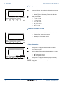
1. To select the desired menu, turn the rotary button.
2. To access the menu, press the rotary button.
To go back to the previous display, press the key j.
L
t
STD
C002220-B-04
0
2
4
6
8
10
12
14
16
18
20
CURRENT PROG.B
CURRENT PROG.C
v
bar
c
22
24
a
P2
P3
1
2
1
2
r
p b AUTO x c g m
(
'
r
j
3. To select the desired parameter, turn the rotary button.
4. To modify the parameter, press the rotary button.
To go back to the previous display, press the key j.
L
t
STD
C002221-C-04
0
v
bar
c
1
2
4
6
8
10
12
14
16
18
20
CURRENT PROG.C
"Choice of the timeprogram
applied C"
22
24
a
P4
2
1
2
r
p b AUTO x c g m
(
'
r
j
5. To modify the parameter, turn the rotary button.
6. To confirm, press the rotary button.
To cancel, press key h.
L
t
STD
C002222-C-04
7. To go back to the main display, press key j2 times.
0
2
4
6
8
10
12
14
16
18
20
22
24
2x
LUNDI 11:45
v
bar
c
1
It is possible to use the ( and ’ keys instead of the rotary
button.
2
1
2
r
p b AUTO x c g m
(
'
r
STD
j
M
t
C002224-D-04
18/12/2014 - 300026080-001-04
18
5. Operating the appliance
AGC 10/15 AGC 15 AGC 25 AGC 35
5
Operating the appliance
5.1
Putting the appliance into operation
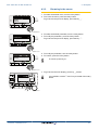
1. Turn on the boiler using the on/off switch.
8
20
22
24
0
l
C003159-A
0
v
bar
c
1
2
1
2
2
4
6
8
10
12
14
16
18
20
22
2. The first time the boiler is powered up, the LANGUAGE menu is
displayed. Select the desired language by turning the rotary
button.
3. To confirm, press the rotary button.
The boiler will begin an automatic venting-programme (which lasts
approx. 3 minutes) and will do this every time the power supply is
isolated. If there is a problem, the error is displayed on the screen.
4. Check the water pressure in the installation shown on the control
panel display.
24
ÿ
LANGUE
FRANCAIS
Français - Deutsch - English Italiano - Espanol - Nederlands
- Pycck - Polski - Türk -
r
pb
xc
(
'
gm r
t
STD
C002286-C
5.2
If the water pressure is lower than 0,8 bar, more water
should be added. If necessary, top up the water level in the
heating system (recommended hydraulic pressure
between 1,5 and 2,0 bar).
Reading out measured values
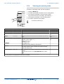
The various values measured by the appliance are displayed in the
#MEASURES menu.
1. To access user level: Press the > key.
0
2
4
6
8
10
12
14
16
18
20
22
24
SUNDAY 11:45
v
bar
c
Turn the rotary button to scroll through the menus or
modify a value.
4 Press the rotary button to access the selected menu
or confirm a value modification.
¼For a detailed explanation of menu browsing, refer to
the chapter: "Browsing in the menus", page 18.
4
1
2
1
2
r
p b AUTO x c g m
(
2. Select the menu #MEASURES.
'
STD
r
j
M
t
C002219-D-04
19
18/12/2014 - 300026080-001-04
AGC 10/15 AGC 15 AGC 25 AGC 35
5. Operating the appliance
User level - #MEASURES Menu
Parameter
Description
Unit
OUTSIDE TEMP.
Outside temperature
°C
ROOMTEMP.A (1)
Room temperature of circuit A
°C
ROOMTEMP.B (1)
Room temperature of circuit B
°C
(1)
Room temperature of circuit C
°C
BOILER TEMP
Water temperature in the boiler
°C
PRESSURE
Water pressure in the installation
bar (MPa)
Water temperature in the DHW tank
°C
Instant hot water temperature
°C
Water temperature in the storage tank
°C
ROOMTEMP.C
WATER TEMP.
(1)
TEMP DHW INST
(1)
STOR.TANK.TEMP
(1)
SWIMMING P.T.B (1) Water temperature of the swimming pool on circuit B
°C
SWIMMING P.T.C
(1)
Water temperature of the swimming pool on circuit C
°C
OUTLET TEMP.B
(1)
Temperature of the flow water in circuit B
°C
OUTLET TEMP.C
(1)
Temperature of the flow water in circuit C
°C
Temperature of the system flow water if multi-generator
°C
Water temperature in the bottom of the DHW tank
°C
TEMP.TANK AUX (1) Water temperature in the second DHW tank connected to the AUX circuit
°C
TEMP.SYSTEM
(1)
T.DHW BOTTOM (1)
DHW A TEMP. (1)
TEMP.SOL.TANK
SOLAR.COLL.T.
(1)
(1)
Water temperature in the second DHW tank connected to circuit A
°C
Temperature of the hot water produced by solar power (TS)
°C
Solar panel temperature (TC)
°C
Solar energy accumulated in the tank
kWh
BACK TEMP
Temperature of the boiler return water
°C
FAN SPEED
Fan rotation speed
rpm
POWER
Instantaneous boiler output (0%: Burner off or running at minimum output)
%
Ionization current
µA
Energy consumed by the boiler in heating mode (estimated value)
kWh
DHW CONS. (2)
Energy consumed by the boiler in DHW mode (estimated value)
kWh
NB IMPULS.
Number of burner starts (not restartable)
The meter is incremented by 8 every 8 start-ups
RUNTIME
Number of burner operation hours (not restartable)
The meter is incremented by 2 every 2 hours
h
IN 0-10V (1)
Voltage at input 0-10 V
V
SEQUENCE
Control system sequence
CTRL
Software control number
SOLA.ENERGY
CURRENT (µA)
HEATCONS.
(2)
(1)
(1) The parameter is only displayed for the options, circuits or sensors actually connected.
(2) The parameter is only displayed if the function is activated (parameter ENERGY METER in the #CONFIGURATION menu)
18/12/2014 - 300026080-001-04
20
5. Operating the appliance
5.3
AGC 10/15 AGC 15 AGC 25 AGC 35
Changing the settings
5.3.1.
Setting the set point temperatures
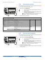
To set the various heating, DHW and swimming pool temperatures,
proceed as follows:
1. Press the C key.
2. To select the desired parameter, turn the rotary button.
3. To modify the parameter, press the rotary button.
To go back to the previous display, press the key j.
4. To modify the parameter, turn the rotary button.
5. To confirm, press the rotary button.
MODE
To cancel, press key h.
C002266-A
C Menu
Parameter
Adjustment range Description
Factory setting
DAY TEMP.A
5 to 30 °C
Desired room temperature in comfort periods on circuit A
20 °C
NIGHT TEMP.A
5 to 30 °C
Desired room temperature in reduced periods on circuit A
16 °C
5 to 30 °C
Desired room temperature in comfort periods on circuit B
20 °C
5 to 30 °C
Desired room temperature in reduced periods on circuit B
16 °C
5 to 30 °C
Desired room temperature in comfort periods on circuit C
20 °C
5 to 30 °C
Desired room temperature in reduced periods on circuit C
16 °C
10 to 80 °C
Desired domestic hot water temperature in the DHW circuit
55 °C
10 to 90 °C
Desired domestic hot water temperature in the auxiliary circuit 55 °C
10 to 90 °C
Desired domestic hot water temperature in circuit A
55 °C
20 to 80 °C
Maximum load temperature of the tank’s solar zone
65 °C
SWIMMING P.T.B (1)
HG / 0.5 to 39 °C
Desired temperature for swimming pool B
20 °C
(1)
HG / 0.5 to 39 °C
Desired temperature for swimming pool C
20 °C
Desired domestic hot water temperature in the DHW circuit
10 °C
DAY TEMP.B
(1)
NIGHT TEMP.B
DAY TEMP.C
(1)
(1)
NIGHT TEMP.C (1)
DHW TEMP.
(1)
TEMP.TANK AUX
DHW A TEMP.
(1)
(1)
TEMP.SOL.TANK
(1)
(2)
SWIMMING P.T.C
10 to 80 °C
WATER T.NIGHTAUX 10 to 90 °C
WATER T.NIGHT.A
10 to 90 °C
WATER T.NIGHT
Desired domestic hot water temperature in the auxiliary circuit 10 °C
Desired domestic hot water temperature in circuit A
10 °C
(1) The parameter is only displayed for the options, circuits or sensors actually connected.
(2) The menu is only displayed if the solar control system is connected
21
18/12/2014 - 300026080-001-04
AGC 10/15 AGC 15 AGC 25 AGC 35
5. Operating the appliance
5.3.2.
Selecting the operating mode
To select an operating mode, proceed as follows:
1. Press the MODE key.
2. To select the desired parameter, turn the rotary button.
3. To modify the parameter, press the rotary button.
To go back to the previous display, press the key j.
4. To modify the parameter, turn the rotary button.
5. To confirm, press the rotary button.
MODE
To cancel, press key h.
C002267-A
MODE Menu
Parameter
Adjustment range Description
Factory setting
The comfort ranges are determined by the timer programme.
AUTOMATIQUE
DAY
7/7, xx:xx
Comfort mode is forced until the time indicated or all the time (7/7). Present time + 1
hour
NIGHT
7/7, xx:xx
Reduced mode is forced until the time indicated or all the time
(7/7).
Present time + 1
hour
HOLIDAYS
7/7, 1 to 364
The antifreeze mode is active on all boiler circuits.
Number of days’ holiday: xx (1)
heating OFF: xx:xx (1)
Restarting: xx:xx (1)
Present date + 1
day
SUMMER
The heating is off.
Domestic hot water continues to be produced.
MANUEL
The generator operates according to the set point setting. All of
the pumps operate. Option of setting the set point by simply
turning the rotary button.
FORCE AUTO (2) YES / NO
An operating mode override is activated on the remote control
(option).
To force all circuits to run on AUTOMATIQUE mode, select
YES.
(1) The start and end days and the number of days are calculated in relation to each other.
(2) The parameter is only displayed if a room sensor is connected.
18/12/2014 - 300026080-001-04
22
5. Operating the appliance
AGC 10/15 AGC 15 AGC 25 AGC 35
5.3.3.
Forcing domestic hot water production
To force domestic hot water production, proceed as follows:
1. Press the r key.
2. To select the desired parameter, turn the rotary button.
3. To modify the parameter, press the rotary button.
To go back to the previous display, press the key j.
4. To modify the parameter, turn the rotary button.
5. To confirm, press the rotary button.
MODE
To cancel, press key h.
C002268-A
r Menu
Parameter
Description
Factory setting
AUTOMATIQUE The domestic hot water comfort ranges are determined by the timer programme.
COMFORT
Domestic hot water comfort mode is forced until the time indicated or all the time (7/7). Present time + 1 hour
5.3.4.
Setting the contrast and lighting on the
display
1. To access user level: Press the > key.
0
2
4
6
8
10
12
14
16
18
20
22
2. Select the menu #SETTING.
24
SUNDAY 11:45
v
bar
c
Turn the rotary button to scroll through the menus or
modify a value.
4 Press the rotary button to access the selected menu
or confirm a value modification.
¼For a detailed explanation of menu browsing, refer to
the chapter: "Browsing in the menus", page 18.
4
1
2
1
2
r
p b AUTO x c g m
(
'
r
STD
j
M
t
C002219-D-04
3. Set the following parameters:
User level - #SETTING Menu
Parameter
Adjustment range Description
BACK LIGHT
23
Factory setting Customer setting
Adjusting the display contrast.
CONTRAST DISP.
COMFORT
The screen is illuminated continuously in
daytime periods.
ECO
The screen is illuminated for 2 minutes
whenever pressed.
ECO
18/12/2014 - 300026080-001-04
5. Operating the appliance
AGC 10/15 AGC 15 AGC 25 AGC 35
5.3.5.
Setting the time and date
1. To access user level: Press the > key.
0
2
4
6
8
10
12
14
16
18
20
22
24
2. Select the menu #TIME .DAY.
SUNDAY 11:45
v
bar
c
Turn the rotary button to scroll through the menus or
modify a value.
4 Press the rotary button to access the selected menu
or confirm a value modification.
¼For a detailed explanation of menu browsing, refer to
the chapter: "Browsing in the menus", page 18.
4
1
2
1
2
r
p b AUTO x c g m
(
'
r
j
M
t
STD
C002219-D-04
3. Set the following parameters:
User level - #TIME .DAY Menu (1)
Parameter Adjustment range
Description
HOURS
0 to 23
Hours setting
MINUTE
0 to 59
Minutes setting
DAY
Monday to Sunday
Setting the day of the week
DATE
1 to 31
Day setting
MONTH
January to December Month setting
2008 to 2099
SUM.TIME AUTO
Factory setting Customer setting
Year setting
YEAR
automatic switch to summer time on the last Sunday AUTO
in March and back to winter time on the last Sunday
in October.
for countries where the time change is done on other
dates or is not in use.
MANU
(1) According to the configuration
5.3.6.
Selecting a timer programme
1. To access user level: Press the > key.
0
2
4
6
8
10
12
14
16
18
20
22
24
SUNDAY 11:45
v
bar
c
Turn the rotary button to scroll through the menus or
modify a value.
4 Press the rotary button to access the selected menu
or confirm a value modification.
¼For a detailed explanation of menu browsing, refer to
the chapter: "Browsing in the menus", page 18.
4
1
2
1
2
r
p b AUTO x c g m
(
2. Select the menu #CHOICE TIME PROG..
'
r
STD
j
M
t
C002219-D-04
18/12/2014 - 300026080-001-04
3. To select the desired parameter.
4. Assign the desired timer programme (P1 to P4) to the circuit with
the rotary button.
24
AGC 10/15 AGC 15 AGC 25 AGC 35
5. Operating the appliance
User level - #CHOICE TIME PROG. Menu
Parameter
Adjustment range Description
CURRENT PROG.A P1 / P2 / P3 / P4
Comfort programme activated
(Circuit A)
CURRENT PROG.B P1 / P2 / P3 / P4
Comfort programme activated
(Circuit B)
CURRENT PROG.C P1 / P2 / P3 / P4
Comfort programme activated
(Circuit C)
5.3.7.
Customising a timer programme
1. To access user level: Press the > key.
0
2
4
6
8
10
12
14
16
18
20
22
2. Select the menu #TIME PROGRAM.
24
SUNDAY 11:45
v
c
bar
Turn the rotary button to scroll through the menus or
modify a value.
4 Press the rotary button to access the selected menu
or confirm a value modification.
¼For a detailed explanation of menu browsing, refer to
the chapter: "Browsing in the menus", page 18.
4
1
2
1
2
r
p b AUTO x c g m
(
'
r
j
M
t
STD
C002219-D-04
3. To select the desired parameter.
User level - #TIME PROGRAM Menu
0
v
bar
c
1
2
1
2
2
4
6
8
10
12
14
16
18
20
22
PROG P2 C
Mo Tu We Th Fr Sa Su
"Display of the timeprogram.
To continuepush on the button"
r
p b AUTO x c g m
(
'
STD
r
j
24
a
Parameter
Time schedule Description
TIME PROG.A
PROG P2 A
PROG P3 A
PROG P4 A
Timer programme for circuit A
TIME PROG.B
PROG P2 B
PROG P3 B
PROG P4 B
Timer programme for circuit B
TIME PROG.C
PROG P2 C
PROG P3 C
PROG P4 C
Timer programme for circuit C
TIME PROG.DHW
DHW circuit timer programme
TIME PROG.AUX
Auxiliary circuit timer programme
4. To select a timer programme to be modified.
5. To select to days for which the timer programme is to be
modified:
Turn the rotary button to the left until you reach the day desired.
To confirm, press the rotary button.
L
t
C002228-B-04
25
18/12/2014 - 300026080-001-04
AGC 10/15 AGC 15 AGC 25 AGC 35
0
v
bar
c
1
2
1
2
2
4
6
8
10
12
14
16
18
PROG P2 C
Mo Tu We Th Fr
"Select the days to
program"
r
p b AUTO x c g m
(
'
r
20
Sa
j
22
5. Operating the appliance
24
a
Su
L
t
STD
6. b: Day selection
Press key b / v until the symbol b is displayed.
Turn the rotary button to the right to select the day(s) desired.
v: Cancelling the day selection
Press key b / v until the symbol v is displayed.
Turn the rotary button to the right to cancel selection of the relevant
day(s).
7. When the days desired for the programme have been selected,
press the rotary button to confirm.
C002229-C-04
06:00
0
v
bar
c
1
2
4
6
8
10
12
14
16
18
PROG P2 C
Mo Tu We Th Fr
Set the time program.
20
22
24
a
06:00
Sa Su
2
1
2
r
p b AUTO x c g m
(
'
r
STD
j
L
t
8. To define the timer ranges for the comfort mode and reduced
mode:
Turn the rotary button to the left until 0:00 is displayed. The first
segment of the graphic bar for the timer programme flashes.
9. b: Comfort mode selection
Press key b / v until the symbol b is displayed.
To select a comfort time range, turn the rotary button to the right.
v: Reduced mode selection
Press key b / v until the symbol v is displayed.
To select a reduced time range, turn the rotary button to the right.
10.When the times for the comfort mode have been selected, press
the rotary button to confirm.
C002230-E-04
User level - #TIME PROGRAM Menu
Day
Comfort periods / Filling enabled:
P1
P2 _______________ P3 _______________ P4 _______________
_______________
TIME PROG.A
Monday
6:00 to 22:00
Tuesday
6:00 to 22:00
Wednesday 6:00 to 22:00
TIME PROG.B
Thursday
6:00 to 22:00
Friday
6:00 to 22:00
Saturday
6:00 to 22:00
Sunday
6:00 to 22:00
Monday
6:00 to 22:00
Tuesday
6:00 to 22:00
Wednesday 6:00 to 22:00
TIME PROG.C
Thursday
6:00 to 22:00
Friday
6:00 to 22:00
Saturday
6:00 to 22:00
Sunday
6:00 to 22:00
Monday
6:00 to 22:00
Tuesday
6:00 to 22:00
Wednesday 6:00 to 22:00
Thursday
6:00 to 22:00
Friday
6:00 to 22:00
Saturday
6:00 to 22:00
Sunday
6:00 to 22:00
18/12/2014 - 300026080-001-04
26
AGC 10/15 AGC 15 AGC 25 AGC 35
5. Operating the appliance
User level - #TIME PROGRAM Menu
Day
Comfort periods / Filling enabled:
P1
P2 _______________ P3 _______________ P4 _______________
_______________
TIME PROG.DHW Monday
Tuesday
Wednesday
Thursday
Friday
Saturday
Sunday
TIME PROG.AUX
Monday
Tuesday
Wednesday
Thursday
Friday
Saturday
Sunday
5.4
Installation shutdown
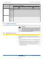
CAUTION
Do not switch off the mains supply to the appliance. If the
central heating system is not used for a long period, we
recommend activating the HOLIDAYS mode (to ensure
the anti-grip of the heating pump).
5.5
Antifreeze protection
When the heating water temperature in the boiler is too low, the
integrated boiler protection system starts up. This protection functions
as follows:
4 If the water temperature is lower than 7°C, the heating pump starts
up.
4 If the water temperature is lower than 4°C, the boiler starts up.
4 If the water temperature is higher than 10°C, the boiler shuts down
and the circulation pump continues to run for a short time.
4 If the water temperature in the storage tank is less than 4°C, it is
reheated to its set point.
27
18/12/2014 - 300026080-001-04
AGC 10/15 AGC 15 AGC 25 AGC 35
5. Operating the appliance
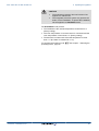
CAUTION
4
4
The antifreeze protection does not function if the
appliance is switched off.
The integrated protection system only protects the
boiler, not the installation. To protect the installation,
set the appliance to HOLIDAYS mode.
The HOLIDAYS mode protects:
4 The installation if the outside temperature is lower than 3°C
(factory setting).
4 The room temperature if a remote control is connected and the
room temperature is lower than 6 °C (factory setting).
4 The domestic hot water tank if the tank temperature is lower
than 4 °C (the water is reheated to 10 °C).
To configure the holidays mode: ¼See chapter: "Selecting the
operating mode", page 22.
18/12/2014 - 300026080-001-04
28
6. Checking and maintenance
AGC 10/15 AGC 15 AGC 25 AGC 35
6
Checking and maintenance
6.1
General instructions
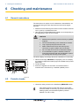
The boiler does not require a lot of maintenance. Nevertheless, we
recommend having the boiler inspected and serviced at regular
intervals.
4 Maintenance and cleaning of the boiler must be carried out at least
once a year by a qualified technician.
4 Have the flues swept at least once a year or more, depending on
the regulations in force in your country.
CAUTION
4
Maintenance operations must be done by a qualified
engineer.
We recommend taking out a maintenance contract.
4
Only original spare parts must be used.
4
Make certain that the flues and chimneys are
connected, in good condition and not blocked.
Do not modify nor block the condensate outlet(s).
4
4
4
If a neutralisation system is installed, follow the
instructions delivered with the neutralisation system
for cleaning and servicing of this system.
The boiler displays a message whenever maintenance is necessary.
0
2
4
6
8
10
12
14
16
18
20
22
24
SUNDAY 11:45
v
bar
c
1
TEMP. : 68°
2
1
2
r PCU COM.FAIL D27
p b AUTO x c g m
(
'
STD
r
j
M
t
1. When the message, REVISION, is displayed, press ? to display
the installer’s telephone number (only if the installer has input this
parameter).
2. Contact the fitter.
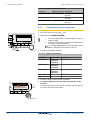
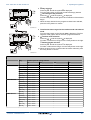
3. Ensure the Appliance is serviced in accordance with the
manufacturer’s instructions by a suitable qualified person.
C002302-D-04
6.2
Periodic checks
4 Check the water pressure in the installation (MEASURE mode).
If the water pressure is lower than 0,8 bar, more water
should be added. If necessary, top up the water level in the
heating system (recommended hydraulic pressure
between 1,5 and 2,0 bar).
29
18/12/2014 - 300026080-001-04
AGC 10/15 AGC 15 AGC 25 AGC 35
6. Checking and maintenance
4 Carry out a visual check for the presence of any water leaks.
T001507-B
4 Open and close the radiator valves several times a year (this
prevents the valves from seizing up).
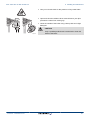
4 Clean the outside of the boiler using a damp cloth and a light
detergent.
1
2
CAUTION
3
4
T000181-B
18/12/2014 - 300026080-001-04
Only a qualified professional is authorised to clean the
inside of the boiler.
30
7. Troubleshooting
AGC 10/15 AGC 15 AGC 25 AGC 35
7
Troubleshooting
7.1
Anti-hunting
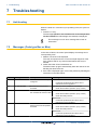
When the boiler is in Anti-short-cycle operating mode, the symbol ?
flashes.
1. Press the "?" key.
The message Operation assured when the restart temperature
will be reachede de redémarrage sera atteinte} is displayed.
This message is not an error message but an item of
information.
7.2
Messages (Code type Bxx or Mxx)
In the case of failure, the control panel displays a message and a
corresponding code.
1. Make a note of the code displayed.
The code is important for the correct and rapid diagnosis of the
type of failure and for any technical assistance that may be
needed.
2. Switch the boiler off and switch back on.
The boiler starts up again automatically when the reason for the
blocking has been removed.
3. If the code is displayed again, correct the problem by following the
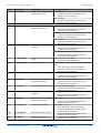
instructions in the table below:
Code
Messages
Description
Checking / solution
B00
BL.PSU ERROR
The PSU PCB is incorrectly
configured
Parameter error on the PSU PCB
Maximum flow temperature
exceeded
Contact the professional who takes care of
maintenance of the appliance
The water flow in the installation is insufficient
4
B01
BL.BOILER MAX
B02
4
Check the circulation (direction, pump, valves)
BL.HEATING SPEED The increase in flow temperature The water flow in the installation is insufficient
has exceeded its maximum limit
4
Check the circulation (direction, pump, valves)
4
Check the water pressure
Sensor error
Contact the professional who takes care of
maintenance of the appliance
The water flow in the installation is insufficient
4
B07
BL.DT OUTL RET.
Maximum difference between
the flow and return temperature
4
Check the circulation (direction, pump, valves)
exceeded
4
Check the water pressure
Sensor error
4
31
Contact the professional who takes care of
maintenance of the appliance
18/12/2014 - 300026080-001-04
AGC 10/15 AGC 15 AGC 25 AGC 35
7. Troubleshooting
Code
Messages
Description
Checking / solution
B08
BL.RL OPEN
The RL inlet on the PCU PCB
terminal block is open
Parameter error
Contact the professional who takes care of
maintenance of the appliance
Bad connection
4
Contact the professional who takes care of
maintenance of the appliance
4
Contact the professional who takes care of maintenance of the appliance
The BL inlet on the PCU PCB
The contact connected to the BL inlet is open
terminal block is open
4
Contact the professional who takes care of
maintenance of the appliance
Parameter error
4
B09
BL.INV.L/N
B10
B11
BL.SC.IN.OPEN
Contact the professional who takes care of
maintenance of the appliance
Bad connection
4
Contact the professional who takes care of
maintenance of the appliance
Bad connection
4
B13
BL. PCU COM
Communication error with the
SCU PCB
Contact the professional who takes care of
maintenance of the appliance
SCU PCB not installed in the boiler
4
Contact the professional who takes care of
maintenance of the appliance
The water pressure is lower than Not enough water in the circuit
0,8 bar
4
Top up the installation with water
Gas pressure too low
Incorrect setting of the gas pressure switch on the SCU
PCB
4
B14
BL.WATER MIS.
B15
BL.GAS PRESS
4
Check that the gas valve is fully opened
Contact the professional who takes care of
maintenance of the appliance
Wrong SU PCB for this boiler
4
B16
BL.BAD SU
The SU PCB is not recognised
Contact the professional who takes care of
maintenance of the appliance
Parameter error on the PCU PCB
4
B17
B18
BL.BAD PSU
BL.BAD PSU
The parameters saved on the
PCU PCB are impaired
Contact the professional who takes care of
maintenance of the appliance
The PSU PCB is not recognised Wrong PSU PCB for this boiler
4
Contact the professional who takes care of
maintenance of the appliance
The PSU PCB has been changed
4
B19
B21
B22
BL.NO CONFIG
BL.COM SU
BL.FLAME LOS
The boiler has not been
configured
Communication error between
the PCU and SU PCBs
No flame during operation
Contact the professional who takes care of
maintenance of the appliance
Bad connection
4
Contact the professional who takes care of
maintenance of the appliance
No ionization current
4
4
Check that the gas valve is fully opened
4
Contact the professional who takes care of
maintenance of the appliance
Contact the professional who takes care of
maintenance of the appliance
Contact the professional who takes care of
maintenance of the appliance
B25
BL.SU ERROR
Internal error on the SU PCB
4
B26
BL.DHW. S.
The DHW tank sensor is
disconnected or short circuited
4
18/12/2014 - 300026080-001-04
32
AGC 10/15 AGC 15 AGC 25 AGC 35
7. Troubleshooting
Code
Messages
Description
B27
BL.DHW INST
The sensor on the plate
4
exchanger outlet is disconnected
or short circuited
Checking / solution
Contact the professional who takes care of
maintenance of the appliance
B28
BL.BAD.CONFIG
An HL tank is detected whilst the 4
boiler cannot control it.
4
This message disappears after
10 seconds if the boiler can
control the HL tank
Wait for 10 seconds to see whether the error persists
Contact the professional who takes care of
maintenance of the appliance
Contact the professional who takes care of
maintenance of the appliance
B29 to
B34
BL.UNKNOWN Bxx
Incorrect configuration of the
PCU
M04
REVISION
A service is required
M05
REVISION A
If the symbol ? flashes, press key ?. The installer’s
contact details are displayed.
4
Contact the professional who takes care of
maintenance of the appliance
An A, B or C service is required The date programmed for the service has been reached
M06
REVISION B
M07
REVISION C
M20
DISGAS
4
The date programmed for the service has been reached
4
If the symbol ? flashes, press key ?. The installer’s
contact details are displayed.
4
Contact the professional who takes care of
maintenance of the appliance
Switching the boiler on
4
A boiler vent cycle is underway
Floor drying is active
XX DAYS = Number of days’
floor drying remaining.
FL.DRY.B XX DAYS
FL.DRY.C XX DAYS
4
Wait 3 minutes
Floor drying is underway. Heating on the circuits not
concerned is shut down.
Contact the professional who takes care of
maintenance of the appliance
The outside temperature sensor Change the outside radio temperature sensor.
is defective.
FL.DRY.B+C XX
DAYS
4
M23
CHANGE OUTSI.S
M30
BL.SYSTEM
NETWORK
No communication with the
master regulation through the
MODBUS network
4
Contact the professional who takes care of
maintenance of the appliance
M31
BL.COM MODBUS
Incorrect configuration of the
MODBUS network
4
Contact the professional who takes care of
maintenance of the appliance
7.3
Faults (Code type Lxx or Dxx)
In the event of operational failure, the control panel flashes and
displays an error message and a corresponding code.
0
2
4
6
8
10
12
14
16
18
20
22
24
SUNDAY 11:45
v
bar
c
1
TEMP. : 68°
2
1
2
r PCU. COM. FAIL. D27
p b AUTO x c g m
(
STD
r
j
M
t
1. Make a note of the code displayed.
The code is important for the correct and rapid diagnosis of the
type of failure and for any technical assistance that may be
needed.
2. Press the t key. If the code is displayed again, switch off the boiler
and then switch it back on.
C002604-B-04
33
18/12/2014 - 300026080-001-04
AGC 10/15 AGC 15 AGC 25 AGC 35
0
2
4
6
8
10
12
14
16
18
20
22
7. Troubleshooting
3. Press the ? key. Follow the instructions displayed to solve the
problem.
4. Consult the meaning of the codes in the table below:
24
SUNDAY 11:45
v
bar
c
1
TEMP. : 68°
2
1
2
r PCU COM.FAIL D27
p b AUTO x c g m
(
'
r
STD
j
M
t
C002302-D-04
Code Faults
Cause
of the
fault
Description
Checking / solution
L00
PCU
PSU PCB not connected
Bad connection
PSU PCB faulty
PSU FAIL
Contact the professional who takes care of
maintenance of the appliance
The safety parameters are incorrect Bad connection
PSU PCB faulty
4
L01
PSU PARAM FAIL
PCU
Contact the professional who takes care of
maintenance of the appliance
Bad connection
Sensor fault
4
L02
DEF.OUTLET S.
PCU
The boiler flow sensor has shortcircuited
Contact the professional who takes care of
maintenance of the appliance
The boiler flow sensor is on an open Bad connection
circuit
Sensor fault
4
L03
DEF.OUTLET S.
PCU
Contact the professional who takes care of
maintenance of the appliance
Bad connection
Sensor fault
4
L04
DEF.OUTLET S.
PCU
Boiler temp too low
Contact the professional who takes care of
maintenance of the appliance
No water circulation
4
4
Vent the air in the heating system
Check the circulation (direction, pump,
valves)
4
Check the water pressure
Bad connection
Sensor fault
4
L05
STB OUTLET
PCU
Boiler temperature too high
Contact the professional who takes care of
maintenance of the appliance
No water circulation
4
4
Vent the air in the heating system
Check the circulation (direction, pump,
valves)
4
Check the water pressure
The return temperature sensor has Bad connection
short-circuited
Sensor fault
4
L06
BACK S.FAILURE
PCU
4
18/12/2014 - 300026080-001-04
Contact the professional who takes care of
maintenance of the appliance
34
7. Troubleshooting
AGC 10/15 AGC 15 AGC 25 AGC 35
Code Faults
Cause
of the
fault
Description
L07
PCU
The return temperature sensor is on Bad connection
an open circuit
Sensor fault
BACK S.FAILURE
Checking / solution
Contact the professional who takes care of
maintenance of the appliance
Bad connection
Sensor fault
4
L08
BACK S.FAILURE
PCU
Return temperature too low
Contact the professional who takes care of
maintenance of the appliance
No water circulation
4
4
Vent the air in the heating system
Check the circulation (direction, pump,
valves)
4
Check the water pressure
Bad connection
Sensor fault
4
L09
STB BACK
PCU
Return temperature too high
Contact the professional who takes care of
maintenance of the appliance
No water circulation
4
4
Vent the air in the heating system
Check the circulation (direction, pump,
valves)
4
Check the water pressure
Bad connection
Sensor fault
4
L10
DT RET-DEP>MAX
PCU
Difference between the flow and
return temperatures insufficient
Contact the professional who takes care of
maintenance of the appliance
No water circulation
4
4
Vent the air in the heating system
Check the circulation (direction, pump,
valves)
4
Check the water pressure
Bad connection
Sensor fault
4
L11
DEP-RET>MAX
PCU
Difference between the flow and
return temperatures too great
Contact the professional who takes care of
maintenance of the appliance
No water circulation
4
4
Vent the air in the heating system
Check the circulation (direction, pump,
valves)
4
Check the water pressure
Bad connection
Sensor fault
4
L12
STB OPEN
PCU
Maximum boiler temperature
exceeded (STB thermostat
maximum)
Contact the professional who takes care of
maintenance of the appliance
No water circulation
4
4
Vent the air in the heating system
4
Check the circulation (direction, pump,
valves)
Check the water pressure
4
35
18/12/2014 - 300026080-001-04
AGC 10/15 AGC 15 AGC 25 AGC 35
Code Faults
L14
Cause
of the
fault
BURNER FAILURE PCU
7. Troubleshooting
Description
Checking / solution
5 burner start-up failures
No ignition
Contact the professional who takes care of
maintenance of the appliance
Ignition arc, but no flame formation
4
4
Check that the gas valve is fully opened
Contact the professional who takes care of
maintenance of the appliance
Presence of the flame but insufficient ionization
(<3 µA)
4
4
Check that the gas valve is fully opened
Contact the professional who takes care of
maintenance of the appliance
Ionization current present even though there is no
flame
Ignition transformer defective
Gas valve defect
The burner remains very hot: CO2 too high
4
L16
PARASIT FLAME
PCU
Detection of a parasite flame
Contact the professional who takes care of
maintenance of the appliance
SU PCB faulty
4
L17
VALVE FAIL
PCU
Problem on the gas valve
Contact the professional who takes care of
maintenance of the appliance
Bad connection
Fan defective
4
L34
FAN FAILURE
PCU
The fan is not running at the right
speed
Contact the professional who takes care of
maintenance of the appliance
Bad connection
Sensor fault
4
L35
BACK>BOIL FAIL
PCU
Flow and return reversed
Contact the professional who takes care of
maintenance of the appliance
Water circulation direction reversed
4
Check the circulation (direction, pump,
valves)
No ionization current
4
L36
I-CURRENT FAIL
PCU
The flame went out more than 5
times in 24 hours while the burner
was operating
4
Check that the gas valve is fully opened
Contact the professional who takes care of
maintenance of the appliance
Bad connection
4
L37
L38
SU COM.FAIL
PCU COM.FAIL
PCU
PCU
Communication failure with the SU
PCB
Communication failure between the
PCU and SCU PCBs
Contact the professional who takes care of
maintenance of the appliance
Bad connection
SCU PCB not connected or faulty
4
Contact the professional who takes care of
maintenance of the appliance
The BL inlet opened for a short time Bad connection
External cause
Parameter incorrectly set
4
L39
BL OPEN FAIL
PCU
4
18/12/2014 - 300026080-001-04
Contact the professional who takes care of
maintenance of the appliance
36
7. Troubleshooting
AGC 10/15 AGC 15 AGC 25 AGC 35
Code Faults
Cause
of the
fault
Description
Checking / solution
L40
PCU
HRU/URC unit test error
Bad connection
External cause
Parameter incorrectly set
TEST.HRU.FAIL
Contact the professional who takes care of
maintenance of the appliance
Hydraulic circuit incorrectly vented
Water leak
Measurement error
4
L250 DEF.WATER MIS.
PCU
The water pressure is too low
4
L251 MANOMETRE FAIL PCU
Fault on the water pressure sensor
Top up with more water if necessary
4
Reset the boiler
Wiring problem
The manometer is defect
Sensor pcb defect
Contact the professional who takes care of
maintenance of the appliance
Bad connection
Sensor fault
4
D03
D04
OUTL S.B FAIL.
OUTL S.C FAIL.
SCU
Circuit B flow sensor fault
Circuit C flow sensor fault
Remarks:
4
The circuit pump is running.
The 3-way valve motor on the circuit
is no longer powered and can be
adjusted manually.
Contact the professional who takes care of
maintenance of the appliance
D05
OUTSI.S.FAIL.
SCU
Outside temperature sensor fault
Bad connection
Sensor fault
Remarks:
The boiler operates on BOILER
4
Contact the professional who takes care of
MAX temperature.
maintenance of the appliance
The valve setting is no longer
ensured but monitoring the
maximum temperature of the circuit
after the valve is ensured.
Valves may be manually operated.
Reheating the domestic hot water
remains ensured.
D07
AUX.SENS.FAIL
SCU
Auxiliary sensor fault
Bad connection
Sensor fault
Contact the professional who takes care of
maintenance of the appliance
Bad connection
Sensor fault
4
D09
DHW S.FAILURE
SCU
Domestic hot water sensor fault
Remarks:
Heating of domestic hot water is no
4
longer ensured.
The load pump operates.
The load temperature of the dhw
tank is the same as the boiler.
Contact the professional who takes care of
maintenance of the appliance
D11
D12
D13
ROOM S.A FAIL.
ROOM S.B FAIL.
ROOM S.C FAIL.
SCU
A room temperature sensor fault
Bad connection
B room temperature sensor fault
Sensor fault
C room temperature sensor fault
4
Contact the professional who takes care of
Note:
maintenance of the appliance
The circuit concerned operates
without any influence from the room
sensor.
D14
MC COM.FAIL
SCU
Communication failure between the Bad connection
SCU PCB and the boiler radio
4
Contact the professional who takes care of
module
maintenance of the appliance
Boiler module failure
4
37
Contact the professional who takes care of
maintenance of the appliance
18/12/2014 - 300026080-001-04
AGC 10/15 AGC 15 AGC 25 AGC 35
7. Troubleshooting
Code Faults
Cause
of the
fault
Description
Checking / solution
D15
ST.TANK S.FAIL
SCU
D16
D16
SWIM.B S.FAIL
SWIM.C S.FAIL
SCU
Storage tank sensor fault
Bad connection
Sensor fault
Note:
The hot water storage tank reheating
4
Contact the professional who takes care of
operation is no longer assured.
maintenance of the appliance
Swimming pool sensor fault circuit B Bad connection
Swimming pool sensor fault circuit C Sensor fault
Note:
4
Contact the professional who takes care of
Swimming pool reheating is always
maintenance of the appliance
done during the circuit’s comfort
period.
D17
DHW 2 S.FAIL
SCU
Sensor fault tank 2
Bad connection
Sensor fault
Contact the professional who takes care of
maintenance of the appliance
Bad connection
Sensor fault
4
D18
ST.TANK S.FAIL
SCU
Solar tank sensor fault
Contact the professional who takes care of
maintenance of the appliance
Bad connection
Sensor fault
4
D19
SOL.COL.S.FAIL
SCU
Header sensor fault
SCU
Contact the professional who takes care of
maintenance of the appliance
Interruption in communication between the SCU PCB and the solar control system
4
D20
SOL COM.FAIL
D27
PCU COM. FAIL
SCU
4
Contact the professional who takes care of maintenance of the appliance
Communication failure between the SCU and PCU PCBs
D32
5 RESET:ON/OFF
SCU
4
Contact the professional who takes care of maintenance of the appliance
5 resets done in less than an hour
4
Switch the boiler off and switch back on
If the boiler does not start after several resets (5 attempts possible), contact your
heating engineer and inform him of the error message displayed
The Titan Active System® is short-circuited
4
D37
TA-S SHORT-CIR
SCU
4
Contact the professional who takes care of maintenance of the appliance
Remarks:
Domestic hot water production has stopped but can nonetheless be restarted using key
r.
The tank is no longer protected.
If a tank without Titan Active System® is connected to the boiler,check that the TAS
simulation connector (delivered with package AD212) is fitted to the sensor card.
D38
TA-S DISCONNEC
SCU
The Titan Active System® is on an open circuit
4
Contact the professional who takes care of maintenance of the appliance
Remarks:
Domestic hot water production has stopped but can nonetheless be restarted using key
r.
The tank is no longer protected.
If a tank without Titan Active System® is connected to the boiler,check that the TAS
simulation connector (delivered with package AD212) is fitted to the sensor card.
D99
DEF.BAD PCU
SCU
The SCU software version does not recognise the PCU connected
4
18/12/2014 - 300026080-001-04
Contact the professional who takes care of maintenance of the appliance
38
AGC 10/15 AGC 15 AGC 25 AGC 35
8. Energy savings
8
Energy savings
8.1
Energy-saving advice
4 Keep the room in which the boiler is installed well ventilated.
4 Do not block ventilation outlets.
4 Do not cover the radiators. Do not hang curtains in front of the
radiators.
4 Install reflective panels behind the radiators to prevent heat
losses.
4 Insulate the pipes in rooms that are not heated (cellars and lofts).
4 Close the radiators in rooms not in use.
4 Do not run hot (or cold) water pointlessly.
4 Install a water-saving shower head to save up to 40 % energy.
4 Take showers rather than baths. A bath consumes twice as much
water and energy.
8.2
Recommendations
The remote control is available in the following versions:
4 Wire
4 Radio
The setting of the control panel and/or of the remote control has a
considerable influence on energy consumption.
A few tips:
4 In the room in which the room thermostat is installed, it’s advised
not to use thermostatic valve radiators. If a thermostatic valve is
used the valve must be fully opened.
4 Completely closing and opening thermostatic valve radiators
causes undesirable temperature fluctuations. Open and close
thermostatic valves in small steps.
4 Lower the temperature to around 20°C. This reduces heating costs
and energy consumption.
4 Lower the temperature when you air the rooms.
4 When setting a time schedule , bear days when you are absent
and holidays in mind.
39
18/12/2014 - 300026080-001-04
9. Warranty
AGC 10/15 AGC 15 AGC 25 AGC 35
9
Warranty
9.1
General
You have just purchased one of our appliances and we thank you for
the trust you have placed in our products.
Please note that your appliance will provide good service for a longer
period of time if it is regularly checked and maintained.
Your installer and our customer support network are at your disposal
at all times.
9.2
Warranty terms
The following provisions are not exclusive of the buyer being able
benefit from the legal provisions applicable regarding hidden defects
in the buyer’s country.
Starting from the purchase date shown on the original installer’s
invoice, your appliance has a contractual guarantee against any
manufacturing defect.
The length of the guarantee is mentioned in the price catalogue.
The manufacturer is not liable for any improper use of the appliance
or failure to maintain or install the unit correctly (the user shall take
care to ensure that the system is installed by a qualified engineer).
In particular, the manufacturer shall not be held responsible for any
damage, loss or injury caused by installations which do not comply
with the following:
4 applicable local laws and regulations,
4 specific requirements relating to the installation, such as national
and/or local regulations,
4 the manufacturer’s instructions, in particular those relating to the
regular maintenance of the unit,
4 the rules of the profession.
The warranty is limited to the exchange or repair of such parts as have
been recognised to be faulty by our technical department and does
not cover labour, travel and carriage costs.
The warranty shall not apply to the replacement or repair of parts
damaged by normal wear and tear, negligence, repairs by unqualified
parties, faulty or insufficient monitoring and maintenance, faulty
power supply or the use of unsuitable fuel.
Sub-assemblies such as motors, pumps, electric valves etc. are
guaranteed only if they have never been dismantled.
The legislation laid down by european directive 99/44/EEC,
transposed by legislative decree No. 24 of 2 February 2002 published
in O.J. No. 57 of 8 March 2002, continues to apply.
18/12/2014 - 300026080-001-04
40
DE DIETRICH THERMIQUE S.A.S
+49 (0)25 72 / 9161-0
+49 (0)25 72 / 9161-102
[email protected]
DE DIETRICH THERMIQUE Iberia S.L.U.
www.dedietrich-calefaccion.es
ES
C/Salvador Espriu, 11
08908 L’HOSPITALET de LLOBREGAT
+34 935 475 850
[email protected]
129164, Россия, г. Москва
Зубарев переулок, д. 15/1
Бизнес-центр «Чайка Плаза»,
офис 309
+7 (495) 221-31-51
[email protected]
DE DIETRICH SERVICE
www.dedietrich-heiztechnik.com
Freecall 0800 / 201608
IT
BDR Thermea (Czech republic) s.r.o
www.dedietrich.cz
Jeseniova 2770/56
130 00 Praha 3
+420 271 001 627
[email protected]
CZ
AD001-AK
DUEDI S.r.l.
www.duediclima.it
Distributore Ufficiale Esclusivo
De Dietrich-Thermique Italia
Via Passatore, 12 - 12010
San Defendente di Cervasca
CUNEO
+39 0171 857170
+39 0171 687875
[email protected]
© Copyright
All technical and technological information contained in these technical instructions,
as well as any drawings and technical descriptions supplied, remain our property
and shall not be multiplied without our prior consent in writing.
18/12/2014
300026080-001-04
DE DIETRICH THERMIQUE
57, rue de la Gare F- 67580 MERTZWILLER - BP 30