1
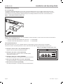
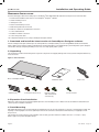
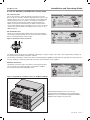
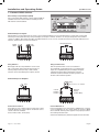
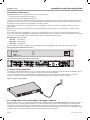
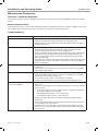
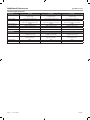
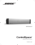
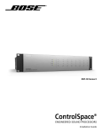
ESP-880 ESP-1240 ESP-4120 ControlSpace ® Engineered Sound Processors Installation Guide pro.Bose.comContents Introduction.......................................................................................... 12 Online Resources.................................................................................................................................... 12 Product Features..................................................................................................................................... 12 Available Accessories............................................................................................................................ 13 Accessory Cards..................................................................................................................................... 13 User Control Interfaces............................................................................................................................ 13 Product Overview.................................................................................. 14 Front Panel................................................................................................................................................ 14 Rear Panel................................................................................................................................................. 14 Front Panel LED Indicators.................................................................................................................. 14 Hardware Installation............................................................................ 15 1. Download and install the latest version of ControlSpace® Designer™ software............ 15 2. Unpacking............................................................................................................................................. 15 3. Expansion Card Installation............................................................................................................ 15 4. Rack-Mounting................................................................................................................................... 15 5. Analog Audio Connections............................................................................................................. 16 6. CC-16, RS-232, and ESPLink connections............................................................................... 17 CC-16 Connector.................................................................................................................................... 17 RS-232 Connector................................................................................................................................... 17 ESPLink Connector................................................................................................................................. 17 7. Connect GPIO devices..................................................................................................................... 18 General Purpose Inputs........................................................................................................................... 18 General Purpose Outputs........................................................................................................................ 18 8. Network Connections ...................................................................................................................... 19 9. Power Cord Connection.................................................................................................................. 19 10. Configuration with ControlSpace Designer Software.......................................................... 19 Maintenance Operations......................................................................... 20 Firmware / Software Upgrades........................................................................................................... 20 Battery Replacement............................................................................................................................. 20 Troubleshooting....................................................................................................................................... 20 Appendix................................................................................................ 21 Technical Specifications.......................................................................................................................... 21 Additional Resources ............................................................................ 23 English User Guide Page 3 Important Safety Information pro.Bose.com Thank you for selecting Bose® ControlSpace ESP processors for your sound reinforcement system. This document is intended to provide professional installers with basic installation and safety guidelines for Bose® ControlSpace ESP processors in typical fixed-installation systems. Please read this document before attempting installation. WARNINGS: • This product is intended for installation by professional installers only. • Do not expose this apparatus to dripping or splashing, and do not place objects filled with liquids such as vases, on or near the apparatus. As with any electronic products, use care not to spill liquids into any part of the system. Liquids can cause a failure and/or a fire hazard. • To reduce the risk of fire or electric shock, do not expose this apparatus to rain or moisture. • Do not place any naked flame sources, such as lighted candles, on or near the apparatus. • To prevent electric shock, match the wide blade of the line cord plug to the wide slot of the AC (mains) receptacle. Insert fully. CAUTIONS: • This product shall be connected to a mains socket outlet with a protective earthing connection. • Use of controls or adjustments or performance of procedures other than those specified herein may result in hazardous radiation exposure. The product should not be adjusted or repaired by anyone except properly qualified service personnel. • Make no modifications to the system or accessories. Unauthorized alternations may compromise safety, regulatory compliance, and system performance. NOTES: • • • • The product must be used indoors. It is neither designed nor tested for use outdoors, in recreational vehicles, or on boats. Where the mains plug or appliance coupler is used as the disconnect device, such disconnect device shall remain readily operable. See the additional instructions on the Important Safety Instructions sheet (North America only) enclosed in the shipping carton. Provide an earth connection before the main plug is connected to the mains. The lightning flash with arrowhead symbol, within an equilateral triangle, is intended to alert the user to the presence of uninsulated dangerous voltage within the system enclosure that may be of sufficient magnitude to constitute a risk of electrical shock. The exclamation point within an equilateral triangle, as marked on the system, is intended to alert the user to the presence of important operating and maintenance instructions in this installation guide. Important Safety Instructions 1. Read these instructions. 2. Keep these instructions – for future reference. 3. Heed all warnings – on the product and in the owner’s guide. 4. Follow all instructions. 5. Do not use this apparatus near water or moisture. 6. Clean only with a dry cloth. 7. Do not block any ventilation openings. Install in accordance with the manufacturer’s instructions. To ensure reliable operation of the product and to protect it from overheating, put the product in a position and location that will not interfere with its proper ventilation. 8. Do not install near any heat sources, such as radiators, heat registers, stoves, or other apparatus (including amplifiers) that produce heat. 9. Do not defeat the safety purpose of the polarized or grounding-type plug. A polarized plug has two blades with one wider than the other. A grounding-type plug has two blades and a third grounding prong. The wider blade or third prong are provided for your safety. If the provided plug does not fit in your outlet, consult an electrician for replacement of the obsolete outlet. 10. Protect the power cord from being walked on or pinched, particularly at plugs, convenience receptacles, and the point where they exit from the apparatus. 11. Only use attachments/accessories specified by the manufacturer. Page 4 Installation and Safety Guidelines English pro.Bose.comImportant Safety Information 12. Use only with the cart, stand, tripod, bracket, or table specified by the manufacturer or sold with the apparatus. When a cart is used, use caution when moving the cart/apparatus combination to avoid injury from tip-over. 13. Unplug this apparatus during lightning storms or when unused for long periods of time to prevent damage to this product. 14.Refer all servicing to qualified service personnel. Servicing is required when the apparatus has been damaged in any way such as powersupply cord or plug is damaged; liquid has been spilled or objects have fallen into the apparatus; the apparatus has been exposed to rain or moisture, does not operate normally, or has been dropped. Do not attempt to s ervice this product yourself. Opening or removing covers may expose you to dangerous voltages or other hazards. Please call Bose to be referred to an authorized service center near you. 15. To prevent risk of fire or electric shock, avoid overloading wall outlets, extension cords, or integral convenience receptacles. 16. Do not let objects or liquids enter the product – as they may touch dangerous voltage points or short-out parts that could result in a fire or electric shock. 17. See product enclosure for safety related markings. 18. No naked flame sources, such as lighted candles, should be placed on the apparatus. 19. The mains plug is used to disconnect the device and it shall remain readily operable. To completely disconnect the power input, the mains plug of the apparatus shall be disconnected from the mains. 20. The POWER indicator LED will illuminate green when the product has mains power. If power is applied and the LED is not illuminated, or if the LED is red, please send the unit for service. Bose Corporation hereby declares that this product is in compliance with the essential requirements and other relevant provisions of Directive 1999/5/EC and all other applicable EU directive requirements. The complete declaration of conformity can be found at: www.Bose.com/compliance. This product meets the immunity requirements for the E2 class EN55103-2 directive. Inrush current at cold start, 230V: 9.47A Inrush current after interruption for 5 sec, 230V: 41.16A Information about products that generate electrical noise If applicable, this equipment has been tested and found to comply with the limits for a Class B digital device, pursuant to Part 15 of the FCC rules. These limits are designed to provide reasonable protection against harmful interference in a residential installation. This equipment generates, uses, and can radiate radio frequency energy and, if not installed and used in accordance with the instructions, may cause harmful interference to radio communications. However, this is no guarantee that interference will not occur in a particular installation. If this equipment does cause harmful interference to radio or television reception, which can be determined by turning the equipment off and on, you are encouraged to try to correct the interference by one or more of the following measures: • Reorient or relocate the receiving antenna. • Increase the separation between the equipment and receiver. • Connect the equipment to an outlet on a different circuit than the one to which the receiver is connected. • Consult the dealer or an experienced radio/TV technician for help. This product complies with the Canadian ICES-003 Class B specifications. General precautions CAUTION: Place the unit where it will be protected from heat and allow adequate ventilation. Place the unit away from direct heat sources, such as heating vents and radiators. Make sure the air can circulate freely behind, beside and above the unit. Do not allow the chassis to exceed the maximum operating temperature of 50˚C. Be aware of conditions in an enclosed rack that may increase the temperature above room ambient conditions. CAUTION: Be sure all the fine strands of the wire are twisted together and contained within the connector. If even one strand is loose and can touch the adjacent terminal, a short circuit may occur. The information furnished in this guide does not include all of the details of design, production, or variations of the equipment. Nor does it cover every possible situation which may arise during installation, operation, or maintenance. If you need assistance beyond the scope of this installation guide, please contact our Customer Service department. English Installation and Safety Guidelines Page 5 Installation and Operating Guide pro.Bose.com Introduction Thank you for choosing the Bose® ControlSpace® ESP-880/1240/4120 engineered sound processors. Bose ControlSpace ESP-880, ESP-1240, and ESP-4120 engineered sound processors are single-rack-space DSPs, available in analog I/O configurations of 8 x 8, 12 x 4, and 4 x 12. These cost-effective models meet today’s strict requirements for low latency audio processing with high-quality digital conversion and powerful DSP. Bose® ControlSpace® Designer™ software, available as a free download from pro.Bose.com, enables PC setup, control, and monitoring of Bose ControlSpace ESP processors, controls, and PowerMatch® power amplifiers over standard Ethernet networks. Details on making a network connection to ESP processors can be found on page 19. This document delivers basic installation information. A separate document, the ControlSpace Designer Software Guide can be downloaded as a PDF from pro.Bose.com or can be found inside the ControlSpace Designer software help system. The information furnished in this guide is intended to help you install and set up the product, but does not include all details of design, production, or variations of the equipment. Nor does it cover every possible situation that may arise during installation, operation, or maintenance. If you need assistance beyond the scope of this guide, please contact your local Bose Representative or Technical Support specialist. (See contact information in the back of this guide.) Online Resources pro.Bose.com Main resource for product information, downloads, tech data sheets. proForum.Bose.com Register and participate in forum user groups to post questions, interface with Bose staff, and share application information on this product. Product Features • Three single-rack ESP models Choice of 8 x 8, 12 x 4 or 4 x 12 analog I/O allows for more flexibility in routing of the signal path. • High-quality analog circuitry Provides ultra-low distortion and noise (0.002% THD+N) and >115 dB analog dynamic range (A-weighted, input to output). • Advanced, open-architecture DSP 48 kHz sample rate/24-bit conversion and a fixed/floating-point DSP. Allows an open arrangement of low-latency signal processing and control functions using ControlSpace Designer software. • Front-panel RJ-45 Ethernet connection Allows localized configuration of the processor for stand-alone operation, or when used together with an optional rear-panel network card, serves as a convenient network passthrough for connection to the main control network. • Integrated Bose® ESPLink output Provides an 8-channel low-latency digital audio link to PowerMatch® amplifiers located in the same equipment rack. • Expansion card slot Supports the use of accessory cards including network control and audio transport options. • One-wire networking using expansion cards Optional audio networking cards leverage connections combining streaming audio and control on the same cable, eliminating the need for two separate network connections. • Bose ControlSpace Designer software Offers a large set of signal processing modules such as automatic microphone mixing, multiband graphic and parametric EQs, Bose loudspeaker EQ libraries, signal generators, routers, mixers, AGCs, duckers, gates, compressors, source selectors and delays. With ControlSpace Designer software it is possible to design, configure, control and monitor all Bose networked system electronics from a single software application. • A variety of control options All models are compatible with Bose CC-64 and CC-16 programmable controllers and three simplified zone volume interfaces in addition to potentiometers and switches offered by other manufacturers. • Integration with third-party control systems and remotes Built-in RS-232 serial, Ethernet, and GPIO ports provide solid integration with industry-standard control systems and third-party user controls. Page 12 User Guide English Installation and Operating Guide pro.Bose.com Available Accessories Accessory Cards ControlSpace® ESP-880/1240/4120 processors offer a rear panel digital expansion slot for adding network audio and control capabilities beyond what is available using the front panel RJ-45 connector. For systems requiring control network connections to be located on the rear panel (without streaming audio), the ControlSpace Network Control card is recommended for use. Figure 1. ControlSpace Network Control card At time of print, the following expansion cards are available. For further information on these cards, and to view new cards that are available, please visit pro.Bose.com. • ControlSpace ESP-880/1240/4120 Network Control card PC 359841-0010 • ControlSpace ESP-880/1240/4120 Dante network card PC 359842-0020 ™ User Control Interfaces ESP-880/1240/4120 processors are compatible with Bose® programmable controllers and three types of simplified volume/zone controls. The following interfaces can be used with the ESP-880/1240/4120 engineered sound processors: Figure 2. ControlSpace® CC-64 control center • ControlSpace CC-64 control center (PC 041760) (Figure 2) Network control of any Bose networkable hardware. • ControlSpace CC-16 zone controller (PC 041761) Uses CC-16 port. Up to 15 devices can be used with any ESP engineered sound processor. • ControlSpace CC-4 room controller (PC 042023) Uses GPI port: Requires 5 control inputs and one ground termination. • Volume Control with A/B switch user interface (PC 041967) Uses GPI port: Requires 2 control inputs and one ground termination. • Volume Control user interface (PC 041966) Uses GPI port: Requires 1 control input and one ground termination. 12 English User Guide Page 13 Installation and Operating Guide pro.Bose.com Product Overview Front Panel 2 1 Figure 3. Front Panel View 1. LED Indicators: Power, Signal, Ethernet and Serial indication. (See “Front Panel LED Indicators” below.) 2. Ethernet Connector: RJ-45 jack for front panel network connectivity. (See “Network Connections” on page 19.) Rear Panel Figure 4. Rear Panel View 1 2 3 9 5 4 8 6 7 1. Analog audio connectors: Mic/line-level balanced input and line-level output connectors. (See “Analog Audio Connections” on page 16.) 2. ESPLink output connector: For use with ESPLink-equipped PowerMatch® amplifiers. 3. Chassis serial number. 4. RS-232: 5-wire, RS-232 (DTE) serial interface connection. (See “RS-232 Connector” on page 17.) 5. Digital expansion slot: Supports optional digital expansion cards. 6. AC Mains receptacle: Power cord connection. (IEC 60320-C14 inlet). 7. CC-16 connector: RS-485 network connection for up to 15 Bose CC-16 zone controllers. (See “CC-16 Connector” on page 17.) 8. Control Outputs connector: Five general-purpose control outputs. (See “General Purpose Outputs” on page 18.) 9. Control Inputs connector: Five general-purpose inputs. (See “General Purpose Inputs” on page 18.) Front Panel LED Indicators POWER Power, booting, or fault-state indication • Green: Power on, normal operation • Yellow: Booting • Red: Fault error (See “Troubleshooting” on page 20.) SIGNAL Prioritized signal status indication of all audio input and output channels, listed by order of signaling priority. For precise metering and gain control, connect using ControlSpace® Designer™ software. • Green: Signal present on one or more channels • Yellow: Signal level optimal (-20 dBFS to -2 dBFS) on one or more channels • Red: Clipping (> -2 dBFS) found on one or more channels ETHERNET Connection status indication of front panel and/or option card Ethernet ports. • Green: Link established • Yellow: Tx/Rx activity SERIAL RS-232 and CC-16 serial command status indication. • Green: CC-16 controller command transmitted • Yellow: CC-16 controller command received • Red: RS-232 Rx/Tx activity Page 14 User Guide English Installation and Operating Guide pro.Bose.com Hardware Installation Use the following procedure when setting up a ControlSpace® ESP-880/1240/4120 engineered sound processor for the first time. 1. Download and install the latest version of ControlSpace® Designer™ software 2. Unbox the ESP processor 3. Install option card 4. Rack-mount the ESP processor 5. Make analog audio I/O connections 6. Make CC-16, RS-232, and ESPLink connections 7. Connect GPIO devices 8. Establish a network connection 9. Connect the power cable 10. Configure the ESP processor using ControlSpace Designer software 1. Download and install the latest version of ControlSpace Designer software Install ControlSpace Designer software prior to working with the ControlSpace ESP processor. Visit pro.Bose.com to download the latest software version which includes product firmware, the latest algorithms, and a detailed help system that guides system designers and installers through configuring the ESP processor for use in high-quality audio systems. 2. Unpacking The product box includes the following items. Inspect all components for shipping damage and contact your Bose Representative if any issues are found. Figure 5. Carton Contents Bose® ControlSpace® ESP Installation Guide 1 Cable ties (11) 2 3 4 5 1 2 3 4 5 Control I/O connectors (2) + – + – + – + – Phoenix Contact® dual channel audio connectors (8) Power cord AB CC-16 connector 3. Expansion Card Installation Expansion cards insert into the rear-panel digital expansion slot of the ESP processor. Refer to the documentation included with each card for specific installation instructions. 4. Rack-Mounting ESP-880/1240/4120 processors are designed to fit standard 19-inch (48 cm) rack equipment, occupying 1 rack-unit (RU) in height, and requiring a mounting depth of 8.2 inches (208 mm) from the front rack rail. Use four fasteners with washers (not supplied) to mount the processor. The product uses passive (fan-less) side ventilation and can safely operate in ambient conditions from 32°F - 122°F (0°C - 50°C). Refer to page 21 for power dissipation ratings. English User Guide Page 15 Installation and Operating Guide pro.Bose.com 5. Analog Audio Connections The ESP processor includes balanced dual-channel (6-terminal) Phoenix Contact® audio connectors. To help with ease of installation, the termination end of each connector includes printed terminal block descriptions. The following diagram shows recommended balanced/unbalanced wiring between the processor audio connectors and common audio plugs used to connect the ESP processor to external audio components. Figure 6. Wiring Balanced and Unbalanced Devices Source Device Connector Phoenix Contact® Input Connector T S S RCA T XLR 1 2 3 Phone Plug (Balanced) Phone Plug (Unbalanced) 1 T R S T Page 16 User Guide 2 3 S T R S T S English Installation and Operating Guide pro.Bose.com 6. CC-16, RS-232, and ESPLink connections CC-16 Connector The CC-16 connector is an RS-485 network connection for use with Bose CC-16 zone controllers. Using the supplied Phoenix Contact® 3-pin labeled connector, up to 15 CC-16 zone controllers can be networked to control the ESP processor or any device on the Bose® ControlSpace® control network. An external power supply is required. Note that in addition to wiring the A and B terminals, it is highly recommended to connect the ground terminal from the ESP processor to each CC-16 zone controller. The maximum distance from ESP processor to any CC-16 is 2000 feet (610 m). RS-232 Connector The RS-232 connector provides a DB-9 male connector (type DTE) for communication between the ESP processor and other serial-controlled devices including third-party control systems. Figure 7. RS-232 Panel Connector Pinout The default serial port settings are 115,200 baud, 8-bits length, 1 stop bit, no parity, and no flow control. If required these settings can be changed using ControlSpace® Designer™ software. The document ControlSpace® Serial Control Protocol (downloadable from pro.Bose.com) outlines all supported command strings and functions available to control/query Bose ESP processors and PowerMatch® power amplifiers. ESPLink Connector The ESPLink connector provides a low-latency method for transporting up to 8 channels of uncompressed audio to PowerMatch® amplifiers. For use with standard optical (TOSLINK™) cables. Figure 8. Using ESPLink to distribute audio to PowerMatch amplifiers An ESP-880/1240/4120 processor can serve as a centralized input routing/mixing point for simplified audio distribution to one or more ESPLink-equipped PowerMatch amplifiers when installed in the same rack. English User Guide Page 17 Installation and Operating Guide pro.Bose.com 7. Connect GPIO devices General Purpose Inputs/Outpus (GPIO) Five control inputs (GPI) and five controls outputs (GPO) are available and can be used to interface the ESP processor with external control hardware. General Purpose Inputs General-purpose control input ports are used to connect external hardware such as potentiometers (to control levels or gains) and switches (to invoke parameter sets). Using ControlSpace® Designer™ software, functions can easily be assigned to these external controls. In addition, Bose offers three GPI-compatible interfaces, the CC-4 room controller, the Volume Control with A/B switch user interface, and the Volume Control user interface. 10k potentiometer Push button Toggle switch Using Switches Using Potentiometers Both toggle switches and pushbuttons can be used with control inputs. Each input terminal is tied to an internal pull-up resistor (2k ohm) so that external switches can be wired directly from input to ground. 10k ohm potentiometers can be connected and associated with control gain blocks in a system design. Inputs are compatible (through ControlSpace Designer software) with linear taper potentiometers wired for minimum resistance at the full-clockwise position or at the full-counterclockwise position. General Purpose Outputs Relay LED Anode Cathode (Rated Current of Coil <100 Current Limiting Resistor mA External Supply (24 VDC Max.) Current Source Devices Current Sink Devices Some devices such as LEDs and low-current relays can be powered directly from control outputs. A maximum source current of 10 mA is available. Devices that require more current than is available from a currentsource configuration can use control outputs to sink up to 100mA when used with external power supplies. Use proper precautions when driving inductive loads. Source Limits: 8 VDC, 10 mA (max.). Page 18 User Guide Sink Limits: 100 mA (max.). External supplies must be ≤24 VDC. English pro.Bose.com Installation and Operating Guide 8. Network Connections ESP-880/1240/4120 processors feature two network connection methods: 1. A front-panel RJ-45 network port (See figure 9.) 2. Optional rear-panel network cards (See figure 10.) The front-panel connection is intended for localized configuration and monitoring. When used with a rear-panel network card, the frontpanel RJ-45 connector can serve as a convenient passthrough to the network connection on the rear panel. For added security, the front panel connector is lockable using ControlSpace® Designer™ software. Network option cards can serve as the primary means for configuration, control, and monitoring of an ESP through connection to a larger network. Note: When using a rear-panel network card, do not plug both the front and rear-panel RJ-45 connections into a common network switch or router. Use a F/UTP Cat5e cable (not supplied) to connect a PC to the ESP processor. This connection can be made either directly to the processor or through a switched Ethernet network. Once powered, the ESP processor will try to retrieve an IP address from an available server. If unsuccessful, the ESP processor will timeout and revert to a default IP address as below: Default IP addresses per model: ESP-880: 192.168.0.161 ESP-1240: 192.168.0.162 ESP-4120: 192.168.0.163 For more information, see the ControlSpace Designer Software Guide from pro.Bose.com or inside the software help system. Figure 9. Front Panel Network Port Location Figure 10. Optional Rear Panel Network Card Location 9. Power Cord Connection ControlSpace® ESP-880/1240/4120 processors can operate with AC mains line voltages from 85 to 264 volts AC at 50/60 Hz and uses a removable IEC power cord. Power consumption is less than 15VA at 122ºF (50ºC) ambient. To power on the ESP processor, simply plug in the rear-panel IEC power cord. Once powered, boot times may be as long as 40 seconds. A solid green Power LED on the front panel indicates that the processor is ready for connection/operation. Figure 11. Power cord connection 10. Configuration with ControlSpace Designer Software With a network connection in place and ControlSpace Designer software installed, use the Update Firmware tool inside ControlSpace Designer software to scan and update the ESP processor. Once the ESP processor status reads "Up-to-Date" in the firmware panel, proceed with your system design using ControlSpace Designer software. For full details on using ControlSpace Designer software to configure, control, and monitor the ESP processor or entire systems built with Bose networked system electronics, visit pro.Bose.com and download the ControlSpace Software Guide or use the help system inside the software. English User Guide Page 19 Installation and Operating Guide pro.Bose.com Maintenance Operations Firmware / Software Upgrades ControlSpace® Designer™ software is updated on a periodic basis. Please check our website at pro.Bose.com for new software releases. Battery Replacement Single-rack ESP processors contain a replaceable lithium battery for maintaining the real time clock (RTC) capability of the system. These batteries last at least 10 years from time of production and usually do not require replacement. Troubleshooting No Power LED activity on front panel • Plug in IEC power cord, check mains power Power is on, but no sound • Verify that there is an input signal from the source using ControlSpace Designer software. The audio input metering should be in the green/yellow band. • Verify that there is an output signal. The audio output signal metering should be in the green/yellow band. Sound is distorted • Using ControlSpace Designer software, verify that the audio input signal indicator blocks are not showing solid red or flashing red. If they are, reduce the input pre-gain setting to where the input is not longer clipping (red). • Using ControlSpace Designer software, verify that the audio output signal indicator blocks are not solid red or flashing red. If they are, and the input indicators are green, use the Designer software to reduce the output gain or any intermediary gain in the signal path. • If the input source signal is clean when it enters the ESP system, and the input and output indicators are green, verify that the loudspeakers are not being overdriven and are not damaged. Power LED is Red • DSP configuration not loaded. Use ControlSpace Designer software to load a configuration. • Power-cycle the unit using the power cord. If the issue continues, call your Bose Sales/Support representative. Ethernet LED is off • Verify that the ESP LAN port is connected to a PC. • Verify that the Ethernet LAN connection on the PC is enabled. If it is not enabled, the Link LED on the PC will probably be off. • If connected to a hub or switch, check that device's Link LED. • If using a rear-panel network card, unplug the ESP and try reseating the card. Ethernet LED is on but cannot communicate with ESP • Ensure that the ESP processor is fully booted. The Power LED should be a solid green color. • Verify that the LAN settings on the TCP/IP Ethernet device you are using on the PC are set correctly: - If not using a DHCP server, the IP address of the PC should be set manually to an unused IP address (e.g. 192.168.0.2). - The default IP Subnet mask is set to 255.255.255.0. - Check firewall settings on the PC, unblock all ports. • Verify that the proper NIC card is selected in ControlSpace Designer software network tool. • If using a rear-panel network card, make sure the front-panel network connection is not plugged into the same network. • Verify that there is not another ESP connected with the same address. If unsure, disconnect one, scan for the remaining unit, and change its address. Repeat with the second unit. Page 20 User Guide English pro.Bose.comAppendix Appendix Technical Specifications Integrated DSP ESP-880, ESP-1240, ESP-4120 Signal Processor 32-bit fixed/floating-point DSP + ARM, 456 MHz Maximum Calculation Delay Audio Latency 3.6 GIPS / 2.7 GFLOPS 43 s 860 μs (analog in to analog out) A/D and D/A Converters 24-bit Sample Rate 48 kHz Audio Performance Specifications Frequency Response THD+N Channel Separation (Crosstalk) Dynamic Range 20 Hz - 20 kHz (+0.3 dB/-0.1 dB) 0.002 % at +4 dBu (A-weighted/20 Hz – 20 kHz) < -105 dB at +4 dBu input and output level, 1 kHz > 115 dB, A-weighted 20 Hz – 20 kHz, analog input to analog output Control Inputs Inputs (Control) 5 analog or digital inputs, 2 kΩ internal pull-up resistor to 5 V, 3.81 mm Phoenix Contact®, 6-pin Analog Input Voltage Range 0 V to 3.3 V (maximum 5 V) Digital Input Voltage Range 0 V to 3.3 V (threshold voltage = 1.6 V) Control Outputs Outputs (Control) Output Voltage 5 digital outputs, 3.81 mm Phoenix Contact®, 6-pin High: 8 V (open circuit), 2.5 V @ 10 mA Low: < 1 V @ 100 mA, push-pull Indicators and Controls LED Status Indicators Power/Status, Signal, Ethernet, Serial (RS-232 + CC-16) Audio Signal Indication Green (-60 to -25 dBFS), Yellow (-24 to -3 dBFS), Red (-2 dBFS to Clip) Electrical Specifications Mains Voltage AC Power Consumption 85 VAC-264 VAC 50/60 Hz < 15VA typical at 122 °F (50 °C) ambient Mains Connector IEC 60320-C14 (Inlet) Power Dissipation 12 W (41 BTU, 10 kcal) Physical Dimensions 1.7" H x 19" W x 8.5" D (44 mm x 483 mm x 215 mm) Net Weight 5.8 lb (2.6 kg) Operating Temperature Cooling System 32 °F - 122 °F (0 °C - 50 °C) Passive, side venting General PC Configuration Software Network Control Communication Ports Expansion Slots Audio Channel Capacity English ControlSpace® Designer™ software Ethernet (RJ-45), 100Mb RS-232 (DB9M, DTE), Bose CC-16 (3.81 mm Phoenix Contact®, 3-pin) 1 control/audio network 56 (16 analog, 8 ESPLink out, 16x16 digital with expansion card) Page 21 User Guide Additional Resources pro.Bose.com Technical Specifications Audio Inputs ESP-880 ESP-1240 ESP-4120 Input Channels 8 analog (balanced, mic/line level), 16 digital (via option card) 12 analog (balanced, mic/line level), 16 digital (via optional card) 4 analog (balanced, mic/line level), 16 digital (via optional card) Connectors, Input 3.81 mm Phoenix Contact®, 6-pin 3.81 mm Phoenix Contact®, 6-pin 3.81 mm Phoenix Contact®, 6-pin Input Impedance 12 kΩΩ @ 1 kHz (with or without phantom power active) 12 k Ω Ω@ 1 kHz (with or without phantom power active) 12 k Ω @ 1 kHz (with or without phantom power active) Maximum Input Level +24 dBu +24 dBu +24 dBu Equivalent Input Noise -118 dB at 48 dB gain setting -118 dB at 48 dB gain setting -118 dB at 48 dB gain setting +48 VDC, 10 mA, selectable per input +48 VDC, 10 mA, selectable per input +48 VDC, 10 mA, selectable per input 0/14/24/32/48/54/64 dB 0/14/24/32/48/54/64 dB 0/14/24/32/48/54/64 dB Output Channels 8 analog (balanced, line level), 8 ESPLink, 16 digital (via option card) 4 analog (balanced, line level), 8 ESPLink, 16 digital (via optional card) 12 analog (balanced, line level), 8 ESPLink, 16 digital (via optional card) Connectors 3.81 mm Phoenix Contact®, 6-pin (analog), EIAJ optical (ESPLink) 3.81 mm Phoenix Contact®, 6-pin (analog), EIAJ optical (ESPLink) 3.81 mm Phoenix Contact®, 6-pin (analog), EIAJ optical (ESPLink) Phantom Power Gain settings Audio Outputs Output Impedance Maximum Output Level Page 22 User Guide 200 Ω 200 Ω 200 Ω +24 dBu +24 dBu +24 dBu English pro.Bose.com Additional Resources Additional Resources Visit us on the web at pro.Bose.com for more information, including specifications, technical literature, product warranty, parts and accessories, and global support contact information. Americas (USA, Canada, Mexico, Central America, South America) Bose Corporation The Mountain Framingham, MA 01701 USA Corporate Center: 508-879-7330 Americas Professional Systems, Technical Support: 800-994-2673 Australia Bose Pty Limited Unit 3/2 Holker Street Newington NSW Australia 61 2 8737 9999 Belgium Bose N.V. / S.A Limesweg 2, 03700 Tongeren, Belgium 012-390800 China Bose Electronics (Shanghai) Co. Ltd. 36F, West Gate Tower 1038 West Nanjing Road Shanghai, P.R.C. 200041 China 86 21 6271 3800 France Bose S.A.S 12 rue de Temara 78100 St. Germain-en-Laye, France 01-30616363 Germany Bose GmbH Max-Planck Strasse 36D 61381 Friedrichsdorf, Deutschland 06172-7104-0 Hong Kong Bose Limited Suites 2101-2105, Tower One, Times Square 1 Matheson Street, Causeway Bay, Hong Kong 852 2123 9000 India Bose Corporation India Private Limited 4th Floor, Shriram Bhartiya Kala Kendra 1, Copernicus Marg New Delhi 110001, India 91 11 23073825 Italy Bose SpA Via Della Magliana 87600148 Rome, Italy 066-5670802 Japan Bose Kabushiki Kaisha Sumitomo Fudosan Shibuya Garden Tower 5F 16-17, Nanpeidai-cho Shibuya-Ku, Tokyo, 150-0036, Japan TEL 81-3-5489-0955 www.bose.co.jp The Netherlands Bose BV Nijverheidstraat 8 1135 GE Edam, Nederland 0299-390139 United Kingdom Bose Ltd 1 Ambley Green, Gillingham Business Park KENT ME8 0NJ Gillingham, England 0870-741-4500 See website for other countries. English Page 23 User Guide © 2013 Bose Corporation. All rights reserved. The Mountain, Framingham, MA 01701-9168 USA www.pro.Bose.com All trademarks are the property of their respective owners. AM372643 Rev. 00