1
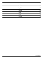
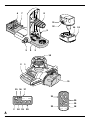
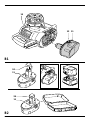
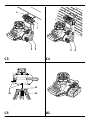
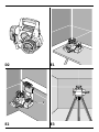
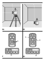
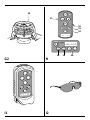
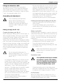
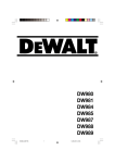
®
DW077
1
Dansk
11
Deutsch
21
English
33
Français
43
Norsk
54
Suomi
64
Svenska
74
Copyright DEWALT
2
6
7
8
11
12
14 13
9
5
4
3
10
2
1
11
15 16 17
21
20
19
22
1
18 19
18
20
A
3
15
12 11
B1
24
11
24
11
B2
4
25
B3
B4
A
B
6
C1
7
26
27
4
8
C2
5
6
7
3
4
C3
3
C4
29
30
C5
6
28
D1
4
D2
E1
9
E2
E3
7
E4
E5
21
20
19
F
8
19
G1
20
10
21
20
19
18
18
G2
H
I1
I2
19
20
9
I3
10
I4
ENGLISH
ROTARY LASER DW077
Congratulations!
EC-Declaration of conformity
You have chosen a DEWALT tool. Years of
experience, thorough product development and
innovation make DEWALT one of the most reliable
partners for professional power tool users.
Technical data
Voltage
V
Rotary speed
min-1
Laser class
Protection class
Self-leveling range
°
Operating temperature
°C
Receptacle thread
Weight (without battery pack) kg
DW077
9.6/12/14.4/18
0/10/80/280/800
II
IP54
+/- 5
-5 - +45
5/8" x 11
2.5
DW077
DEWALT declares that these tools have been
designed in compliance with: 73/23/EEC, 98/37/EEC,
89/336/EEC, EN 60335, EN 55014-1, EN 55014-2,
EN 61000-3-2, EN 61000-3-3, EN 60825-1 &
EN 61010-1.
For more information, please contact DEWALT at the
address below or refer to the back of the manual.
DW077
LpA(sound pressure)
Weighted RMS acceleration value
dB(A)*
< 70
m/s2
< 2.5
* at the operator’s ear
Battery pack
Battery type
Voltage
Weight
Charger
Mains voltage
Approx. charging time
Weight
V
kg
VAC
min
kg
DE9095
NiCd
18
1.1
DE9108
230
60
0.4
DE9039
NiMH
18
1.1
DE9116
230
60
0.4
TÜV Rheinland
Product and Safety GmbH (TRPS)
Am Grauen Stein 1
D-51105 Köln
Germany
Cert. No.
21103197 001
Fuses:
Europe
230 V tools
U.K. & Ireland 230 V tools
10 Amperes, mains
13 Amperes, in plugs
Director Engineering and Product Development
Horst Großmann
The following symbols are used throughout this
manual:
Denotes risk of personal injury, loss of life
or damage to the tool in case of nonobservance of the instructions in this
manual.
Denotes risk of electric shock.
DEWALT, Richard-Klinger-Straße 40,
D-65510, Idstein, Germany
Fire hazard.
33
ENGLISH
Safety instructions
When using power tools, always observe the
safety regulations applicable in your country to
reduce the risk of fire, electric shock and
personal injury.
Read all of this manual carefully before operating
the tool. Also refer to the manual of any power
tool that will be used with this tool.
Save this manual for future reference.
General
1 Keep work area clean
Cluttered areas and benches can cause
accidents.
2 Consider work area environment
Do not expose power tools to humidity. Keep
work area well lit. Do not use power tools in the
presence of flammable liquids or gases.
3 Guard against electric shock
Prevent body contact with earthed surfaces (e.g.
pipes, radiators, cookers and refrigerators).
For use under extreme conditions (e.g. high
humidity, when metal swarf is being produced,
etc.) electric safety can be improved by inserting
an isolating transformer or a (FI) earth-leakage
circuit-breaker.
4 Keep children away
Do not let children come into contact with the
tool or extension cord. Supervision is required for
those under 16 years of age.
5 Use appropriate tool
The intended use is described in this instruction
manual. Do not force small tools or attachments
to do the job of a heavy-duty tool. The tool will
do the job better and safer at the rate for which it
was intended.
Warning! The use of any accessory or attachment
or performance of any operation with this tool,
other than those recommended in this instruction
manual may present a risk of personal injury.
6 Maintain tools with care
Keep the tools in good condition and clean for
better and safer performance. Follow the
instructions for maintenance and changing
accessories. Inspect the tool cords at regular
intervals and, if damaged, have them repaired by
an authorized DEWALT repair agent. Keep all
controls dry, clean and free from oil and grease.
34
7 Store idle tools
When not in use, power tools must be stored in a
dry place and locked up securely, out of reach of
children.
8 Check for damaged parts
Before using the tool, carefully check it for
damage to ensure that it will operate properly
and perform its intended function. Check for
misalignment and seizure of moving parts,
breakage of parts and any other conditions that
may affect its operation. Have damaged guards
or other defective parts repaired or replaced as
instructed.
Do not use the tool if the switch is defective.
Have the switch replaced by an authorized
DEWALT repair agent.
9 Remove the batteries
Remove the batteries when not in use, before
servicing and when changing accessories.
10 Have your tool repaired by an authorized
DEWALT repair agent
This power tool is in accordance with the relevant
safety regulations. To avoid danger, electric
appliances must only be repaired by qualified
technicians.
Additional safety instructions for rotary lasers
• This laser complies with class 2 according to
EN 60825-1:1994+A11. Do not replace a laser
diode with a different type. If damaged, have the
laser repaired by an authorised repair agent.
• Do not use the laser for any purpose other than
projecting laser lines.
An exposure of the eye to the beam of a class
2 laser is considered safe for a maximum of
0.25 seconds. Eyelid reflexes will normally
provide adequate protection. At distances over
1 m, the laser complies with class 1 and thus is
considered completely safe.
• Never look into the laser beam directly and
intentionally.
• Do not use optical tools to view the laser beam.
• Do not set up the tool at a position where the
laser beam can cross any person at head height.
• Do not let children come in contact with the
laser.
ENGLISH
Additional safety instructions for battery packs
Fire hazard! Avoid metal short circuiting
the contacts of a detached battery pack.
Do not store or carry the battery pack
without the battery cap placed over the
contacts.
• The battery fluid, a 25-30% solution of potassium
hydroxide, can be harmful. In case of skin
contact, flush immediately with water. Neutralize
with a mild acid such as lemon juice or vinegar.
In case of eye contact, rinse abundantly with
clean water for at least 10 minutes. Consult a
physician.
• Never attempt to open a battery pack for any
reason.
Labels on charger and battery pack
In addition to the pictographs used in this manual,
the labels on the charger and the battery pack show
the following pictographs:
Have defective cords replaced
immediately
+40 ˚c
+4 ˚c
Charge only between 4 °C and 40 °C
Discard the battery pack with due care
for the environment
Do not incinerate the battery pack
Labels on tool
The following pictograms are shown on the tool:
Read the instruction manual before use
Laser warning
100%
Battery charging
Safety warning: class 2 laser
100%
Battery charged
Package contents
Battery defective
Do not probe with conductive objects
Do not charge damaged battery packs
The package contains:
1 Rotary laser
1 Wall mount
1 Remote control
1 Target card
1 Pair of glasses
1 Kitbox
1 Charger
1 Battery pack
1 Instruction manual
Read instruction manual before use
Use only with DEWALT battery packs,
others may burst, causing personal injury
and damage
Do not expose to water
• Take the time to thoroughly read and understand
this manual prior to operation.
Description (fig. A)
The rotary laser DW077 has been designed to
project laser lines to aid in professional applications.
The tool can be used both inside and outside for
horizontal (level) and vertical (plumb) alignment.
35
ENGLISH
The tool can also produce a stationary laser dot that
can be directed manually to establish or transfer a
mark. The applications range from drop-ceiling
installation and wall layout to foundation leveling and
deck building.
The tool accepts DEWALT battery packs of 9.6, 12,
14.4 and 18 V.
1 On/off switch
2 Carrying handle
3 Leveling knob
4 Wall mount
5 Rack pinion locking knob
6 Wall mount clamp
7 Wall mount clamp lock
8 Fitting handle
9 Rack pinion wheel
10 Rotary laser head
11 Battery pack
Charger
Your DE9108 charger accepts DEWALT NiCd
battery packs ranging from 7.2 V to 18 V.
Your DE9116 charger accepts DEWALT NiCd and
NiMH battery packs ranging from 7.2 V to 18 V.
11 Battery pack
12 Release buttons
13 Charger
14 Charging indicator (red)
Display
15 Power indicator
16 Leveling indicator (X-axis)
17 Leveling indicator (Y-axis)
18 Scan mode activation key
19 Rotation speed setting key
20 Adjustment keys left/right
Initiated as the tool is switched on, the self-leveling
feature will level the laser head in the described tool
set-ups at ranges up to +/- 5°.
Electrical safety
The electric motor has been designed for various
voltages (see technical data). Always check that the
battery pack power corresponds to the voltage on
the rating plate. Also make sure that the voltage of
your charger corresponds to that of your mains.
Your DEWALT charger is double
insulated in accordance with EN 60335.
Mains plug replacement
(U.K. & Ireland only)
• Should your mains plug need replacing and you
are competent to do this, proceed as instructed
below. If you are in doubt, contact an authorized
DEWALT repair agent or a qualified electrician.
• Disconnect the plug from the supply.
• Cut off the plug and dispose of it safely; a plug
with bared copper conductors is dangerous if
engaged in a live socket outlet.
• Only fit 13 Amperes BS1363A approved plugs
fitted with the correctly rated fuse (1).
• The cable wire colours, or a letter, will be marked
at the connection points of most good quality
plugs. Attach the wires to their respective points
in the plug (see below). Brown is for Live (L) (2)
and Blue is for Neutral (N) (4).
• Before replacing the top cover of the mains plug
ensure that the cable restraint (3) is holding the
outer sheath of the cable firmly and that the two
leads are correctly fixed at the terminal screws.
Remote control
18 Scan mode activation key
19 Rotation speed setting key
20 Adjustment keys left/right
21 Adjustment keys up/down
22 Manual adjustment key
Self-leveling feature
The self-leveling feature realises a quick adjustment of the
rotary laser head in both level and plumb applications.
36
Never use a light socket.
Never connect the live (L) or neutral (N)
wires to the earth pin marked E or .
ENGLISH
Using an extension cable
An extension cord should not be used unless
absolutely necessary. Use an approved extension
cable suitable for the power input of your charger
(see technical data). The minimum conductor size is
1 mm2; the maximum length is 30 m.
Assembly and adjustment
• Prior to assembly and adjustment,
always remove the battery pack.
• Always switch off the tool before
inserting or removing the battery pack.
• Use only DEWALT battery packs and
chargers.
Reinsert the battery pack or try a new one. If the
new pack also refuses to charge, have your charger
tested by an authorized DEWALT repair agent.
• When plugged into power sources such as
generators or sources that convert DC to AC, the
red charging indicator may blink twice, switch off
and repeat. This indicates a temporary problem
of the power source. The charger will
automatically switch back to normal operation.
Inserting and removing the battery pack (fig. B1)
• Insert the battery pack (11) into the tool until it
clicks in place.
• To remove the battery pack, press the two
release buttons (12) simultaneously and pull the
pack out of the tool.
Battery pack (fig. A & B1 - B4)
Charging the battery pack (fig. A)
When charging the battery pack for the first time, or
after prolonged storage, it will only accept an 80%
charge. After several charge and discharge cycles,
the battery pack will attain full capacity.
Always check the mains prior to charging the battery
pack. If the mains is functioning but the battery pack
does not charge, take your charger to an authorised
DEWALT repair agent. Whilst charging, the charger
and the battery pack may become warm to touch.
This is a normal condition and does not indicate a
problem.
Do not charge the battery pack at
ambient temperatures < 4 °C or > 40 °C.
Recommended charging temperature:
approx. 24 °C.
• To charge the battery pack (11), insert it into the
charger (13) as shown and plug in the charger.
Be sure that the battery pack is fully seated in the
charger. The red charging indicator (14) will blink.
After approx. 1 hour, it will stop blinking and
remain on. The battery pack is now fully charged
and the charger automatically switches to
equalise mode. After approx. 4 hours, it will
switch to maintenance charge mode. The battery
pack can be removed at any time or left in the
connected charger indefinitely.
• The red charging indicator flashes rapidly to
indicate a charging problem.
Battery cap (fig. B2)
A protective cap is supplied to cover the contacts of
a detached battery pack. Without the protective cap
in place, loose metal objects could short circuit the
contacts, causing a fire hazard and damaging the
battery pack.
• Take off the protective cap (12) before placing
the battery pack (24) in the charger or tool.
• Place the protective cap over the contacts
immediately after removing the battery pack from
the charger or tool.
Make sure the protective cap is in place
before storing or carrying a detached
battery pack.
Equalization mode
The equalization mode helps to maintain
the optimum capacity of the battery
pack. It is therefore recommended to
use the equalization mode weekly or
every 10 charge/discharge cycles.
• Charge the battery pack as described above.
• When the charging indicator stops blinking, leave
the battery in the charger for approx. 4 hours.
Hot Pack Delay
When the charger detects a battery that is hot, it
automatically starts a Hot Pack Delay, suspending
charging until the battery has cooled.
37
ENGLISH
After the battery has cooled, the charger
automatically switches to the pack charging mode.
This feature ensures maximum battery life. The red
indicator (14) blinks long, then short while in the Hot
Pack Delay mode.
Battery type (fig. B3 & B4)
The tool is suitable for battery packs with different
voltages.
• To fit battery packs of 18 volt, rotate the adapter
plate (25) into position A.
• To fit battery packs of 9.6, 12 or 14.4 volt, rotate
the adapter plate (25) into position B.
Refer to the table in the back for a selection of
applicable battery packs.
Setting up the tool (fig. C1 - C5)
The tool facilitates various set-ups, making it useful
for several applications.
Floor set-up (fig. C1)
• Place the tool on a relatively smooth and level
surface.
• Adjust the tool for a level or plumb application.
Wall set-up (fig. C2 - C4)
The tool has been equipped with a wall mount (4) for
mounting to a wall track to aid in drop ceiling installation
and other specialty leveling projects (fig. C2).
• Fit the tool to the wall mount by inserting the
threaded pin (23) into one of the receptacles in
the tool and tightening the knob (8).
• Turn the tool on its side with the wall mount
clamp (6) in position for attachment to the wall
track (fig. C3).
• With the wall mount (4) facing the wall, turn the
wall mount clamping lock (7) in the clockwise
direction to open the clamp jaws.
• Place the clamp jaws around the wall track and
turn the wall mount clamping lock (7) in the anticlockwise direction to close the clamp jaws shut
on the track.
• Ensure that the wall mount clamping lock (7) is
securely locked.
Before attaching the tool to a wall track
ensure that the track is properly secured
to the wall.
38
• Alternatively, the tool can be hung on the wall
using the mounting holes (27) in the wall mount
(fig. C2).
- Hold the tool at the desired position against the
wall and mark the location of the two mounting
holes on the wall (fig. C4).
- Drill a hole at each of the marked locations
(required: ø 6 mm, approx. 35 mm deep).
- Insert a corresponding plug into each of the holes.
- Turn a screw into each of the plugs (required:
6 x 50 mm).
- Hang the tool on the screws.
• Adjust the leveling knob (3) to stabilise the tool
when necessary.
• Adjust the tool for a level application.
Tripod set-up (fig. C5)
The tool has been equipped with a tripod receptacle
for mounting to the DE0736 tripod (optional) or any
other tripod with the required ratings stated in the
technical data.
• Place the tripod (28) on a relatively smooth and
level surface.
• Mount the tool to the tripod by turning the
threaded pin (29) into the receptacle (30) in the
base.
• Adjust the tool for a level or plumb application.
Adjusting the tool (fig. A, D1 & D2)
The tool can be adjusted for both level (fig. D1) and
plumb (fig. D2) applications.
Self-leveling feature (fig. A)
• To initiate the leveling procedure, switch on the
tool. The leveling procedure is indicated by the
flashing of the leveling indicators (16 & 17) and
the laser beam. Once the tool has found its level
position the leveling indicators and the laser
beam will stop flashing and remain on.
• The leveling indicators and the laser beam
repeatedly flash three times rapidly to indicate
that the tool has been set up at a slope that is
beyond the self-leveling range of 5°. Switch the
tool off, re-adjust the tool set-up within the selfleveling range and switch the tool on again.
Level adjustment (fig. D1)
• Place the tool into the required position as shown.
• Switch on the tool to initiate the leveling procedure.
ENGLISH
Plumb adjustment (fig. D2)
• Place the tool into the required position as shown.
• Switch on the tool to initiate the leveling
procedure. As the leveling procedure for plumb
applications only requires adjustment of the Y axis,
only the corresponding leveling indicator (17) will
be operational.
Manually adjusting the level position (fig. A)
By using the remote control the tool can be adjusted
manually. The manual adjustment mode is
particularly useful in applications with slope angles in
both X and Y-axis.
• To activate the manual adjustment mode press the
key (22). The leveling indicators (16 & 17) go off.
• Use the keys (20) to adjust the tool in the X-axis.
• Use the keys (21) to adjust the tool in the Y-axis.
• To discontinue the manual adjustment mode,
press the key (22) again.
After discontinuing the manual leveling
mode the self-leveling feature
automatically takes over and re-adjusts
the tool to level position. The manual
adjustments will be lost immediately!
Aligning the laser line (fig. A & E1 - E5)
Level alignment
• With the tool switched on and the laser head
rotating, align the laser line with the position
mark.
• If adjustment is required, proceed as follows:
With tool in floor set-up (fig. E1):
• The tool can be placed on any sturdy object to
obtain the required height.
With tool in wall set-up (fig. E2):
• Loosen the locking knob (5) and adjust the rack
pinion wheel (9) to set the tool to the correct
position. Tighten the locking knob (5).
With tool in tripod set-up (fig. E3):
• Adjust the tripod to set the tool to the required
height.
Plumb alignment (fig. A, E4 & E5)
• With the tool switched on and the laser head
rotating, align the laser line with the position mark.
• If adjustment is required, proceed as follows:
• Use the keys (20) to move the laser head until the
laser line aligns with the position mark (fig. A).
Slope alignment (fig. A)
If the application requires the laser line to align at a
slope angle, proceed as follows:
• With the tool switched on and the laser head
rotating, activate the manual leveling mode.
• Align the laser line with the slope:
- Use the keys (20) to adjust the tool in the Xaxis.
- Use the keys (21) to adjust the tool in the Yaxis.
Instructions for use
Always observe the safety instructions
and applicable regulations.
• Always mark the center of the laser line or dot.
• To increase working distance and accuracy, set
up the tool in the middle of your working area.
• Make sure the tool has been set up securely.
• Extreme temperature changes cause movement
of internal parts that may affect the accuracy of
the tool. Regularly check the accuracy while
using the tool under these circumstances.
• Although the tool corrects small out-of-level
errors automatically, when it has registered a
bump, re-adjustment to balance or set-up may
be required.
• If the tool has been dropped or has tipped over,
have the laser head calibrated by a qualified
repair agent.
• For your own comfort, always use the remote
control to operate the tool. The remote control
not only allows you to operate the tool from a
distance, it also keeps you from touching the
tool, thereby reducing the risk of affecting the
tool’s balance and set-up.
Switching on and off (fig. A)
• To switch the tool on, press the on/off switch (1).
• To switch the tool off, press the on/off switch (1)
again.
Setting the rotation speed (fig. F)
The laser head can be set to different rotation speed
settings, thus determining the quality of the line.
39
ENGLISH
• Press the key (19). The rotation speed will cycle
from “fast” to “medium”, “slow”, “crawling” and
“stationary” each time the key is pressed.
• For a bright line, set the laser head to a slow
rotation speed.
• For a solid line, set the laser head to a fast
rotation speed.
Rotating the laser head (fig. G1 & G2)
In the stationary position, the laser head can be
moved both to the left and to the right.
Level applications:
• Use the keys (20) to move the laser head into the
required direction.
Plumb applications:
• Use the keys (21) to move the laser head into the
required direction.
Manually rotating the laser head (fig. G2)
The laser head can also be rotated manually.
• Turn the laser head (10) into the required
position.
Do not attempt to move the laser head
while it is rotating at a preset rotation
speed.
Scan mode (fig. H)
The laser head can be set to different speed settings
while moving back and forth, thus projecting a
scanning laser line.
• Press the key (18) to activate the scan mode.
The scan speed starts at “fast” rate.
• To set the scan speed press the key (19). The
scan speed will cycle from “crawling” to “slow”,
“medium” and “fast” each time the key is
pressed.
• Level applications:
- Use the keys (20) to move the scan area into
the required direction.
- Use the keys (21) to adjust the scan area.
• Plumb applications:
- Use the keys (21) to move the scan area into
the required direction.
• Press the key (18) to discontinue the scan mode.
Out-of-level alert
The out-of-level alert activates automatically 8
seconds after the leveling procedure has been
completed. Once the out-of-level alert is activated,
the tool monitors its level position continuously.
Depending on the registered level of deviation the
tool will respond to level errors as follows:
- Deviations < 2 mm over 10 m: a level error is
automatically corrected without notifying.
- Deviations 2 - 20 mm over 10 m: a level error is
automatically corrected. The laser head
temporarily stops rotating and the laser beam
starts flashing to indicate that the tool re-adjusts
to level position.
- Deviations > 20 mm over 10 m: a level error
leads to interruption of the tool’s operation. The
laser head stops rotating and the laser beam
goes off. A rapidly beeping audio signal is
produced and the on/off indicator flashes
simultaneously. To resume the operation:
• Switch the tool off. Check the balance and setup and re-adjust if required before switching
the tool on again.
Tool aids (fig. I1 - I4)
Several aids have been supplied that might be
helpful while operating the tool.
Remote control (fig. I1)
The remote control allows a manual intervention of
the self-leveling feature when slope adjustment is
required. The maximum slope angle corresponds to
the self-leveling range of the tool.
The remote control also allows you to activate the
laser line and control the laser head from distances
up to 30 m radius.
Laser enhancement glasses (fig. I2)
The red lens glasses improve the visibility of the laser
beam under bright light conditions or over long
distances. Providing best results indoors, the lens
filters out ambient light and intensifies the projected
dot or line. The glasses do not keep the laser beam
from entering the eyes.
Never look into the laser beam directly
with these glasses.
40
ENGLISH
DE0730 Target card (fig. I3)
The target card locates and marks the laser beam
as the beam crosses the card, thus enhancing the
visibility of the projected line. The laser beam passes
through the red plastic surface and is reflected by
the reflective rear side of the card. Supporting easy
use during plumb and level adjustment, the card is
marked with inch and metric scales, and has
magnets at the top to hold it to ceiling track or steel
studs.
Wall mount (fig. I4)
The wall mount may also be used as a base to
provide extra stability for the tool.
Optional accessories
Consult your dealer for further information on the
appropriate accessories.
These are:
- DE0772 Digital laser detector
- DE0734 Grade rod
- DE0736 Tripod
Battery packs
Voltage
9.6
12
14.4
18
NiCd
DE9061
DE9071
DE9091
DE9095
NiMH
DE9036
DE9037
DE9038
DE9039
Maintenance
Your DEWALT Power Tool has been designed to
operate over a long period of time with a minimum
of maintenance. Continuous satisfactory operation
depends upon proper tool care and regular cleaning.
Field calibration check
The field calibration checks must be performed
securely and accurately to make a correct diagnosis.
Whenever an error is registered, have the tool
calibrated by a qualified repair agent.
Always have the laser head calibrated by
a qualified repair agent.
Level checks
The following checks are performed to check the
calibration of laser head for level alignment.
• Place the tool in an area at about 15 m from a
vertical surface.
• With the tool in a tripod set-up, adjust the tool for
a level application.
To perform a level check of the X-axis:
• Position the tool so that the X-axis is parallel with
the vertical surface.
• Switch on the tool and rotate the head until the
laser dot appears on the vertical surface.
• Mark the centre of the laser beam. Switch off the
tool.
• Switch off the tool and rotate it 180° so that the
X-axis is parallel with the vertical surface the
other way around.
• Switch on the tool, rotate the head and once
again mark the centre of the laser dot on the
surface. Switch off the tool.
• Measure the difference between the markings.
• If the difference between the markings is 3.2 mm
or less, the laser head is properly calibrated.
• If the difference between the markings is more
than 3.2 mm, the laser head must be calibrated.
To perform a check of the Y-axis:
• Position the tool so that the Y-axis is parallel with
the vertical surface.
• Following the same procedure as described above,
mark the centre of the laser dot on the surface with
the tool in this position, after which the tool is rotated
180° to mark the centre of the laser dot once again.
• Measure the difference between the markings.
• If the difference between the markings is 3.2 mm
or less, the laser head is properly calibrated.
• If the difference between the markings is more
than 3.2 mm, the laser head must be calibrated.
Plumb check
The following check is performed to check the
calibration of laser head for plumb alignment.
• Place the tool in an area at about 1 m from a
vertical surface.
• With the tool in a floor set-up, adjust the tool for
a plumb application.
• Mark the top and bottom of the vertical surface
using a plumb bob.
• Switch on the tool and align the laser beam with
the lower marking.
• Using the remote control, move the head until the
laser beam is at the upper marking.
41
ENGLISH
• If the laser beam aligns with the top marking,
the laser head is properly calibrated.
• If the laser beam does not align with the top
marking, the laser head must be calibrated.
Cleaning
• Unplug the charger before cleaning the housing
with a soft cloth.
• Remove the battery pack before cleaning your
power tool.
• Keep the ventilation slots clear and regularly
clean the housing with a soft cloth.
• When necessary, clean the lens using a soft cloth
or a cotton bud soaked in alcohol. Do not use
any other cleaning agents.
Environment
Rechargeable battery pack
This long life battery pack must be recharged when
it fails to produce sufficient power on jobs which
were easily done before. At the end of its technical
life, discard it with due care for our environment:
• Run the battery pack down completely, then
remove it from the tool.
• NiCd and NiMH cells are recyclable. Take them
to your dealer or a local recycling station. The
collected battery packs will be recycled or
disposed of properly.
Unwanted tools
Take your tool to an authorised DEWALT repair
agent where it will be disposed of in an
environmentally safe way.
42
GUARANTEE
• 30 DAY NO RISK SATISFACTION GUARANTEE •
If you are not completely satisfied with the
performance of your DEWALT tool, simply return
it within 30 days, complete as purchased, to the
point of purchase, for a full refund or exchange.
Proof of purchase must be produced.
• ONE YEAR FREE SERVICE CONTRACT •
If you need maintenance or service for your
DEWALT tool, in the 12 months following
purchase, it will be undertaken free of charge at
an authorized DEWALT repair agent. Proof of
purchase must be produced. Includes labour and
spare parts for Power Tools. Excludes
accessories.
• ONE YEAR FULL WARRANTY •
If your DEWALT product becomes defective due
to faulty materials or workmanship within
12 months from the date of purchase, we
guarantee to replace all defective parts free of
charge or, at our discretion, replace the unit free
of charge provided that:
• The product has not been misused.
• Repairs have not been attempted by
unauthorized persons.
• Proof of purchase date is produced.
This guarantee is offered as an extra benefit
and is additional to consumers statutory rights.
For the location of your nearest authorized
DEWALT repair agent, please use the appropriate
telephone number on the back of this manual.
Alternatively, a list of authorized DEWALT repair
agents and full details on our after-sales service
are available on the Internet at www.2helpU.com.
Belgique et Luxembourg
België en Luxemburg
DEWALT
Weihoek 1, Nossegem
1930 Zaventem-Zuid
Tel:
02 719 07 11
Fax:
02 721 40 45
www.dewaltbenelux.com
Danmark
DEWALT
Hejrevang 26 B
3450 Allerød
Tlf:
70 20 15 30
Fax:
48 14 13 99
www.dewalt-nordic.com
Deutschland
DEWALT
Richard-Klinger-Straße
65510 Idstein
Tel:
06126-21-1
Fax:
06126-21-2770
www.dewalt.de
EÏÏ¿˜
BLACK & DECKER (E§§∞™) ∞.E.
™ÙÚ¿‚ˆÓÔ˜ 7 & §ÂˆÊ. µÔ˘ÏÈ·Á̤Ó˘ 159
166 74 °Ï˘Ê¿‰· - ∞ı‹Ó·
∆ËÏ.
España
DEWALT
Parque de Negocios “Mas Blau”
Edificio Muntadas, c/Bergadá, 1, Of. A6
08820 El Prat de Llobregat (Barcelona)
Tel:
Fax:
934 797 400
934 797 439
France
DEWALT
Le Paisy
BP 21, 69571 Dardilly Cedex
Tel:
Fax:
472 20 39 72
472 20 39 02
Helvetia
Schweiz
DEWALT ROFO Kundendienst
Gewerbezone Seeblick
3213 Kleinbösingen
Tel:
026 - 674 93 93
Fax:
026 - 674 93 94
www.dewalt.ch
Ireland
DEWALT
Calpe House Rock Hill
Black Rock, Co. Dublin
Tel:
Fax:
00353-2781800
00353-2781811
Italia
DEWALT
Viale Elvezia 2
20052 Monza (Mi)
Tel:
Fax:
0800-014353
039-2387592
Nederland
DEWALT
Florijnstraat 10
4879 AH Etten-Leur
Tel:
076 50 02 000
Fax:
076 50 38 184
www.dewalt.benelux.com
Norge
DEWALT
Strømsveien 344
1011 Oslo
Tel:
22 99 99 00
Fax:
22 99 99 01
www.dewalt-nordic.com
Österreich
DEWALT
Werkzeugevertriebs GmbH
Erlaaerstraße 165, Postfach 320,1231 Wien
Tel:
01 - 66116 - 0
Fax:
01 - 66116 - 14
www.dewalt.at
Portugal
DEWALT
Rua Egas Moniz 173
João do Estoril, 2766-651 Estoril
Tel:
Fax:
Suomi
DEWALT
Palotie 3
01610 Vantaa
Puh:
98 25 45 40
Fax:
98 25 45 444
www.dewalt-nordic.com
Brandvägen 3
01610 Vanda
Tel:
98 25 45 40
Fax:
98 25 45 444
www.dewalt-nordic.com
Sverige
DEWALT
Box 603
421 26 Västra Frölunda, Besöksadr. Ekonomivägen 11
Tel:
031 68 61 00
Fax:
031 68 60 08
www.dewalt-nordic.com
Türkiye
DEWALT
Merkez Mahallesi, Köyaltı Mevkii, Şahnur Sokak
(OTTO Binası) 34530 Yenibosna/İstanbul (PBX)
Tel:
Faks:
021 26 39 06 26
021 26 39 06 35
United Kingdom
DEWALT
210 Bath Road
Slough, Berks SL1 3YD
Tel:
Fax:
01753-56 70 55
01753-57 21 12
84
º·Í
010 8981616
010 8982630
010 8983285
214 66 75 00
214 66 75 75