1
Pre-Start
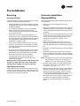
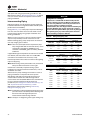
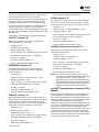
Before starting up units perform the following procedures
to ensure proper unit operation.
To close and reattach the panel, reverse the above
procedures.
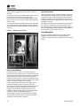
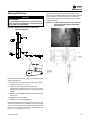
Units with VFD
Note: Verify that all wires are in proper position and not
rubbing once the panel has been secured.
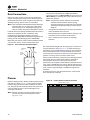
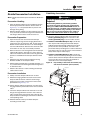
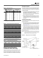
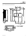
This panel is hinged to allow service access to fan motor
and belt drive components that are located behind it.
Note: The panel weight rating is 225 lbs. total
including factory-installed components.
To swing the panel open:
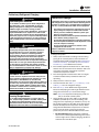
WARNING
Proper Field Wiring and Grounding
Required!
All field wiring MUST be performed by qualified
personnel. Improperly installed and grounded field
wiring poses FIRE and ELECTROCUTION hazards. To
avoid these hazards, you MUST follow requirements for
field wiring installation and grounding as described in
NEC and your local/state electrical codes. Failure to
follow code could result in death or serious injury.
Pre-Start Checklist
Complete this checklist after installing unit to verify all
recommended installation procedures are complete
before start-up.This does not replace the detailed
instructions in the appropriate sections of this manual.
Always read the entire section carefully to become familiar
with the procedures.
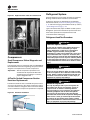
Supply Fan
•
Verify the fan and motor shafts are parallel.
•
Verify the fan and motor sheaves are aligned.
•
Check the fan belt condition and tension. Adjust the
tension if belts are floppy or squeal continually.
Replace worn or fraying belts in matched sets.
•
Ensure the fan rotates freely.
•
Tighten locking screws, bearing set screws and
sheaves.
Disconnect all electric power, including remote
disconnects and discharge all motor start/run
capacitors before servicing. Follow proper lockout/
tagout procedures to ensure the power cannot be
inadvertently energized. For variable frequency drives or
other energy storing components provided by Trane or
others, refer to the appropriate manufacturer’s literature
for allowable waiting periods for discharge of
capacitors. Verify with an appropriate voltmeter that all
capacitors have discharged. Failure to disconnect power
and discharge capacitors before servicing could result in
death or serious injury.
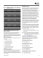
•
Ensure bearing locking collars do not wobble when
rotated.
•
Remove fan assembly tie down bolts. On 20 - 38 ton
units, do not remove the fan assembly tie down bolts
if the fan speed is 750 rpm or less.
•
Ensure fan rotation is in direction of arrow on fan
housing. If incorrect, verify incoming power phasing is
correct. Switch wires on the fan contact to properly
phase fan if necessary.
For additional information regarding the safe discharge
of capacitors, see PROD-SVB06A-EN
•
Ensure trunk ductwork to VAV boxes is complete and
secure to prevent leaks.
•
Verify that all ductwork conforms to NFPA 90A or 90B
and all applicable local codes
WARNING
Hazardous Voltage w/Capacitors!
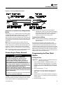
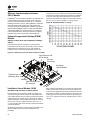
1. Remove the unit center cover panel to the left of the
VFD panel.
2. Verify/remove/discard the sheet metal shipping screws
along the top and bottom edges of the VFD panel.
Ductwork
Water-Cooled Unit Piping
•
3. Disconnect the communications cable from the
keypad on the VFD door panel.
4. Turn the two slotted-head fasteners on the right edge
of the VFD panel fully counterclockwise.
Air-Cooled Units Only
•
Verify leak test was performed after refrigerant piping
was installed.
•
Verify liquid line filter driers installed.
5. Pull on the handle to swing the panel 180°.
Note: To secure the panel in the open position during
service procedures, attach the chain mounted to
the cabinet frame behind the unit center cover
panel to the chain retainer notch on the edge of the
VFD panel.
SCXF-SVX01K-EN
Verify condensate drain, water piping drain plugs,
economizer header, and condenser vent plug are
installed.
Units with Hydronic Heat
•
Verify the entering water temperature sensor is
installed upstream of the hydronic coil.
73