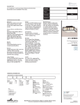
Download Crestron DM-RMC-200-S2 Installation guide
Transcript
Crestron DM-RMC-200-S/S2 DigitalMedia 8G™ Fiber Receiver & Room Controller 200 Operations & Installation Guide This document was prepared and written by the Technical Documentation department at: Important Safety Instructions WARNING: • Read these instructions. • Keep these instructions. • Heed all warnings. • Follow all instructions. • Do not use this apparatus near water. • Clean only with dry cloth. • Do not block any ventilation openings. Install in accordance with the manufacturer's instructions. • Do not install near any heat sources such as radiators, heat registers, stoves, or other apparatus (including amplifiers) that produce heat. • Do not defeat the safety purpose of the polarized or groundingtype plug. A polarized plug has two blades with one wider than the other. A grounding-type plug has two blades and a third grounding prong. The wide blade or the third prong are provided for your safety. If the provided plug does not fit into your outlet, consult an electrician for replacement of the obsolete outlet. TO REDUCE THE RISK OF FIRE OR ELECTRIC SHOCK, DO NOT EXPOSE THIS APPARATUS TO RAIN OR MOISTURE. THE APPARATUS SHALL NOT BE EXPOSED TO DRIPPING OR SPLASHING. OBJECTS FILLED WITH LIQUIDS, SUCH AS VASES, SHOULD NOT BE PLACED ON THE APPARATUS. • Protect the power cord from being walked on or pinched particularly at plugs, convenience receptacles, and the point where they exit from the apparatus. • Only use attachments/accessories specified by the manufacturer. • Use only with the cart, stand, tripod, bracket or table specified by the manufacturer or sold with the apparatus. When a cart is used, use caution when moving the cart/apparatus combination to avoid injury from tip-over. • Unplug this apparatus during lightning storms or when unused for long periods of time. • Refer all servicing to qualified service personnel. Servicing is required when the apparatus has been damaged in any way, such as power-supply cord or plug is damaged, liquid has been spilled or objects have fallen into the apparatus, the apparatus has been exposed to rain or moisture, does not operate normally, or has been dropped. • Disconnect power prior to connecting or disconnecting equipment. • Do not install in direct sunlight. • The apparatus must be installed in a way that the power cord can be removed either from the wall outlet or from the device itself in order to disconnect the mains power. • Prevent foreign objects from entering the device. WARNING: TO PREVENT ELECTRIC SHOCK, DO NOT REMOVE COVER. THERE ARE NO USER SERVICEABLE PARTS INSIDE. ONLY QUALIFIED SERVICE PERSONNEL SHOULD PERFORM SERVICE. CAUTION RISK OF ELECTRIC SHOCK DO NOT OPEN AVIS: RISQUE DE CHOC ELECTRIQUE NE PAS OUVRIR The lightning flash with arrowhead symbol, within an equilateral triangle, is intended to alert the user to the presence of uninsulated “dangerous voltage” within the product's enclosure that may be of sufficient magnitude to constitute a risk of electric shock to persons. The exclamation point within an equilateral triangle is intended to alert the user to the presence of important operating and maintenance (servicing) instructions in the literature accompanying the appliance. IMPORTANT This device can be used with Class 2 output wiring. This device includes an aggregation of separate independent works that are each generally copyrighted by Crestron Electronics, Inc., with all rights reserved. One of those independent works, Linux Bridge Project, is copyrighted under the GNU GENERAL PUBLIC LICENSE, Version2, reproduced in “GNU General Public License” on page 34, where the corresponding source code is available at: ftp://ftp.crestron.com/gpl. The specific patents that cover Crestron products are listed at patents.crestron.com. Crestron, the Crestron logo, CresFiber, Crestron e-Control, Crestron Toolbox, DigitalMedia, DigitalMedia 8G, DM, DM 8G, and Excite are either trademarks or registered trademarks of Crestron Electronics, Inc. in the United States and/or other countries. Dolby and Dolby Digital are either trademarks or registered trademarks of Dolby Laboratories in the United States and/or other countries. DTS and DTS-HD Master Audio are either trademarks or registered trademarks of DTS, Inc. in the United States and/or other countries. HDMI and the HDMI logo are either trademarks or registered trademarks of HDMI Licensing LLC in the United States and/or other countries. Windows is either a trademark or registered trademark of Microsoft Corporation in the United States and/or other countries. Other trademarks, registered trademarks, and trade names may be used in this document to refer to either the entities claiming the marks and names or their products. Crestron disclaims any proprietary interest in the marks and names of others. ©2012 Crestron Electronics, Inc. Regulatory Compliance Compliance Regulatory As of the date of manufacture, the DM-RMC-200-S and DM-RMC-200-S2 have been tested and found to comply with specifications for CE marking and standards per EMC and Radiocommunications Compliance Labelling. Federal Federal Communications Communications Commission Commission (FCC) Compliance Statement This device complies with part 15 of the FCC Rules. Operation is subject to the following conditions: (1) This device may not cause harmful interference and (2) this device must accept any interference received, including interference that may cause undesired operation. CAUTION: Changes or modifications not expressly approved by the manufacturer responsible for compliance could void the user’s authority to operate the equipment. NOTE: This equipment has been tested and found to comply with the limits for a Class A digital device, pursuant to part 15 of the FCC Rules. These limits are designed to provide reasonable protection against harmful interference when the equipment is operated in a commercial environment. This equipment generates, uses, and can radiate radio frequency energy and, if not installed and used in accordance with the instruction manual, may cause harmful interference to radio communications. Operation of this equipment in a residential area is likely to cause harmful interference in which case the user will be required to correct the interference at his own expense. Industry Canada (IC) Compliance Statement CAN-ICES-3 (A)/NMB-3(A) The DM-RMC-200-S and DM-RMC-200-S2 are class 1 laser products. They comply with safety regulations of IEC-60825-1, FDA 21 CFR 1040.11 and FDA 21 CFR 1040.10. WARNING: Visible and invisible laser radiation when open. Avoid direct exposure to beam. NOTE: Plug the included dust cap into the optical transceiver when the fiber optic cable is unplugged. WARNING: These are class A products. In a domestic environment these products may cause radio interference in which case the user may be required to take adequate measures. Crestron DM-RMC-200-S/S2 DigitalMedia 8G Fiber Receiver 200 Contents DigitalMedia 8G Fiber Receiver & Room Controller 200: DM-RMC-200-S/DM-RMC-200-S2 1 Introduction ............................................................................................................................... 1 Features and Functions ................................................................................................ 1 Applications................................................................................................................. 5 Specifications .............................................................................................................. 6 Physical Description.................................................................................................. 10 Setup ........................................................................................................................................ 17 Network Wiring......................................................................................................... 17 Identity Code ............................................................................................................. 17 Supplied Hardware .................................................................................................... 18 Installation ................................................................................................................. 18 Hardware Hookup ..................................................................................................... 21 Programming Software ............................................................................................................ 23 Software Requirements for the PC ............................................................................ 23 Programming with SIMPL Windows ........................................................................ 23 Uploading and Upgrading........................................................................................................ 26 Establishing Communication..................................................................................... 26 Firmware ................................................................................................................... 29 IP Configuration ........................................................................................................ 29 Problem Solving ...................................................................................................................... 30 Troubleshooting......................................................................................................... 30 Reference Documents................................................................................................ 31 Further Inquiries ........................................................................................................ 31 Future Updates .......................................................................................................... 32 Return and Warranty Policies .................................................................................................. 33 Merchandise Returns / Repair Service ...................................................................... 33 Crestron Limited Warranty........................................................................................ 33 GNU General Public License .................................................................................................. 34 Operations & Installation Guide – DOC. 7246B Contents i Crestron DM-RMC-200-S/S2 DigitalMedia 8G Fiber Receiver 200 DigitalMedia 8G Fiber Receiver & Room Controller 200: DM-RMC-200-S/DM-RMC-200-S2 Introduction The DM-RMC-200-S/DM-RMC-200-S2, hereinafter referred to simply as the DM® receiver unless otherwise indicated, provides an advanced one-box interface solution for a single display device as part of a complete Crestron® DigitalMedia™ system. It functions as a DM 8G® (DM-RMC-200-S)/DM 8G SM (DM-RMC-200-S2) fiber receiver, video scaler, audio amplifier, and control interface, providing a single HDMI® output along with speaker and line level audio plus Ethernet, USB HID, and a variety of control ports. Built-in scaling enables the connected display to handle virtually any video signal. A compact, low-profile design allows the DM receiver to be installed discreetly behind a flat panel display or above a ceiling mounted projector. It connects to the head end or source location using one multimode (DM-RMC-200-S) or single-mode (DM-RMC-200-S2) fiber strand.1 Features and Functions DigitalMedia 8G™ multimode (DM-RMC-200-S)/single-mode (DM-RMC-200-S2) fiber receiver, high-definition scaler, audio amplifier, and display controller DM 8G fiber input supports up to 1000 foot (~300 meter) cable length (DM-RMC-200-S)1 DM 8G SM fiber input supports up to 7.5 miles (12 km) cable length (DM-RMC-200-S2)1 Connects to a DM switcher or transmitter (each sold separately) over one multimode (DM-RMC-200-S)/single-mode (DM-RMC-200-S2) fiber strand1 Provides one HDMI or DVI display output2 Accepts any video source from standard NTSC 480i or PAL 576i to HD 1080p60 with Deep Color (Continued on following page) 1. For DM 8G wiring, the maximum DigitalMedia 8G fiber cable length is 1000 feet (~300 meters) using CRESFIBER8G fiber optic cable, or 500 feet (~150 meters) using standard CRESFIBER, CRESFIBER-SINGLE-SC, or generic OM3 simplex multimode fiber optic cable. For DM 8G SMF wiring up to 7.5 miles (12 km) between devices, use Crestron CRESFIBER8G-SM or generic G.652.D (or better) single-mode fiber optic cable. Refer to the latest version of the Crestron DigitalMedia Design Guide (Doc. 4546) for complete system design guidelines. The manual is available from the Crestron Web site at www.crestron.com/dmresources. All wire and cables sold separately. 2. HDMI requires an appropriate adapter or interface cable to accommodate a DVI signal. CBL-HD-DVI interface cable sold separately. Operations & Installation Guide – DOC. 7246B DigitalMedia 8G Fiber Receiver 200: DM-RMC-200-S/S2 1 DigitalMedia 8G Fiber Receiver 200 Crestron DM-RMC-200-S/S2 Features and Functions (Continued) Accepts any computer source from VGA to UXGA/WUXGA Scales the source to match the native resolution of virtually any popular video display or computer monitor Provides intelligent frame rate conversion Allows motion-adaptive de-interlacing or interlacing Allows adjustable overscan or underscan up to 7.5% Provides automatic 3D to 2D signal conversion1 Automatically passes 3D video without scaling to 3D capable displays1 Includes content-adaptive noise reduction 100% HDCP compliant Scalable zoom feature enables 2 x 2, 3 x 2, 3 x 3, 4 x 3, or 4 x 4 video wall capability2 Handles Dolby® TrueHD, DTS-HD Master Audio™, and uncompressed 7.1 linear PCM audio Provides a stereo analog line level audio output Includes a built-in 30 watt stereo amplifier Provides 10BASE-T/100BASE-TX Ethernet and USB HID (Human Interface Device) mouse/keyboard ports Enables device control via CEC, IR, RS-232, and Ethernet Provides two relay control ports and two contact sensing inputs Allows quick, easy setup and diagnostics Low-profile design mounts to a 2-gang US, UK, or European electrical box Includes mounting bracket with integral power pack holder Universal power pack included DigitalMedia 8G Multimode/Single-Mode Fiber DigitalMedia 8G provides a true one-wire transport for moving high-definition video, audio, and Ethernet over fiber optic cable without compression or repeaters. Engineered for ultra high bandwidth and ultimate scalability, DM 8G handles uncompressed video beyond high definition with support for HDCP, Deep Color, and 3D1. Audio capabilities include support for high-bitrate 7.1 audio formats such as Dolby® TrueHD and DTS-HD Master Audio ™ as well as uncompressed linear PCM. All DM-RMC-200-S signals are transported over one strand of multimode fiber, supporting distances up to 1000 feet (~300 meters) using CresFiber® 8G fiber optic cable.3 All DM-RMC-200-S2 signals are transported over one strand of single-mode fiber, supporting distances up to 7.5 miles (12 km) using CresFiber 8G SM or G.652.D single-mode fiber optic cable. 3 1. Automatically passes 3D video if display device supports it (reverts to pass-through mode without scaling). Provides automatic 3D to 2D conversion (with scaling) if display device does not support 3D. 2. Video wall processing requires a separate DM receiver for each individual display. 3. For DM 8G wiring, the maximum DigitalMedia 8G fiber cable length is 1000 feet (~300 meters) using CRESFIBER8G fiber optic cable, or 500 feet (~150 meters) using standard CRESFIBER, CRESFIBER-SINGLE-SC, or generic OM3 simplex multimode fiber optic cable. For DM 8G SMF wiring up to 7.5 miles (12 km) between devices, use Crestron CRESFIBER8G-SM or generic G.652.D (or better) single-mode fiber optic cable. Refer to the latest version of the Crestron DigitalMedia Design Guide (Doc. 4546) for complete system design guidelines. All wire and cables sold separately. 2 DigitalMedia 8G Fiber Receiver 200: DM-RMC-200-S/S2 Operations & Installation Guide – DOC. 7246B Crestron DM-RMC-200-S/S2 DigitalMedia 8G Fiber Receiver 200 Multimedia Display Interface A single HDMI digital AV output port is provided on the DM receiver, supporting HD 1080p60 video and WUXGA computer signals with HDCP, Deep Color, 3D1, and multichannel HD lossless audio—all through one connection. The HDMI output can also handle DVI signals using an appropriate adapter or interface cable.2 Stereo audio outputs are also provided for directly driving a pair of speakers or for connecting to line inputs on the display or a separate amplifier or AV receiver. A single fiber strand connects the DM receiver to a DM switcher or transmitter (each sold separately), transporting video, audio, control, and networking signals through one SC type (DM-RMC-200-S)/LC type (DM-RMC-200-S2) optical connection.3 Multiple DM receivers may be installed to handle each display in a multiroom distribution system, all fed from a central DM switcher (sold separately). Or, a single DM receiver can be fed straight from a DM fiber transmitter (DM 8G transmitter sold separately for the DM-RMC-200-S or DM 8G SM transmitter sold separately for the DM-RMC-200-S2) to extend a computer or AV signal to a single display. High-Definition Scaler Through a distributed scaler approach, DigitalMedia technology delivers a flexible and user-friendly solution for routing multiple disparate sources to many different display devices. By placing an independent high-performance scaler at every display device, DM ensures an optimal image on every screen regardless of the sources that are selected. Distributed scaling allows a high-resolution computer source to be viewed on any display in the building. It also allows a high-definition 3D source to be viewed on lower resolution 2D displays without compromising the original signal. The DM receiver accepts any video source from standard NTSC 480i to HD 1080p60 with Deep Color, as well as computer sources from VGA to UXGA/WUXGA, and scales them perfectly to match the native resolution of the video display. A range of common output resolutions is supported to work with virtually any popular flat panel display, projector, or computer monitor. Intelligent frame rate conversion enables support for 24p and PAL format sources, and 3D to 2D conversion allows 3D content to be fed simultaneously to separate 3D and 2D displays. Setup and use of the scaler is simplified through fully automatic operation utilizing the display’s EDID.1, 4 A pair of DM receivers can also be used to facilitate a dual-projector 3D setup, steering the left eye portion of a 3D signal to one projector and the right eye portion to the other. This is done using the scaler’s 3D to 2D conversion mode, enabling 3D capability with scaling. 1. Automatically passes 3D video if display device supports it (reverts to pass-through mode without scaling). Provides automatic 3D to 2D conversion (with scaling) if display device does not support 3D. 2. HDMI requires an appropriate adapter or interface cable to accommodate a DVI signal. CBL-HD-DVI interface cable sold separately. 3. For DM 8G wiring, the maximum DigitalMedia 8G fiber cable length is 1000 feet (~300 meters) using CRESFIBER8G fiber optic cable, or 500 feet (~150 meters) using standard CRESFIBER, CRESFIBER-SINGLE-SC, or generic OM3 simplex multimode fiber optic cable. For DM 8G SMF wiring up to 7.5 miles (12 km) between devices, use Crestron CRESFIBER8G-SM or generic G.652.D (or better) single-mode fiber optic cable. Refer to the latest version of the Crestron DigitalMedia Design Guide (Doc. 4546) for complete system design guidelines. All wire and cables sold separately. 4. EDID (Extended Display Identification Data) is data embedded in an HDMI, DVI, or VGA signal that enables a display device to tell the source device what resolutions and formats it can support, allowing the source to configure itself automatically to feed the best signal that both devices can support. Operations & Installation Guide – DOC. 7246B DigitalMedia 8G Fiber Receiver 200: DM-RMC-200-S/S2 3 DigitalMedia 8G Fiber Receiver 200 Crestron DM-RMC-200-S/S2 Video Wall Processing The DM receiver provides zoom capability on its output to display just a portion of the source image. Using this feature, multiple units may be combined to configure a high-definition video wall composed of up to 16 individual displays. Configurations of 2 x 2, 3 x 2, 3 x 3, 4 x 3, or 4 x 4 are supported, and all that is required is a separate DM receiver for each display and a DM switcher (sold separately) with sufficient DM 8G/DM 8G SM fiber outputs. Audio Amplifier The DM receiver is equipped with stereo analog audio outputs and a built-in 30 watt stereo amplifier. The output volume is adjustable via a control system using a keypad, touch screen, or handheld remote. The amplifier provides plenty of power to drive a pair of local speakers, or the line output can be used to connect directly to the display device, a pair of amplified speakers, or a local sound system. LAN Connectivity Along with high-definition AV and control, DigitalMedia technology also integrates high-speed Ethernet networking for a total signal distribution solution. The DM receiver includes a 10BASE-T/100BASE-TX Ethernet port, providing a convenient LAN connection for a local network device. Keyboard/Mouse Extender The DM receiver also functions as a keyboard/mouse extender, allowing a USB HID-compliant keyboard and/or mouse to be connected at the display location and used to control a computer or other component located at the central equipment rack or some other location. Embedded Device Control The DM receiver includes built-in RS-232, IR, and Ethernet control ports to allow programmable control of the display device connected to it. It can also provide an alternative to such conventional control methods by harnessing the CEC (Consumer Electronics Control) signal embedded in HDMI. Through its connection to the control system, the DM receiver provides a gateway for controlling the display device through the HDMI connection, potentially eliminating the need for any dedicated control wires or IR emitters. Two low-voltage relay ports are also included on the DM receiver for control of a projection screen or lift. In addition, there are two discrete digital input ports to accommodate room occupancy sensors, power sensors, or contact closures for enhanced automation and monitoring. Low-Profile Installation Its low-profile design makes the DM receiver perfect for installation behind a flat panel display or above a ceiling mounted projector. It mounts to a standard 2-gang US, UK, or European electrical box using the mounting bracket provided. The bracket includes a convenient holder for the external power pack, providing for a clean installation that protrudes only 1.6 inches (~41 mm) from the mounting surface. Connections are positioned on the top, bottom, and rear of the unit. The design of the mounting bracket allows wires up to 0.23 inches (~6 mm) in diameter to extend from the electrical box as needed. An array of indicators is provided on the front of the DM receiver for easy setup and troubleshooting. 4 DigitalMedia 8G Fiber Receiver 200: DM-RMC-200-S/S2 Operations & Installation Guide – DOC. 7246B Crestron DM-RMC-200-S/S2 DigitalMedia 8G Fiber Receiver 200 Applications The diagram below shows a DM-RMC-200-S in a standalone application. In this type of application, the DM-RMC-200-S is used with a DM 8G fiber transmitter such as the DM-TX-201-S (sold separately) and is not used with a DM switcher. DM-RMC-200-S in a Standalone Application In a DM-RMC-200-S2 standalone application, the DM-RMC-200-S2 is used with a DM 8G SM fiber transmitter such as the DM-TX-201-S2 (sold separately) and is not used with a DM switcher. Operations & Installation Guide – DOC. 7246B DigitalMedia 8G Fiber Receiver 200: DM-RMC-200-S/S2 5 DigitalMedia 8G Fiber Receiver 200 Crestron DM-RMC-200-S/S2 Specifications Specifications for the DM receiver are listed in the following table. DM-RMC-200-S/DM-RMC-200-S2 Specifications SPECIFICATION DETAILS Video Scaler1 HD video scaler, motion-adaptive deinterlacer, interlacer, intelligent frame rate conversion, Deep Color support, 2 3D to 2D conversion , content-adaptive noise reduction, widescreen format selection (zoom, stretch, maintain aspect ratio, or 1:1), video wall processing (2 x 2, 3 x 2, 3 x 3, 4 x 3, or 4 x 4)3 Input Signal Type DM-RMC-200-S: DM 8G fiber (DigitalMedia over one multimode fiber optic strand)4 DM-RMC-200-S2: DM 8G SMF (DigitalMedia over one single-mode fiber optic strand)4 HDMI, DVI5 Output Signal Types Formats HDMI with Deep Color & 3D2, DVI, HDCP content protection support Input Resolutions Progressive 640 x 480 @ 60 Hz 720 x 480 @ 60 Hz (480p) 720 x 576 @ 50 Hz (576p) 800 x 600 @ 60 Hz 848 x 480 @ 60 Hz 852 x 480 @ 60 Hz 854 x 480 @ 60 Hz 1024 x 768 @ 60 Hz 1024 x 852 @ 60 Hz 1024 x 1024 @ 60 Hz 1280 x 720 @ 50 Hz (720p50) 1280 x 720 @ 60 Hz (720p60) 1280 x 768 @ 60 Hz 1280 x 800 @ 60 Hz 1280 x 960 @ 60 Hz 1280 x 1024 @ 60 Hz 1360 x 768 @ 60 Hz 1365 x 1024 @ 60 Hz 1366 x 768 @ 60 Hz 1400 x 1050 @ 60 Hz 1440 x 900 @ 60 Hz 1600 x 900 @ 60 Hz 1600 x 1200 @ 60 Hz 1680 x 1050 @ 60 Hz 1920 x 1080 @ 24 Hz (1080p24) 1920 x 1080 @ 25 Hz (1080p25) 1920 x 1080 @ 50 Hz (1080p50) 1920 x 1080 @ 60 Hz (1080p60) 1920 x 1200 @ 60 Hz plus any other resolution allowed by HDMI up to 165 MHz pixel clock (Continued on following page) 6 DigitalMedia 8G Fiber Receiver 200: DM-RMC-200-S/S2 Operations & Installation Guide – DOC. 7246B Crestron DM-RMC-200-S/S2 DigitalMedia 8G Fiber Receiver 200 DM-RMC-200-S/DM-RMC-200-S2 Specifications (Continued) SPECIFICATION DETAILS Video Input Resolutions (Continued) 720 x 480 @ 30 Hz (480i) 720 x 576 @ 25 Hz (576i) 1920 x 1080 @ 25 Hz (1080i25) 1920 x 1080 @ 30 Hz (1080i30) plus any other resolution allowed by HDMI up to 165 MHz pixel clock Interlaced Scaler Output Resolutions Progressive 640 x 480 @ 60 Hz 720 x 480 @ 60 Hz (480p) 720 x 576 @ 50 Hz (576p) 800 x 600 @ 60 Hz 848 x 480 @ 60 Hz 1024 x 768 @ 60 Hz6 1280 x 720 @ 50 Hz (720p50) 1280 x 720 @ 60 Hz (720p60) 1280 x 768 @ 60 Hz 1280 x 800 @ 60 Hz6 1280 x 960 @ 60 Hz 1280 x 1024 @ 60Hz 1360 x 768 @ 60 Hz 1366 x 768 @ 60 Hz6 1400 x 1050 @ 60 Hz6 1440 x 900 @ 60 Hz6 1600 x 900 @ 60 Hz7 1600 x 1200 @ 60 Hz 1680 x 1050 @ 60 Hz6 1920 x 1080 @ 50 Hz (1080p50) 1920 x 1080 @ 60 Hz (1080p60) 7 1920 x 1200 @ 60 Hz 2048 x 1152 @ 60 Hz7 Interlaced 720 x 480 @ 30 Hz (480i) 720 x 576 @ 25 Hz (576i) 1920 x 1080 @ 25 Hz (1080i25) 1920 x 1080 @ 30 Hz (1080i30) Pass-Thru Output Resolutions Matched to input Audio Input Signal Type DM-RMC-200-S: DM 8G fiber DM-RMC-200-S2: DM 8G SMF Output Signal Types HDMI, analog stereo (speaker and line level) Formats HDMI Dolby Digital®, Dolby Digital EX, Dolby Digital Plus, Dolby® TrueHD, DTS®, DTS-ES, DTS 96/24, DTS-HD High Res, DTS-HD Master Audio™, up to 8ch PCM Analog Stereo 2-Channel Digital-to-Analog Conversion 24-bit 48 kHz (Continued on following page) Operations & Installation Guide – DOC. 7246B DigitalMedia 8G Fiber Receiver 200: DM-RMC-200-S/S2 7 DigitalMedia 8G Fiber Receiver 200 Crestron DM-RMC-200-S/S2 DM-RMC-200-S/DM-RMC-200-S2 Specifications (Continued) SPECIFICATION Audio (Continued) Performance (Analog) Amplifier Output Power8 Frequency Response S/N Ratio THD+N Stereo Separation Volume Gain Range (Analog) Communications DigitalMedia Ethernet USB Power Requirements Power Pack Minimum 2-Series Control System Update File9, 10 Environmental Temperature Humidity Heat Dissipation Enclosure Chassis Mounting Dimensions Height Width Depth Weight Included Accessory DETAILS 15 watts per channel at 8 ohms 20 Hz to 20 kHz ±0.5 dB (line), 20 Hz to 16 kHz ±3 dB (speaker) >95 dB (line), >75 dB (speaker) 20 Hz to 20 kHz A-weighted <0.005% @ 1 kHz (line), <0.3% @ 1 kHz (speaker) >90 dB (line), >60 dB (speaker) -80 dB to 0 dB DM 8G fiber (DM-RMC-200-S)/ DM 8G SMF (DM-RMC-200-S2), HDCP management, EDID format management, CEC 10BASE-T/100BASE-TX, auto-switching, auto-negotiating, auto-discovery, full/half duplex, DHCP Supports USB HID class devices 2 A @ 24 volts dc; 100-240 volts ac, 50/60 Hz power pack included Version 4.003.0029 or later 32º to 104º F (0º to 40º C) 10% to 90% RH (non-condensing) Power amp off, no relay or USB loads: 60 Btu/h; Power amp on, with relay and USB loads: 80 Btu/h (maximum) Metal, black finish, vented sides and front Mounts to a 2-gang electrical box, 2-gang UK (BS 4662) electrical box, or 2-gang European (DIN 49073) electrical box; Bracket includes holder for the included power pack 7.92 in (201 mm) 10.83 in (275 mm) with mounting bracket 1.73 in (44 mm) with mounting bracket 3.3 lb (1.5 kg) including bracket and power pack Universal 24 Volt DC Power Pack (Continued on following page) 8 DigitalMedia 8G Fiber Receiver 200: DM-RMC-200-S/S2 Operations & Installation Guide – DOC. 7246B Crestron DM-RMC-200-S/S2 DigitalMedia 8G Fiber Receiver 200 DM-RMC-200-S/DM-RMC-200-S2 Specifications (Continued) SPECIFICATION DETAILS Available Accessories CBL Series Crestron Certified Interface Cables CNSP-XX Custom Serial Interface Cable CRESFIBER-CONNSC50UM-12 (DM-RMC-200-S only) CresFiber Fiber Optic Cable Connector CRESFIBER-SINGLE-SC (DM-RMC-200-S only) CresFiber Simplex Fiber Optic Cable Assembly, 50/125, SC CRESFIBER-SINGLESC-ARMORED (DM-RMC-200-S only) CresFiber ARMORED Simplex Fiber Optic Cable Assembly, 50/125, SC CRESFIBER-SINGLESC-CLEAR (DM-RMC-200-S only) CresFiber CLEAR Simplex Fiber Optic Cable Assembly, 50/125, SC CRESFIBER-SM-CONNLC-12 (DM-RMC-200-S2 only) CresFiber Single-Mode Fiber Optic Cable Connector CRESFIBER-TK CresFiber Termination Kit CRESFIBER8G (DM-RMC-200-S only) CresFiber 8G Fiber Optic Cable CRESFIBER8G-SM (DM-RMC-200-S2 only) CresFiber 8G Single-Mode Fiber Optic Cable IRP2 IR Emitter Probe MP-WP Series Media Presentation Wall Plates MPI-WP Series Media Presentation Wall Plates – International Version 1. Using the DMTool in Crestron Toolbox™, the scaler can be enabled/disabled. 2. Automatically passes 3D video if display device supports it (reverts to pass-through mode without scaling). Provides automatic 3D to 2D conversion (with scaling) if display device does not support 3D. 3. Video wall processing requires a separate DM receiver for each individual display. 4. For DM 8G wiring, the maximum DigitalMedia 8G fiber cable length is 1000 feet (~300 meters) using CRESFIBER8G fiber optic cable, or 500 feet (~150 meters) using standard CRESFIBER, CRESFIBER-SINGLE-SC, or generic OM3 simplex multimode fiber optic cable. For DM 8G SMF wiring up to 7.5 miles (12 km) between devices, use Crestron CRESFIBER8G-SM or generic G.652.D (or better) single-mode fiber optic cable. Refer to the latest version of the Crestron DigitalMedia Design Guide (Doc. 4546) for complete system design guidelines. All wire and cables sold separately. 5. HDMI requires an appropriate adapter or interface cable to accommodate a DVI signal. CBL-HD-DVI interface cable sold separately. 6. With or without reduced blanking. 7. With reduced blanking only. 8. Using the DMTool in Crestron Toolbox, the amplifier can be enabled/disabled. 9. The latest software versions can be obtained from the Crestron Web site. Refer to the NOTE following these footnotes. 10. Crestron 2-Series control systems include the AV2 and PRO2. Consult the latest Crestron Product Catalog for a complete list of 2-Series control systems. NOTE: Crestron software and any files on the Web site are for authorized Crestron dealers and Crestron Authorized Independent Programmers (CAIPs) only. New users may be required to register to obtain access to certain areas of the site (including the FTP site). Operations & Installation Guide – DOC. 7246B DigitalMedia 8G Fiber Receiver 200: DM-RMC-200-S/S2 9 DigitalMedia 8G Fiber Receiver 200 Crestron DM-RMC-200-S/S2 Physical Description This section provides information on the connections, controls and indicators available on the DM receiver. DM-RMC-200-S/DM-RMC-200-S2 Physical View (Front Panel) DM-RMC-200-S DM-RMC-200-S2 10 DigitalMedia 8G Fiber Receiver 200: DM-RMC-200-S/S2 Operations & Installation Guide – DOC. 7246B Crestron DM-RMC-200-S/S2 DigitalMedia 8G Fiber Receiver 200 DM-RMC-200-S/DM-RMC-200-S2 Physical View (Rear Panel) DM-RMC-200-S/DM-RMC-200-S2 Physical View (Top Panel) DM-RMC-200-S DM-RMC-200-S2 DM-RMC-200-S/DM-RMC-200-S2 Physical View (Bottom Panel) Operations & Installation Guide – DOC. 7246B DigitalMedia 8G Fiber Receiver 200: DM-RMC-200-S/S2 11 DigitalMedia 8G Fiber Receiver 200 Crestron DM-RMC-200-S/S2 DM-RMC-200-S/DM-RMC-200-S2 Overall Dimensions (Front and Side Panels without Mounting Bracket Installed) 7.60 in (193 mm) 7.45 in (190 mm) 7.92 in (201 mm) 7.54 in (192 mm) 1.05 in ( 27 mm) 1.46 in (37 mm) DM-RMC-200-S/DM-RMC-200-S2 Overall Dimensions (Front and Side Panels with Mounting Bracket Installed) 10.83 in (275 mm ) 1.30 in (33 mm) 4.93 in (126 mm) 3.30 in (84 mm) 1.23 in (32 mm) 1.53 in (39 mm) 1.62 in (41 mm) 1.73 in (44 mm) 12 DigitalMedia 8G Fiber Receiver 200: DM-RMC-200-S/S2 Operations & Installation Guide – DOC. 7246B Crestron DM-RMC-200-S/S2 DigitalMedia 8G Fiber Receiver 200 DM-RMC-200-S/DM-RMC-200-S2 Connectors, Controls & Indicators (Front Panel) 1 2 3 4 5 6 DM-RMC-200-S/DM-RMC-200-S2 Connectors, Controls & Indicators (Top Panel) DM-RMC-200-S 7 9 8 11 12 11 12 10 DM-RMC-200-S2 7 13 8 10 DM-RMC-200-S/DM-RMC-200-S2 Connectors, Controls & Indicators (Bottom Panel) 14 Operations & Installation Guide – DOC. 7246B 15 16 17 18 DigitalMedia 8G Fiber Receiver 200: DM-RMC-200-S/S2 13 DigitalMedia 8G Fiber Receiver 200 Crestron DM-RMC-200-S/S2 DM-RMC-200-S/DM-RMC-200-S2 Connectors, Controls & Indicators (Rear Panel) 19 20 21 22 Connectors, Controls & Indicators # CONNECTORS1, CONTROLS & INDICATORS 1 PWR LED 2 DM LINK LED 3 VIDEO LED 4 USB HID LED (1) Green LED, indicates a valid device connection and activity on the USB HID port 5 SETUP (LED and Button) (1) Red LED and (1) miniature recessed push button for Ethernet setup 6 RESET (1) Miniature recessed push button for hardware reset 7 AUDIO OUT R, L (Speaker)2 (2) 2-pin 5 mm detachable terminal blocks; Left and right speaker level audio outputs; Paralleled with rear panel AUDIO OUT connectors; Wire Size: Connector accepts 12 AWG maximum; Output Power: 15 watts per channel at 8 ohms DESCRIPTION (1) Green LED, indicates operating power supplied from local power pack (1) Green LED, indicates DM link status (1) Green LED, indicates video signal presence and lock status (Continued on following page) 14 DigitalMedia 8G Fiber Receiver 200: DM-RMC-200-S/S2 Operations & Installation Guide – DOC. 7246B Crestron DM-RMC-200-S/S2 DigitalMedia 8G Fiber Receiver 200 Connectors, Controls & Indicators (Continued) # CONNECTORS1, CONTROLS & INDICATORS 8 AUDIO OUT R, L (Line) 9 DM IN MMF/SC (DM-RMC-200-S only) (1) SC female optical fiber connector; DM 8G fiber input; Connects to DM 8G fiber output of a DM switcher, transmitter, or other DM device via CresFiber 8G multimode fiber optic cable3 10 DM IN LED (1) Green LED, indicates DM link status 11 LAN Pin 1 Amber LED Pin 8 Green LED DESCRIPTION (2) RCA female; Stereo unbalanced line level audio output; Output Level: 2 Vrms maximum Output Impedance: 100 ohms nominal (1) 8-pin RJ-45 female, shielded, with two LED indicators; 10BASE-T/100BASE-TX Ethernet port; Green LED indicates Ethernet link status; Amber LED indicates Ethernet activity PIN SIGNAL PIN SIGNAL 1 2 3 4 TX + TX RX + N/C 5 6 7 8 N/C RX N/C N/C 12 24 V 2.0A MAX 13 DM IN SMF/LC (DM-RMC-200-S2 only) (1) LC female optical fiber connector; DM 8G single-mode fiber input; Connects to DM 8G SMF output of a DM switcher, transmitter, or other DM device via CresFiber 8G SM single-mode fiber 3 optic cable 14 DIG IN (1) 2-pin 3.5 mm detachable terminal block; Digital/contact closure sensing input; Rated for 0-24 volts dc, referenced to GND; Input Impedance: 2.2k ohms pulled up to 5 volts dc; Logic Threshold: 2.5 volts dc nominal with 1 volt hysteresis band SG 15 HDMI OUT 16 USB HID (1) 2.1 x 5.5 mm dc power connector; 24 volt dc power input; Power pack included (1) 19-pin Type A HDMI female; HDMI digital video/audio output; Also supports DVI4 (1) USB Type A female; USB 2.0 host port for connection of a mouse/keyboard or other USB HID-compliant device (Continued on following page) Operations & Installation Guide – DOC. 7246B DigitalMedia 8G Fiber Receiver 200: DM-RMC-200-S/S2 15 DigitalMedia 8G Fiber Receiver 200 Crestron DM-RMC-200-S/S2 Connectors, Controls & Indicators (Continued) # CONNECTORS1, CONTROLS & INDICATORS 17 COM (1) 5-pin 3.5 mm detachable terminal block, bidirectional RS-232 port; Up to 115.2k baud, hardware and software handshaking support 18 IR 1-2 (1) 4-pin 3.5 mm detachable terminal block comprising two IR/Serial ports; IR output up to 1.1 MHz; 1-way serial TTL/RS-232 (0-5 volts) up to 19200 baud5 19 G 20 AUDIO OUT L, R (Speaker) 2 21 DIG IN SG 22 RELAY 1-2 DESCRIPTION (1) 06-32 screw, chassis ground lug (2) 2-pin 5 mm detachable terminal blocks; Left and right speaker level audio outputs; Paralleled with top panel AUDIO OUT (Speaker) connectors; Wire Size: Connector accepts 12 AWG maximum; Output Power: 15 watts per channel at 8 ohms (1) 2-pin 3.5 mm detachable terminal block; Digital/contact closure sensing input; Rated for 0-24 volts dc, referenced to GND; Input Impedance: 2.2k ohms pulled up to 5 volts dc; Logic Threshold: 2.5 volts dc nominal with 1 volt hysteresis band (1) 4-pin 3.5 mm detachable terminal block comprising two normally open, isolated relays; Rated 1 amp, 30 volts ac/dc; MOV arc suppression across contacts 1. Interface connectors for the AUDIO OUT (Speaker), DIG IN, COM, IR, and RELAY ports are provided with the unit. 2. The set of speaker level audio outputs on the top panel and the set of speaker level audio outputs on the rear panel cannot be used simultaneously. Either set of speaker level audio outputs should be used at one time. 3. For DM 8G wiring, the maximum DigitalMedia 8G fiber cable length is 1000 feet (~300 meters) using CRESFIBER8G fiber optic cable, or 500 feet (~150 meters) using standard CRESFIBER, CRESFIBER-SINGLE-SC, or generic OM3 simplex multimode fiber optic cable. For DM 8G SMF wiring up to 7.5 miles (12 km) between devices, use Crestron CRESFIBER8G-SM or generic G.652.D (or better) single-mode fiber optic cable. Refer to the latest version of the Crestron DigitalMedia Design Guide (Doc. 4546) for complete system design guidelines. All wire and cables sold separately. 4. HDMI requires an appropriate adapter or interface cable to accommodate a DVI signal. CBL-HD-DVI interface cable sold separately. 5. Maximum string length for serial commands sent via the IR port should be no greater than 40 characters. 16 DigitalMedia 8G Fiber Receiver 200: DM-RMC-200-S/S2 Operations & Installation Guide – DOC. 7246B Crestron DM-RMC-200-S/S2 DigitalMedia 8G Fiber Receiver 200 Setup Network Wiring When wiring the DM network, consider the following: Use Crestron Certified Wire. Use Crestron power supplies for Crestron equipment. CAUTION: Failure to use Crestron power supplies could cause equipment damage or void the Crestron warranty. Provide sufficient power to the system. For DigitalMedia 8G multimode fiber wiring, CresFiber 8G is recommended. Refer to the following table for the maximum transmission distance of CresFiber 8G and other fiber optic cable. DigitalMedia 8G Multimode Fiber Wiring and Maximum Transmission Distance CABLE TYPE CresFiber 8G MAXIMUM TRANSMISSION DISTANCE 1000 feet (~300 meters) CresFiber 500 feet (~150 meters) Generic OM3 500 feet (~150 meters) For DigitalMedia 8G single-mode fiber wiring, CresFiber 8G SM is recommended. The maximum transmission distance of CresFiber 8G SM or generic G.652.D (or better) single-mode fiber optic cable is 7.5 miles (12 km). Refer to the latest version of the Crestron DigitalMedia Design Guide (Doc. 4546) for complete system design guidelines. The DM receiver also uses high-speed Ethernet for communications between the device and a control system, computer, media server, and other IP-based devices. For general information on connecting Ethernet devices in a Crestron system, refer to the latest version of the Crestron e-Control Reference Guide (Doc. 6052), which is available from the Crestron Web site (www.crestron.com/manuals). For information specifically related to Ethernet connectivity using DigitalMedia devices, refer to the latest version of the Crestron IP Considerations Guide for the IT Professional (Doc. 4579), which is also available from the Crestron Web site (www.crestron.com/dmresources). Identity Code NOTE: In the SIMPL Windows program, the IP ID of the DM receiver is assigned automatically and does not require additional programming when the DM receiver is dropped onto an output card of a DM switcher. Use the information below when the DM receiver is dropped directly into an Ethernet slot on the control system in SIMPL Windows without a DM switcher. The IP ID is set within the IP table of the DM receiver using Crestron Toolbox™. For information on setting an IP table, refer to the Crestron Toolbox help file. The IP IDs of multiple DM receivers in the same system must be unique. Operations & Installation Guide – DOC. 7246B DigitalMedia 8G Fiber Receiver 200: DM-RMC-200-S/S2 17 DigitalMedia 8G Fiber Receiver 200 Crestron DM-RMC-200-S/S2 When setting the IP ID, consider the following: The IP ID of each unit must match an IP ID specified in the SIMPL Windows program. Each device using IP to communicate with a control system must have a unique IP ID. Supplied Hardware The hardware supplied with the DM receiver is listed in the following table. Supplied Hardware for the DM-RMC-200-S/DM-RMC-200-S2 DESCRIPTION PART NUMBER QUANTITY Mounting Bracket 2032478 1 Screws, 06-32 x 1/4”, Pan, Phil 2007215 4 Screws, 06-32 x 1”, Pan, Phil 2007250 2 Screws, 06-32 x 3/4”, Slot 2009211 4 Standoffs, 06-32 x 1-1/4” 2007056 4 Tie Wraps 2013608 2 Installation Ventilation The DM receiver should be used in a well-ventilated area. The venting holes should not be obstructed under any circumstances. To prevent overheating, do not operate this product in an area that exceeds the environmental temperature range listed in the table of specifications. Mounting The DM receiver mounts to a 2-gang electrical box (not included). To mount the DM receiver, perform the following steps (refer to the illustration on the following page): 1. Attach the four included 06-32 x 1-1/4” standoffs (2007056) to the studs of the included mounting bracket (2032478). 2. Using the four included 06-32 x 3/4” slot head screws (2009211), attach the included mounting bracket (2032478) to the electrical box. 3. Ground the DM receiver and attach the proper cables to the rear of the unit (refer to “Hardware Hookup” which starts on page 21 for information). 4. Using the four included 06-32 x 1/4” Phillips head screws (2007215), attach the DM receiver to the standoffs (2007056). CAUTION: Excess wire that is pinched between the DM receiver and the electrical box can short out. Ensure that all excess wire is completely inside the electrical box and is not between the box and the DM receiver. 18 DigitalMedia 8G Fiber Receiver 200: DM-RMC-200-S/S2 Operations & Installation Guide – DOC. 7246B Crestron DM-RMC-200-S/S2 DigitalMedia 8G Fiber Receiver 200 Mounting the DM-RMC-200-S/DM-RMC-200-S2 Standoffs (4) #06-32 x 1-1/4” (2007056) Screws (4) #06-32 x 3/4” (2009211) 2-Gang Electrical Box (Not Included) Mounting Bracket (2032478) Screws (4) #06-32 x 1/4” (2007215) Installing the Power Pack The included mounting bracket (2032478), which is used to attach the DM receiver to an electrical box (not included), provides a holder for the included power pack (2022484). To install the power pack, perform the following steps (refer to the illustration on the following page): 1. Slide the power pack (2022484) into the holder. 2. Using the two included 06-32 x 1” Phillips head screws (2007250), thread the screws through the two holes on the front of the power pack holder to hold the power pack in place. 3. Using the two included tie wraps (2013608), thread a tie wrap through the hole on the top and bottom of the holder, and then fasten the tie wraps to the power pack cable. Operations & Installation Guide – DOC. 7246B DigitalMedia 8G Fiber Receiver 200: DM-RMC-200-S/S2 19 DigitalMedia 8G Fiber Receiver 200 Crestron DM-RMC-200-S/S2 Installing the Power Pack Power Pack Holder Tie-Wrap Holes (2) Screws (2) #06-32 x 1” (2007250) Power Pack (2022484) Installation of the power pack in the holder is shown below. Power Pack Installed in Holder of Mounting Bracket 20 DigitalMedia 8G Fiber Receiver 200: DM-RMC-200-S/S2 Operations & Installation Guide – DOC. 7246B Crestron DM-RMC-200-S/S2 DigitalMedia 8G Fiber Receiver 200 Hardware Hookup Make the necessary connections as called out in the following illustrations. Refer to “Network Wiring” on page 17. Apply power after all connections have been made. Hardware Connections for the DM-RMC-200-S (Top Panel) AUDIO OUT R, L (SPEAKER): Amplified Stereo Audio Output AUDIO OUT R, L (LINE): Stereo Unbalanced Line Level Audio Output LAN: 10BASE-T/ 100BASE-TX Ethernet to Local Network Device 24 V 2.0A MAX: From Power Pack (Included) DM IN MMF/SC: From DM Switcher, Transmitter, or Other DM Device Hardware Connections for the DM-RMC-200-S2 (Top Panel) AUDIO OUT R, L (SPEAKER): Amplified Stereo Audio Output AUDIO OUT R, L (LINE): Stereo Unbalanced Line Level Audio Output LAN: 10BASE-T/ 100BASE-TX Ethernet to Local Network Device 24 V 2.0A MAX: From Power Pack (Included) DM IN SMF/LC: From DM Switcher, Transmitter, or Other DM Device Operations & Installation Guide – DOC. 7246B DigitalMedia 8G Fiber Receiver 200: DM-RMC-200-S/S2 21 DigitalMedia 8G Fiber Receiver 200 Crestron DM-RMC-200-S/S2 Hardware Connections for the DM-RMC-200-S/DM-RMC-200-S2 (Bottom Panel) HDMI OUT: Digital Video/ Audio Output USB HID: From USB HID-Compliant Device DIG IN: Software Programmable Digital Input COM: To RS-232 Device IR: To IR Controllable Device Hardware Connections for the DM-RMC-200-S/DM-RMC-200-S2 (Rear Panel) AUDIO OUT L, R (SPEAKER): Amplified Stereo Audio Output Ground RELAY 1-2: To Controllable Devices DIG IN: Software Programmable Digital Input NOTE: Ensure that the unit is properly grounded by connecting the chassis ground lug to an earth ground (building steel). NOTE: Do not connect the set of speaker level audio outputs on the top panel and the set of speaker level audio outputs on the rear panel simultaneously. Only one set of speaker level audio outputs can be used at one time. NOTE: For optimum performance, Crestron recommends using CresFiber 8G fiber optic cable for the DM-RMC-200-S and CresFiber 8G SM fiber optic cable for the DM-RMC-200-S2. NOTE: Fiber optic cable connectors and cable ends should be protected from contamination and scratching at all times. When cable is not connected, protect the optical receiver on the DM receiver by using the included cap. Fiber ends should be handled carefully and the cable should not be bent or coiled tightly. 22 DigitalMedia 8G Fiber Receiver 200: DM-RMC-200-S/S2 Operations & Installation Guide – DOC. 7246B Crestron DM-RMC-200-S/S2 DigitalMedia 8G Fiber Receiver 200 Programming Software Have a question or comment about Crestron software? Answers to frequently asked questions (FAQs) can be viewed in the Online Help section of the Crestron Web site. To post a question or to view questions submitted to Crestron’s True Blue Support, log in at www.crestron.com/onlinehelp. First-time users must establish a user account to fully benefit from all available features. Software Requirements for the PC NOTE: The latest software can be downloaded from the Crestron Web site (www.crestron.com/software). Crestron provides an assortment of Windows-based software tools to develop a customized system. Use Crestron SIMPL Windows to create a program to control the DM receiver. Programming with SIMPL Windows SIMPL Windows is Crestron’s premier software for programming Crestron control systems. It is organized into two separate but equally important “Managers”: Configuration and Program. Configuration Manager Configuration Manager is the view where programmers “build” a Crestron control system by selecting hardware from the Device Library. 1. To incorporate the DM receiver into the system, drag the DM receiver from the DigitalMedia | DM Receivers folder of the Device Library and drop it into either of the following in System Views: A compatible output card of a DM switcher Directly to a card in the Ethernet slot of the control system (used without a DM switcher) Locating the DM-RMC-200-S/DM-RMC-200-S2 in the Device Library Operations & Installation Guide – DOC. 7246B DigitalMedia 8G Fiber Receiver 200: DM-RMC-200-S/S2 23 DigitalMedia 8G Fiber Receiver 200 Crestron DM-RMC-200-S/S2 The system tree of the control system displays the DM receiver in the appropriate slot with a default IP ID as shown in the following illustrations. In the first example, the DM-RMC-200-S is used with the DMCO-40 output card in a DM-MD8X8 switcher. In the second example, the DM-RMC-200-S is used with the C2ENET-2 card in an Ethernet slot on the control system. C2ENET-2 Device, Slot 8 (Using Output Card in a DM Switcher) C2ENET-2 Device, Slot 8 (Using Ethernet Slot on Control System) 2. If additional DM receivers are to be added, repeat step 1 for each device. Each DM receiver is assigned a different IP ID. 3. If necessary, double-click a device to open the “Device Settings” window and change the IP ID as shown in the following illustration. “Device Settings: Crestron DM-RMC-200-S” Window 24 DigitalMedia 8G Fiber Receiver 200: DM-RMC-200-S/S2 Operations & Installation Guide – DOC. 7246B Crestron DM-RMC-200-S/S2 DigitalMedia 8G Fiber Receiver 200 NOTE: The ID code specified in the SIMPL Windows program must match the IP ID of each unit. Refer to “Identity Code,” which starts on page 17. Program Manager Program Manager is the view where programmers “program” a Crestron control system by assigning signals to symbols. The symbol can be viewed by double-clicking the icon or dragging it into Detail View. Each signal in the symbol is described in the SIMPL Windows help file (F1). Operations & Installation Guide – DOC. 7246B DigitalMedia 8G Fiber Receiver 200: DM-RMC-200-S/S2 25 DigitalMedia 8G Fiber Receiver 200 Crestron DM-RMC-200-S/S2 Uploading and Upgrading Crestron recommends using the latest programming software and that each device contains the latest firmware to take advantage of the most recently released features. However, before attempting to upload or upgrade it is necessary to establish communication. Once communication has been established, files (for example, firmware) can be transferred to the device. In addition, the IP table of the device can be configured. Establishing Communication Use Crestron Toolbox for communicating with the DM receiver; refer to the Crestron Toolbox help file for details. A PC running Crestron Toolbox communicates with the DM receiver in the following ways: Via DM Switcher Via a DM switcher using TCP/IP or USB communication. TCP/IP provides a faster method of communication than USB. Via the LAN port of the DM receiver using TCP/IP communication. In this scenario, the DM receiver is used in a standalone configuration (i.e., a DM switcher is not used). TCP/IP Communication via DM Switcher To establish TCP/IP communication between the PC and the DM receiver via the DM switcher: 1. Establish communication between the PC and the DM switcher as described in the latest version of the DigitalMedia Switchers Operations Guide (Doc. 6755). 2. Use the Device Discovery Tool in Crestron Toolbox to find the IP address of the DM receiver. The tool is available in Toolbox version 1.15.143 or later. 26 DigitalMedia 8G Fiber Receiver 200: DM-RMC-200-S/S2 Operations & Installation Guide – DOC. 7246B Crestron DM-RMC-200-S/S2 DigitalMedia 8G Fiber Receiver 200 3. Use the Address Book in Crestron Toolbox to create an entry for the DM receiver using the TCP connection type, and enter the IP address of the DM receiver. 4. icon); Display the “System Info” window of the DM receiver (click the communications are confirmed when the device information is displayed. USB Communication via DM Switcher To establish USB communication between the PC and the DM switcher: 1. Use the Address Book in Crestron Toolbox to create an entry using the expected communication protocol (USB). When multiple USB devices are connected, identify the DM switcher by entering “DM-MD8X8”, “DM-MD16X16”, or “DM-MD32X32” in the Model textbox, the unit’s serial number in the Serial textbox, or the unit’s hostname in the Hostname textbox. The hostname can be found in the “System Info” window in the section marked Ethernet; however, communications must be established in order to see this information in the “System Info” window. 2. icon); communications Display the “System Info” window (click the are confirmed when the device information is displayed. Operations & Installation Guide – DOC. 7246B DigitalMedia 8G Fiber Receiver 200: DM-RMC-200-S/S2 27 DigitalMedia 8G Fiber Receiver 200 Via LAN Port Crestron DM-RMC-200-S/S2 TCP/IP Communication via LAN Port of DM-RMC-200-S/DM-RMC-200-S2 DM-RMC-200-S/ DM-RMC-200-S2 24V MAX 2.5A LAN IN DM /SC MMC L R - + R - + L IO AUD OUT PWR DM LINK O VIDE HID USB SETU P ET DM DM M GND TX RX RTS CTS COM USB IN DIG SG RES S 00ER C-2 OLL NTR CO -RM ROO IR 2 1 G S SG HID I OUT HDM PC Running Crestron Toolbox To establish TCP/IP communication between the PC and the DM receiver via the LAN port of the DM receiver: 1. Use the Device Discovery Tool in Crestron Toolbox to find the IP address of the DM receiver. The tool is available in Toolbox version 1.15.143 or later. NOTE: When the DM receiver is used in a standalone configuration (i.e., without a DM switcher), DHCP is enabled by default. If desired, a default IP address (192.168.1.248) can be assigned by holding down its SETUP button while applying power. This IP address overwrites any previous settings and remains until it is changed manually. 2. Use the Address Book in Crestron Toolbox to create an entry for the DM receiver using the TCP connection type, and enter the IP address of the DM receiver. 3. icon); Display the “System Info” window of the DM receiver (click the communications are confirmed when the device information is displayed. 4. (Optional) If additional changes to TCP/IP settings are desired, do the following: a. Assign an IP address, IP mask, and default router for the DM receiver via the Crestron Toolbox (Functions | Ethernet Addressing). b. Close the “System Info” window. c. In Crestron Toolbox, change the Address Book entry for the DM receiver so that it uses the IP address assigned in step 4a. d. Display the “System Info” window of the DM receiver (click the icon); communications are confirmed when the device information is displayed. 28 DigitalMedia 8G Fiber Receiver 200: DM-RMC-200-S/S2 Operations & Installation Guide – DOC. 7246B Crestron DM-RMC-200-S/S2 DigitalMedia 8G Fiber Receiver 200 Firmware Firmware files may be distributed from programmers to installers or from Crestron to dealers. Firmware upgrades are available from the Crestron Web site as new features are developed after product releases. For details on upgrading, refer to the Crestron Toolbox help file. Check the Crestron Web site to find the latest firmware. (New users may be required to register to obtain access to certain areas of the site, including the FTP site.) To upgrade DM receiver firmware: 1. Do either of the following: If the DM receiver is connected to a DM switcher, use the Device Discovery Tool in Crestron Toolbox to find the IP address of the switcher. If the DM receiver is being used in a standalone configuration (not used with a DM switcher), use the Device Discovery Tool to find the IP address of the DM receiver. 2. Add the IP address found in step 1 to the Address Book in Toolbox. 3. Download the appropriate .puf file from the Crestron Web site to the PC. 4 Double-click the .puf file. The Toolbox Address Book opens. 5. From the list in the Address Book, select the DM switcher (if the DM receiver is connected to a switcher) or the DM receiver (if the DM receiver is used in a standalone configuration), and then click OK. Either of the following occurs: If the DM switcher was selected, a DM device list is displayed that allows an upgrade to DM devices connected to the switcher. If the DM receiver was selected, a DM device list is displayed that allows an upgrade to the DM receiver only. In the DM device lists that are displayed, the checkbox of any item that needs to be upgraded is automatically selected. 6. Click Update. 7. After the process is complete, click Recheck to verify the upgrade. IP Configuration If the DM receiver is used in a standalone configuration (i.e., not connected to a DM switcher), use Crestron Toolbox to create the IP table entry of the DM receiver. NOTE: If the DM receiver is connected to a DM switcher, the IP table entry of the DM receiver is created automatically. 1. Use the Device Discovery Tool to find the IP address of the DM receiver. icon) and select the Then, display the “System Info” window (click the DM receiver entry from the Address Book. 2. Select Functions | IP Table Setup. 3. Add, modify or delete entries in the IP table. The DM receiver can have only one IP table entry. 4. A defined IP table can be saved to a file or sent to the device. Operations & Installation Guide – DOC. 7246B DigitalMedia 8G Fiber Receiver 200: DM-RMC-200-S/S2 29 DigitalMedia 8G Fiber Receiver 200 Crestron DM-RMC-200-S/S2 Problem Solving Troubleshooting The following table provides corrective action for possible trouble situations. If further assistance is required, please contact a Crestron customer service representative. DM-RMC-200-S/DM-RMC-200-S2 Troubleshooting TROUBLE POSSIBLE CAUSE(S) CORRECTIVE ACTION PWR LED does not illuminate. Device is not receiving power. Verify power pack connections to the device and to the power outlet. PWR LED flashes. Memory test fails while the device boots up. Power cycle the device. DM IN LED blinks once a second. Device cannot establish a link to the device connected to the DM IN port. Verify cable connection to the DM IN port. VIDEO LED does not illuminate. Device is not receiving video signal. Ensure proper video signal is routed to device. Device connected to the HDMI OUT port has not sent the hotplug signal. Power on device connected to the HDMI OUT port and ensure that it is switched to the correct input. VIDEO LED is green but video on connected display is black. HDCP is blanking the video output. Verify that device connected to HDMI output supports HDCP. There is no sound from connected speakers. Amplifier is turned off or EDID is not configured properly. In DMTool, confirm that Enable Analog Audio Output is selected. Volume is turned down. In DMTool, move the volume slider up as necessary to increase the volume. (Continued on following page) 30 DigitalMedia 8G Fiber Receiver 200: DM-RMC-200-S/S2 Operations & Installation Guide – DOC. 7246B Crestron DM-RMC-200-S/S2 DigitalMedia 8G Fiber Receiver 200 DM-RMC-200-S/DM-RMC-200-S2 Troubleshooting (Continued) TROUBLE Green LED on LAN port does not illuminate. Loss of functionality due to electrostatic discharge. POSSIBLE CAUSE(S) CORRECTIVE ACTION LAN network cable is not connected to the LAN port or to the 10BASE-T/ 100BASE-TX compatible device. Verify LAN network cable connection to the LAN port and to the compatible network device. LAN network cable is not the proper type. Verify that network cable complies with EIA/TIA 568 and the CAT5 specification. LAN network cable is not the proper length. Verify that network cable is the proper length. Cable length must not exceed 328 feet (100 meters). 10BASE-T/100BASE-TX compatible device is not receiving power. Apply power to the network device. Improper grounding. Check that all ground connections have been made properly. NOTE: For more advanced diagnostics, use the DMTool in Crestron Toolbox. Reference Documents The latest version of all documents mentioned within the guide can be obtained from the Crestron Web site. List of Related Reference Documents DOCUMENT TITLE Crestron DigitalMedia Design Guide (www.crestron.com/dmresources) Crestron DigitalMedia Switchers Operations Guide (www.crestron.com/manuals) Crestron e-Control Reference Guide (www.crestron.com/manuals) Crestron IP Considerations Guide for the IT Professional (www.crestron.com/dmresources) Further Inquiries To locate specific information or to resolve questions after reviewing this guide, contact Crestron’s True Blue Support at 1-888-CRESTRON [1-888-273-7876] or refer to the listing of Crestron worldwide offices on the Crestron Web site (www.crestron.com/offices) for assistance within a particular geographic region. To post a question about Crestron products, log onto the Online Help section of the Crestron Web site (www.crestron.com/onlinehelp). First-time users must establish a user account to fully benefit from all available features. Operations & Installation Guide – DOC. 7246B DigitalMedia 8G Fiber Receiver 200: DM-RMC-200-S/S2 31 DigitalMedia 8G Fiber Receiver 200 Crestron DM-RMC-200-S/S2 Future Updates As Crestron improves functions, adds new features and extends the capabilities of the DM-RMC-200-S/DM-RMC-200-S2, additional information may be made available as manual updates. These updates are solely electronic and serve as intermediary supplements prior to the release of a complete technical documentation revision. Check the Crestron Web site periodically for manual update availability and its relevance. Updates are identified as an “Addendum” in the Download column. 32 DigitalMedia 8G Fiber Receiver 200: DM-RMC-200-S/S2 Operations & Installation Guide – DOC. 7246B Crestron DM-RMC-200-S/S2 DigitalMedia 8G Fiber Receiver 200 Return and Warranty Policies Merchandise Returns / Repair Service 1. No merchandise may be returned for credit, exchange or service without prior authorization from Crestron. To obtain warranty service for Crestron products, contact an authorized Crestron dealer. Only authorized Crestron dealers may contact the factory and request an RMA (Return Merchandise Authorization) number. Enclose a note specifying the nature of the problem, name and phone number of contact person, RMA number and return address. 2. Products may be returned for credit, exchange or service with a Crestron Return Merchandise Authorization (RMA) number. Authorized returns must be shipped freight prepaid to Crestron, 6 Volvo Drive, Rockleigh, N.J. or its authorized subsidiaries, with RMA number clearly marked on the outside of all cartons. Shipments arriving freight collect or without an RMA number shall be subject to refusal. Crestron reserves the right in its sole and absolute discretion to charge a 15% restocking fee plus shipping costs on any products returned with an RMA. 3. Return freight charges following repair of items under warranty shall be paid by Crestron, shipping by standard ground carrier. In the event repairs are found to be non-warranty, return freight costs shall be paid by the purchaser. Crestron Limited Warranty Crestron Electronics, Inc. warrants its products to be free from manufacturing defects in materials and workmanship under normal use for a period of three (3) years from the date of purchase from Crestron, with the following exceptions: disk drives and any other moving or rotating mechanical parts, pan/tilt heads and power supplies are covered for a period of one (1) year; touch screen display and overlay components are covered for 90 days; batteries and incandescent lamps are not covered. This warranty extends to products purchased directly from Crestron or an authorized Crestron dealer. Purchasers should inquire of the dealer regarding the nature and extent of the dealer's warranty, if any. Crestron shall not be liable to honor the terms of this warranty if the product has been used in any application other than that for which it was intended or if it has been subjected to misuse, accidental damage, modification or improper installation procedures. Furthermore, this warranty does not cover any product that has had the serial number altered, defaced or removed. This warranty shall be the sole and exclusive remedy to the original purchaser. In no event shall Crestron be liable for incidental or consequential damages of any kind (property or economic damages inclusive) arising from the sale or use of this equipment. Crestron is not liable for any claim made by a third party or made by the purchaser for a third party. Crestron shall, at its option, repair or replace any product found defective, without charge for parts or labor. Repaired or replaced equipment and parts supplied under this warranty shall be covered only by the unexpired portion of the warranty. Except as expressly set forth in this warranty, Crestron makes no other warranties, expressed or implied, nor authorizes any other party to offer any warranty, including any implied warranties of merchantability or fitness for a particular purpose. Any implied warranties that may be imposed by law are limited to the terms of this limited warranty. This warranty statement supersedes all previous warranties. Operations & Installation Guide – DOC. 7246B DigitalMedia 8G Fiber Receiver 200: DM-RMC-200-S/S2 33 DigitalMedia 8G Fiber Receiver 200 Crestron DM-RMC-200-S/S2 GNU General Public License Version 2, June 1991 Copyright (C) 1989, 1991 Free Software Foundation, Inc., 51 Franklin Street, Fifth Floor, Boston, MA 02110-1301 USA Everyone is permitted to copy and distribute verbatim copies of this license document but changing it is not allowed. PREAMBLE The licenses for most software are designed to take away your freedom to share and change it. By contrast, the GNU General Public License is intended to guarantee your freedom to share and change free software--to make sure the software is free for all its users. This General Public License applies to most of the Free Software Foundation's software and to any other program whose authors commit to using it. (Some other Free Software Foundation software is covered by the GNU Lesser General Public License instead.) You can apply it to your programs too. When we speak of free software, we are referring to freedom, not price. Our General Public Licenses are designed to make sure that you have the freedom to distribute copies of free software (and charge for this service if you wish), that you receive source code or can get it if you want it, that you can change the software or use pieces of it in new free programs and that you know you can do these things. To protect your rights, we need to make restrictions that forbid anyone to deny you these rights or to ask you to surrender the rights. These restrictions translate to certain responsibilities for you if you distribute copies of the software or if you modify it. For example, if you distribute copies of such a program, whether gratis or for a fee, you must give the recipients all the rights that you have. You must make sure that they too receive or can get the source code. And you must show them these terms so they know their rights. We protect your rights with two steps: (1) copyright the software, and (2) offer you this license which gives you legal permission to copy, distribute and/or modify the software. Also, for each author's protection and ours, we want to make certain that everyone understands that there is no warranty for this free software. If the software is modified by someone else and passed on, we want its recipients to know that what they have is not the original, so that any problems introduced by others will not reflect on the original authors' reputations. Finally, any free program is threatened constantly by software patents. We wish to avoid the danger that redistributors of a free program will individually obtain patent licenses, in effect making the program proprietary. To prevent this, we have made it clear that any patent must be licensed for everyone's free use or not licensed at all. The precise terms and conditions for copying, distribution and modification follow. GNU GENERAL PUBLIC LICENSE TERMS AND CONDITIONS FOR COPYING, DISTRIBUTION AND MODIFICATION 0. This License applies to any program or other work which contains a notice placed by the copyright holder saying it may be distributed under the terms of this General Public License. The "Program" below refers to any such program or work, and a "work based on the Program" means either the Program or any derivative work under copyright law: that is to say, a work containing the Program or a portion of it, either verbatim or with modifications and/or translated into another language. (Hereinafter, translation is included without limitation in the term "modification".) Each licensee is addressed as "you". Activities other than copying, distribution and modification are not covered by this License; they are outside its scope. The act of running the Program is not restricted, and the output from the Program is covered only if its contents constitute a work based on the Program (independent of having been made by running the Program). Whether that is true depends on what the Program does. 1. You may copy and distribute verbatim copies of the Program's source code as you receive it, in any medium, provided that you conspicuously and appropriately publish on each copy an appropriate copyright notice and disclaimer of warranty; keep intact all the notices that refer to this License and to the absence of any warranty; and give any other recipients of the Program a copy of this License along with the Program. 34 DigitalMedia 8G Fiber Receiver 200: DM-RMC-200-S/S2 Operations & Installation Guide – DOC. 7246B Crestron DM-RMC-200-S/S2 DigitalMedia 8G Fiber Receiver 200 You may charge a fee for the physical act of transferring a copy and you may at your option offer warranty protection in exchange for a fee. 2. You may modify your copy or copies of the Program or any portion of it, thus forming a work based on the Program, and copy and distribute such modifications or work under the terms of Section 1 above, provided that you also meet all of these conditions: a) You must cause the modified files to carry prominent notices stating that you changed the files and the date of any change. b) You must cause any work that you distribute or publish, that in whole or in part contains or is derived from the Program or any part thereof, to be licensed as a whole at no charge to all third parties under the terms of this License. c) If the modified program normally reads commands interactively when run, you must cause it, when started running for such interactive use in the most ordinary way, to print or display an announcement including an appropriate copyright notice and a notice that there is no warranty (or else, saying that you provide a warranty) and that users may redistribute the program under these conditions, and telling the user how to view a copy of this License. (Exception: if the Program itself is interactive but does not normally print such an announcement, your work based on the Program is not required to print an announcement.) These requirements apply to the modified work as a whole. If identifiable sections of that work are not derived from the Program and can be reasonably considered independent and separate works in themselves, then this License and its terms do not apply to those sections when you distribute them as separate works. But when you distribute the same sections as part of a whole which is a work based on the Program, the distribution of the whole must be on the terms of this License, whose permissions for other licensees extend to the entire whole and thus to each and every part regardless of who wrote it. Thus, it is not the intent of this section to claim rights or contest your rights to work written entirely by you; rather, the intent is to exercise the right to control the distribution of derivative or collective works based on the Program. In addition, mere aggregation of another work not based on the Program with the Program (or with a work based on the Program) on a volume of a storage or distribution medium does not bring the other work under the scope of this License. 3. You may copy and distribute the Program (or a work based on it, under Section 2) in object code or executable form under the terms of Sections 1 and 2 above provided that you also do one of the following: a) Accompany it with the complete corresponding machine-readable source code, which must be distributed under the terms of Sections 1 and 2 above on a medium customarily used for software interchange; or, b) Accompany it with a written offer, valid for at least three years, to give any third party, for a charge no more than your cost of physically performing source distribution, a complete machine-readable copy of the corresponding source code, to be distributed under the terms of Sections 1 and 2 above on a medium customarily used for software interchange; or, c) Accompany it with the information you received as to the offer to distribute corresponding source code. (This alternative is allowed only for noncommercial distribution and only if you received the program in object code or executable form with such an offer, in accord with Subsection b above.) The source code for a work means the preferred form of the work for making modifications to it. For an executable work, complete source code means all the source code for all modules it contains, plus any associated interface definition files, plus the scripts used to control compilation and installation of the executable. However, as a special exception, the source code distributed need not include anything that is normally distributed (in either source or binary form) with the major components (compiler, kernel and so on) of the operating system on which the executable runs, unless that component itself accompanies the executable. If distribution of executable or object code is made by offering access to copy from a designated place, then offering equivalent access to copy the source code from the same place counts as distribution of the source code, even though third parties are not compelled to copy the source along with the object code. 4. You may not copy, modify, sublicense or distribute the Program except as expressly provided under this License. Any attempt otherwise to copy, modify, sublicense or distribute the Program is void and will automatically terminate your rights under this License. However, parties who have received copies or rights, from you under this License will not have their licenses terminated so long as such parties remain in full compliance. 5. You are not required to accept this License, since you have not signed it. However, nothing else grants you permission to modify or distribute the Program or its derivative works. These actions are prohibited by law if you do not accept this License. Therefore, by Operations & Installation Guide – DOC. 7246B DigitalMedia 8G Fiber Receiver 200: DM-RMC-200-S/S2 35 DigitalMedia 8G Fiber Receiver 200 Crestron DM-RMC-200-S/S2 modifying or distributing the Program (or any work based on the Program), you indicate your acceptance of this License to do so and all its terms and conditions for copying, distributing or modifying the Program or works based on it. 6. Each time you redistribute the Program (or any work based on the Program), the recipient automatically receives a license from the original licensor to copy, distribute or modify the Program subject to these terms and conditions. You may not impose any further restrictions on the recipients' exercise of the rights granted herein. You are not responsible for enforcing compliance by third parties to this License. 7. If, as a consequence of a court judgment or allegation of patent infringement or for any other reason (not limited to patent issues), conditions are imposed on you (whether by court order, agreement or otherwise) that contradict the conditions of this License, they do not excuse you from the conditions of this License. If you cannot distribute so as to satisfy simultaneously your obligations under this License and any other pertinent obligations, then as a consequence you may not distribute the Program at all. For example, if a patent license would not permit royalty-free redistribution of the Program by all those who receive copies directly or indirectly through you, then the only way you could satisfy both it and this License would be to refrain entirely from distribution of the Program. If any portion of this section is held invalid or unenforceable under any particular circumstance, the balance of the section is intended to apply and the section as a whole is intended to apply in other circumstances. It is not the purpose of this section to induce you to infringe any patents or other property right claims or to contest validity of any such claims; this section has the sole purpose of protecting the integrity of the free software distribution system, which is implemented by public license practices. Many people have made generous contributions to the wide range of software distributed through that system in reliance on consistent application of that system; it is up to the author/donor to decide if he or she is willing to distribute software through any other system and a licensee cannot impose that choice. This section is intended to make thoroughly clear what is believed to be a consequence of the rest of this License. 8. If the distribution and/or use of the Program is restricted in certain countries either by patents or by copyrighted interfaces, the original copyright holder who places the Program under this License may add an explicit geographical distribution limitation excluding those countries, so that distribution is permitted only in or among countries not thus excluded. In such case, this License incorporates the limitation as if written in the body of this License. 9. The Free Software Foundation may publish revised and/or new versions of the General Public License from time to time. Such new versions will be similar in spirit to the present version but may differ in detail to address new problems or concerns. Each version is given a distinguishing version number. If the Program specifies a version number of this License which applies to it and "any later version", you have the option of following the terms and conditions either of that version or of any later version published by the Free Software Foundation. If the Program does not specify a version number of this License, you may choose any version ever published by the Free Software Foundation. 10. If you wish to incorporate parts of the Program into other free programs whose distribution conditions are different, write to the author to ask for permission. For software which is copyrighted by the Free Software Foundation, write to the Free Software Foundation; we sometimes make exceptions for this. Our decision will be guided by the two goals of preserving the free status of all derivatives of our free software and of promoting the sharing and reuse of software generally. NO WARRANTY 11. BECAUSE THE PROGRAM IS LICENSED FREE OF CHARGE, THERE IS NO WARRANTY FOR THE PROGRAM, TO THE EXTENT PERMITTED BY APPLICABLE LAW. EXCEPT WHEN OTHERWISE STATED IN WRITING THE COPYRIGHT HOLDERS AND/OR OTHER PARTIES PROVIDE THE PROGRAM "AS IS" WITHOUT WARRANTY OF ANY KIND, EITHER EXPRESSED OR IMPLIED, INCLUDING BUT NOT LIMITED TO, THE IMPLIED WARRANTIES OF MERCHANTABILITY AND FITNESS FOR A PARTICULAR PURPOSE. THE ENTIRE RISK AS TO THE QUALITY AND PERFORMANCE OF THE PROGRAM IS WITH YOU. SHOULD THE PROGRAM PROVE DEFECTIVE, YOU ASSUME THE COST OF ALL NECESSARY SERVICING, REPAIR OR CORRECTION. 12. IN NO EVENT UNLESS REQUIRED BY APPLICABLE LAW OR AGREED TO IN WRITING WILL ANY COPYRIGHT HOLDER OR ANY OTHER PARTY WHO MAY MODIFY AND/OR REDISTRIBUTE THE PROGRAM AS PERMITTED ABOVE, BE LIABLE TO YOU FOR DAMAGES, INCLUDING ANY GENERAL, SPECIAL, INCIDENTAL OR CONSEQUENTIAL DAMAGES ARISING OUT OF THE USE OR INABILITY TO USE THE PROGRAM (INCLUDING BUT NOT LIMITED TO LOSS OF DATA OR DATA BEING RENDERED INACCURATE OR LOSSES SUSTAINED BY YOU OR THIRD PARTIES OR A FAILURE OF THE PROGRAM TO OPERATE WITH ANY OTHER PROGRAMS), EVEN IF SUCH HOLDER OR OTHER PARTY HAS BEEN ADVISED OF THE POSSIBILITY OF SUCH DAMAGES. 36 DigitalMedia 8G Fiber Receiver 200: DM-RMC-200-S/S2 Operations & Installation Guide – DOC. 7246B Crestron DM-RMC-200-S/S2 DigitalMedia 8G Fiber Receiver 200 This page is intentionally left blank. Operations & Installation Guide – DOC. 7246B DigitalMedia 8G Fiber Receiver 200: DM-RMC-200-S/S2 37 Crestron Electronics, Inc. 15 Volvo Drive Rockleigh, NJ 07647 Tel: 888.CRESTRON Fax: 201.767.7576 www.crestron.com Operations & Installation Guide – DOC. 7246B (2031698) 10.12 Specifications subject to change without notice.


