1
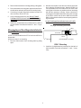
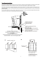
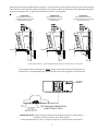
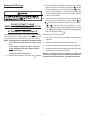
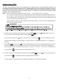
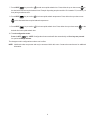
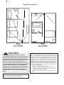
PTAC
WIRELESS KITS (DT01*, DS01*, DD01*)
INSTALLATION INSTRUCTIONS
AIR CONDITIONING SENSOR
DD01*
IO-644C~IO-644C~092007~4
DT01*
DS01*
The following installation instructions are for a typical installation.
Please contact your PTAC salesperson
for additional assistance and explanation prior to ordering materials or cutting openings.
USE ONLY ONE DD01* PASSIVE INFRARED MOTION SENSOR (PIR) DOOR SWITCH
COMBINATION DEVICE AND/OR ONE DS01* TO ONE DIGISMART PTAC UNIT.
ATTENTION INSTALLING PERSONNEL
As a professional installer you have an obligation to know the product better than the customer.
This includes all safety precautions and related items.
Prior to actual installation, thoroughly familiarize yourself with this Instruction Manual.
Pay special attention to all safety warnings. Often during installation or repair
it is possible to place yourself in a position which is more hazardous than when the unit is in operation.
Remember, it is your responsibility to install the product safely and to know it well enough
to be able to instruct a customer in its safe use.
Safety is a matter of common sense...a matter of thinking before acting.
Most dealers have a list of specific good safety practices...follow them.
The precautions listed in this Installation Manual are intended as supplemental to existing practices.
However, if there is a direct conflict between existing practices and the content of this manual,
the precautions listed here take precedence.
November 2007
IO-644D
is a trademark of Maytag Corporation and is used
under license to Goodman Company, L.P. All rights reserved.
®
Antenna Installation For DT01* Kit
A DT01* antenna must be installed to the PTAC to allow
operation of either the DS01* remote RF thermostat or a
DD01* combination PIR motion sensor and door switch.
Wire
Preparation
1. Disconnect power to the unit by unplugging the power
cord at the wall outlet or subbase, or disconnect power
at the fuse box or circuit breaker.
2. If the cabinet front is screwed to the chassis, remove the
1/4” screw (or screws) located behind the inlet grille. Pull
the inlet grille forward from the top of the grille to access
screw(s).
DT01* Mounting
5. Remove antenna cable and route cable through opening
in bottom of antenna housing.
6. Mount antenna housing with two screws as shown in
figure. (NOTE: The Amana® brand logo should be in the
lower right hand corner).
FRONT MOUNTING
HOLE
7. Plug wire harness from antenna into connector on the
control board to the right of the master switch, being
careful not to bend and/or break the wires when you
connect the cable to the PTAC. Gently push into place
with your thumb nails.
8. Restore power to the PTAC unit.
9. Reinstall the polymer room cover.
NOTE: The LED must be oriented at the top of the antenna
housing for proper unit operation.
3. Remove cabinet front from chassis by tilting the bottom
of the front forward, lifting slightly up and forward.
Thermostat Installation for DS01* Kit
NOTE: A DT01* must be installed in the PTAC unit for the
DS01* to be operable.
Skip these steps if not installing.
4. Mount the antenna as high up on the control panel as
possible and as far to the right as possible in a location
that will not interfere with the reinstallation of the PTAC
polymer room front. Mark holes for screw location. Remove antenna housing and drill two1/8”holes where
marked.
1. Select thermostat mounting location about five feet above
the floor, on an inside wall, out of direct sunlight, away
from sources of radiant heat (lamps, fireplaces, heating
and air conditioning equipment, etc.), away from windows or door to the outside, and avoid areas with poor
air circulation. Ensure location is out of the path of foot
traffic where a person might accidentally bump into the
thermostats and damage the device.
2
2. Mount the back plate on the door trim directly above the
door using the enclosed screws. Mount the DD01* as
low as possible on the door frame to be as close to the
moving part of the door as possible with out interfering
with the door opening or closing. Chose a location for
mounting the back plate that will provide good coverage
of the PIR for motion into the room. Make sure that the
DD01* will not interfere with the normal opening and closing of the door.
.2. Remove thermostat from mounting plate by pulling apart.
3. Place thermostat mounting plate against the wall at desired location and mark placement of mounting holes.
4. If mounting in drywall, tap plastic anchors into wall. For
other surfaces, drill a 3/16” hole.
5. Screw mounting plate to the wall. DO NOT SNAP
THERMOSTAT INTO PLACE UNTIL AFTER BINDING
PROCESS. See Binding Instructions on page 5.
DO NOT SNAP MOTION SENSOR IN PLACE UNTIL
AFTER BINDING PROCESS.
6. Install two (2) AAA batteries (included) into the back of
the thermostat. Terminals are marked “+” and “-” for polarity.
See page 5 for Binding Instructions.
DD01*
Mounting Sensor/Door Magnet Installation for
DD01* Kit
DOOR TRIM
A DT01* must be installed in the PTAC unit for the DD01* to
be operable.
DOOR
Skip these steps if not installing.
(CENTER MAGNET WITH DD01*)
1. Remove motion sensor from mounting plate by pulling
apart.
DD01* Mounting
3. Install two (2) AAA batteries (included) into the back of
the thermostat. Terminals are marked “+” and “-” for polarity.
3
Door Magnet Installation
Mount the door magnet holder on the front of the door where it will be as close as possible to the bottom of the motion
sensor but no more then 1/8" from the bottom center of the motion sensor (DD01*) when the door is closed.
Select the correct slot in the magnet holder (there are three slots) to obtain 1/2" from back of sensor mounting plate to the
center of the magnet. (If you can easily slide a business card between the magnet and the DD01* sensor, unit is properly
placed vertically.)
DOOR TRIM
Screw in place with the 2 screws provided. Open and close the door to make sure that the magnet holder and motion
sensor will not interfere with normal opening and closing of the door.
MAGNET MUST BE ½”
FROM THE SENSOR
MOUNTING PLATE
1/8” max.
MAGNET
DOOR
THE SPACE FROM THE TOP OF
THE MAGNET HOLDER AND THE BOTTOM
OF THE DD01*
CANNOT BE MORE THAN 1/8”.
The ideal spacing allows a business card to be easily placed
between the DD01* sensor and the magnet holder.
MAGNET HOLDER MAY EXTEND
ABOVE THE DOOR
(OR THE DD01* MAY EXTEND BELOW
THE DOOR FRAME)
TO ENSURE THE MAGNET IS NO MORE
THAN 1/8” FROM THE
BOTTOM CENTER OF THE SENSOR
MAGNET SLOTS
MAGNET HOLDER TOP
MAGNET HOLDER
TOP VIEW
SIDE
VIEW
INSTALL THE MAGNET IN
THE CORRECT SLOT.
½” FROM BACK EDGE OF
SENSOR MOUNTING PLATE
TO BACK OF MAGNET.
4
Select one of the three slots that places the magnet ½” from the sensor mounting plate on the door frame. See expamples
below. The door frame and door usually will not align. Place holder on the door and select the slot that places the magnet
as close as possible to the ½” depth from the back of the DD01* mounting plate.
POSITION C
Place magnet in Position C
in instances when the door extends
beyond the door trim.
DOOR TRIM
1/8” max.
1/8” max.
DOOR
DOOR
MAGNET
1/2”
MAGNET
1/2”
1/2”
ABOVE SHOWS MAGNET ½” FROM THE SENSOR MOUNTING PLATE IN DIFFERENT SLOT POSITIONS
Above graphics are for example only. Always measure and place the magnet in the proper slot
to obtain the 1/2” needed between the magnet and the sensor mounting plate on the door frame.
DD01*
½”
SENSOR
MOUNTING
PLATE
CENTER OF MAGNET
(IN HOLDER)
MUST BE ½” FROM THE
SENSOR MOUNTING PLATE
RECTANGULAR INDENTATION
ON BOTTOM OF DD01*
IMPORTANT NOTE: When properly installed, the rectangular indentation on the bottom of
the DD01* will line up with the center of the magnet.
Choose magnet position A, B or C to align the magnet 1/2” from the back of the DD01A*.
5
DOOR
1/8” max.
MAGNET
DOOR TRIM
POSITION B
Place magnet in Position B
in instances when the door
and frame align.
DOOR TRIM
POSITION A
Place magnet in Position A
in instances when the door trim
extends beyond the door.
Binding of RF Devices
2. Press and then immediately release the white tactile
button on the back of the DS01* thermostat.
should
now be displayed on the PTAC LED display. If
does
not show on the display in 1-2 seconds, then press and
release the white button a second time. Skip this step if
there is no thermostat.
3. Press and then immediately release the white tactile
button on the back of the DD01* motion sensor.
or
should now be displayed on the PTAC LED display.
DO NOT ATTEMPT TO BIND
MORE THAN ONE ROOM AT A TIME AT THE
SAME PROPERTY!!!
If
or
does not show on the display in 1-2 seconds, then press and release the white button a second
time. NOTE: If both a DD01* and a DS01* are being bound,
then the display will show
.
RF TRANSMITS THROUGH WALLS.
Skip if there is no motion sensor.
The wireless devices (DS01* and or DD01*) must be bound
to the PTAC DT01* control for proper in-room communication. Ensure the unit is powered but in the OFF position.
4. Press “OFF” on the PTAC touchpad to exit the binding
sequence.
NOTE: Both the DS01* and the DD01* must be bound to
the PTAC unit during the same “learn” operation.
5. Snap thermostat onto thermostat mounting plate.
6. Snap motion sensor onto motion sensor mounting plate.
If you need to rebind one device - then you
must rebind both devices during the same
learn mode event.
7. Configure the device or devices that were bound. See the
next section for configuration choices.
NOTE: If a wireless device is replaced or added, all
devices (including those previously bound) will need to
be bound/re-bound to the unit. See directions above.
All must be bound at one time.
1. Press and hold off button on the PTAC until
appears.
6
Configuration Settings
The PTAC control will automatically self-configure to work with the wall thermostat (DS01* Kit) if installed. The PTAC
control will automatically self-configure to activate pre-configured energy management routine when the DD01* is
installed and bound to the PTAC. Additionally, the setback times and setback temperatures can be changed using the
configuration settings. If you are using DP01* Front Desk Platform, the PTAC control will need to be configured to
identify its room number placement.
Standard and DS01* Configuration
To enter configuration feature mode:
Press and continue to hold the up and down
arrow keys and quickly press the OFF
key twice within
a two (2) second time frame. (On software versions 2.1 or lower - C1 will now be displayed. On version 2.5 or
higher - you will see “ - - “ displayed.) Once you are in the configuration program, you can use the HEAT button to
move UP the various configuration settings or the COOL button to move DOWN the configuration settings. The + or
- keys will move up or down the selectable codes that you can change for each configuration setting. Ensure that
you are in the proper configuration setting before pressing the + or - key as you may accidentally change a setting
that you did not intent to change.
The display will alternate between displaying the feature code
and the option code 0 (factory default setting). If
in version 2.5 or higher - press the HEAT button one time to get into C1 mode and then the display will alternate between C1 and 0 - the factory default. If an RF DS01* has been bound to the unit the display will alternate between
C1 and rE.The lower right dot on the display will flash.
Entering Room Number (Skip if not using DP01* Front Desk Platform)
1. The PTAC control can be set for a 4-digit room number. To select the first two digits (floor), press the HEAT
key until
appears, then press the up
down arrows to select the first two digits.
2. To select the last two digits of the room number, press the HEAT
and down
=
key until
appears, then press the up
down arrows to
.
Next to select the last two digits of the room number, press the HEAT
up and down
appears, then press the up
arrows to select the last 2 digits of the room number.
For example for Room “201”, press the HEAT
select “02”:
key until
arrows to select “01”:
=
.
7
key until
appears, then press the
Setback Temps - DD01*
The DD01* and the DigiSmart control can be programmed for 3 different times to activate temperature setbacks. The
current factory default temperature setbacks in v2.5 * software release are: 2º from set point in 30 minutes, 3º in one (1)
hour, and 6º in three (3) hours. For each time, you can select a setback temperature. The amount of setback is the amount
of degrees the control will operate from guest’s setting in degrees F. If a change to the factory default temperature settings
is desired, use the following instructions.
NOTE: When first entering the configuration mode, if you see “ - - ” then you have version 2.5 or higher.
You can verify the software version by starting with the unit in the OFF position, and while holding down the “+”
and “-” buttons , double click the COOL button and then release and push the FAN button within one second.
The unit display will scroll through all of the thermister temperatures and the last item displayed will bs CS
(current software) and you will see 25 for v2.5.
*Other software versions may have different factory setback defaults. Contact your PTAC representative to
determine factory default settings.
WARNING
4. To select first unoccupied set back temperature, press the HEAT
scroll to a previously viewed feature codes, press the COOL
Once you have scrolled to the
key until
feature code comes up. To
key.
feature, press either the up or down arrow
to scroll to the desired first unoc-
cupied setback temperature. Cooling example: 720 (guest set point) + 20 (Setback temperature) = 740 (operational
set point).
key to scroll to
first unoccupied setback time. The first unoccupied setback time is the time
5. Press HEAT
between when the control determines that the room is not occupied and when the control sets the operating set
point temperature back. The increments are in hours (.1 = 6 mins., .5 = 30 mins., 1 = 1 hour, etc.). Press either the
up or down arrow
to the desired first unoccupied setback time. c
6. To select second unoccupied setback temperature, press the HEAT
up or down arrow
key until
comes up. Press either the
to the desired second unoccupied setback temperature.
Cooling example: 720 (guest set point) + 40 (Setback temperature) = 760 (operational set point).
8
7. Press HEAT
key to scroll to
second unoccupied setback time. Press either the up or down arrow
to
the desired second unoccupied setback time. Example: Operating set point would be 760 instead of 72, one hour (1.0
hour) after guest leaves room.
8. Press HEAT
key to scroll to
third unoccupied setback temperature. Press either the up or down arrow
to the desired third unoccupied setback temperature.
9. Press HEAT
key to scroll to
third unoccupied setback time. Press either the up or down arrow
to the
desired third unoccupied setback time.
10.. To exit configuration mode:
Press the OFF
key. NOTE: Configuration feature mode will also automatically exit if no keys are pressed
for a period of two (2) minutes.
The changes made in configuration mode are now in effect.
NOTE: Additional codes are present and may be accessed within this menu. Contact the manufacturer for additional
information.
9
Typical Room Layouts
PTAC
PTAC
MOTION
SENSOR
MOTION
SENSOR
OUTSIDE
OUTSIDE
C A U TIO N
NOTE: This equipment has been tested and found to comply with the
limits for a Class B digital device, pursuant to Part 15 of the FCC
Rules. These limits are designed to provide reasonable protection
against harmful interference in a residential installation. This equipment
generates, uses and can radiate radio frequency energy and, if not
installed and used in accordance with the instructions, may cause
harmful interference to radio communications. However, there is no
guarantee that interference will occur in a particular installation. If this
equipment does cause harmful interference to radio or television
reception, which can be determined by turning the equipment off and
on, the user is encouraged to try to correct the interference by on or
more of the following measures:
- Reorient or relocate the receiving antenna.
- Increase the separation between the equipment and receiver.
- Connect the equipment into an outlet on a circuit different from
that to which the receiver is connected.
- Consult the dealer or an experienced radio/TV technician for
help.
This equipment is authorized for use under the
United States Federal Communication Commission
Rules and Regulations, Code of Federal Regulations
Chapter 47 part 15 and must be installed in accordance with the instructions provided in this document.
Failure to install or operate this equipment as instructed in this document could void the user's authority to operate the equipment. This equipment contains no user servicable parts. Any modification or
repairs to the internal components or to the antenna
configuration of the equipment without the express
written consent of Everex Communications, Inc.
could void the user's authority to operate the equipment.
NOTE: To comply with FCC RF exposure requirements in section
1.1307, a minimum separation distance of 20cm (8 inches) is
required between the equipment and all persons.
10
THIS PAGE INTENTIONALLY LEFT BLANK
11
Due to policy of continued product improvement, the right is reserved to change specifications and design without notice.
®
is a trademark of Maytag Corporation and is used under license to Goodman Company, L.P. All rights reserved.
Goodman Company, L.P.
5151 San Felipe, Suite 500 • Houston, TX 77056
www.amana-ptac.com
© 2005 - 2007 Goodman Company, L.P.
12