1
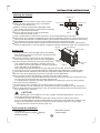
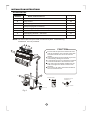
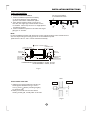
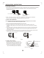
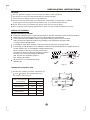
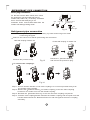
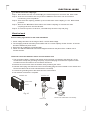
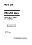
R410A SPLIT SERIES
FIXED SPEED QUICK COUPLING
Models
ECO902SQN
ECO1202SQN
ECO1802SQN
Before using your air conditioner, please read
this manual carefully and keep it for future reference.
BS PLUG WIRING
(For models up to 12000 Btu)
Wiring Instructions: Should it be necessary to change the plug please
note the wires in the mains lead are coloured in accordance with the
following code :
BLUE - NEUTRAL
BROWN LIVE
GREEN AND YELLOW - EARTH
As the colours of the wires in the mains lead of this appliance may not
correspond with the coloured markings identifying the terminals in your
plug, proceed as follows:
The BLUE wire is the NEUTRAL and must be connected to the terminal
which is marked with the letter N or coloured BLACK.
The BROWN wire is the LIVE and must be connected to the terminal
which is marked with the letter L or coloured RED.
The GREEN/YELLOW is the EARTH and must be connected to the
terminal which is marked with the letter E or or coloured GREEN OR
GREEN/YELLOW.
Always ensure that the cord grip is positioned and fastened correctly.
If a 13A (BS 1363) fused plug is used it must be fitted with a 13A fuse.
If in doubt consult a qualified electrician.
Wiring for a 13 Amp Plug (BS1363)
Please note. The Earth Terminal is marked with the letter E or
Symbol.
BS Plug Wiring
Earth
CONTENTS
SAFETY PRECAUTIONS
Warning .....................................................................................................................................2
Caution ......................................................................................................................................2
INSTALLATION INSTRUCTIONS
Selecting the location.........................................................................................................3
Accessories ........ .....................................................................................................................4
Indoor unit installation................................................................................................................5
Outdoor unit installation.............................................................................................................7
REFRIGERANT PIPE CONNECTION
Refrigerant pipe connection ......................................................................................................8
ELECTRICAL WORK
Electrical work .................. .......................................................................................................9
TEST RUNNING
Test running ...................... .....................................................................................................10
Read This Manual
Please read this installation manual completely before installing the air conditioner.
CAUTION
Contact an authorised service technician for repair or maintenance of this unit.
Contact an authorised installer for installation of this unit.
The air conditioner is not intended for use by minors or infirmed persons without supervision.
Young children should be supervised to ensure that they do not play with the air conditioner.
If the power cord is to be replaced, replacement work shall be performed by authorised personnel only.
Installation work must be performed in accordance with the national wiring Standards by authorised
personnel only.
1
SAFETY PRECAUTIONS
Read these SAFETY PRECAUTIONS carefully to ensure correct installation.
Precautions are classified as WARNING and CAUTION. Ensure all precautions are
observed as they are important to ensure your safety.
Failure to observe precautions may cause grave consequences.
WARNING
Failure to follow any WARNING is likely to result in grave consequences such as death or serious injury.
CAUTION
Failure to follow any CAUTION may result in grave consequences in some cases.
The following symbol used in this manual should be strictly oserved:
NEVER ATTEMPT.
WARNING
1) Installation should be carried out by a technically competent person, the dealer or specialist professional
Improper installation may cause water leakage, electrical shock, or fire.
2) Installation should be according to instructions given in this manual. Incomplete installation may cause
water leakage, electrical shock, or fire.
3) Only use the accessories, parts supplied and specified. Use of other parts may cause failure, water
leakage, electrical shock, or fire.
4) Install the air conditioner on a solid and firm base that can withstand ,the weight of the unit. An inadequate
base or incorrect installation may cause injury and damage if the unit falls off the base.
5) Electrical work must be carried out in accordance with the installation manual and the national electrical
wiring standards, regulations and code of conduct. A dedicated circuit must be used and never share the
power supply with another appliance. Insufficient capacity or incorrect electrical work may cause electrical
shock, or fire.
6) Use the specified cables for electrical connections between indoor and outdoor units. Firmly clamp the
cables so that no external stress is placed on the terminal. Incorrect connection or clamping may cause
terminal heating, electric shock or fire.
7) After connecting the interconnecting cables, properly arrange the cables and the cable covers so that there
is no undue pressure on the electrical covers or panels. Incorrect cover installation may cause terminal
overheating, electrical shock or fire.
8) When carrying out piping connection, take care not to let air substances other than the specified
refrigerant into refrigeration cycle. Any presence of air or other foreign substance in the refrigerant
circuit causes abnormal pressure rise or rupture, resulting in injury.
9) An earth and an earth leakage breaker must be installed. Do not earth the unit to a utility pipe, arrester
or telephone earth. Incomplete earth may cause electrical shock or fire. A high surge current from
lightning or other sources may cause damage to the air conditioner.
10) After the installation is completed, check to make sure that no refrigerant is leaking out. The refrigerant
is toxic gas if exposed to flames.
CAUTION
1) Do not install the unit in a place where there is any likely exposure to flammable gas leakage. If the
gas leaks and builds up around the unit, it may catch fire.
2) Carry out drainage piping according to the instructions of this manual. Inadequate piping may cause
flooding and leakage.
3) Ensure measures are taken so to prevent the outdoor unit from being used as a shelter by small animals
Small animals making contact with electrical parts can cause malfunction, smoke or fire.
2
INSTALLATION INSTRUCTIONS
Selecting the location
More than 15cm
Indoor unit
Do not expose the indoor unit to heat or steam.
More than 12cm
More than 12cm
Select a place where there are no obstacles
in front or around the unit.
Make sure that condensation drainage water
from Indoor unit can be conveniently routed away.
More than 2m
Do not install near a doorway.
Fig.1
Ensure that the space on the left and right
of the unit is more than 12cm.
Use a stud finder to locate studs to prevent unnecessary damage to the wall.
The indoor unit should be installed on the wall at a height of 2 metres or more from the floor.
The indoor unit should be installed allowing a minimum clearance of 15cm from the ceiling.
Any variations in pipe length may require adjustment to refrigerant charge.
There should not be any direct sunlight. Direct sunlight will fade the plastic cabinet and
affect its appearance. If unavoidable, sunlight prevention should be taken into consideration.
More than
30cm
Outdoor unit
More than 60cm
More than 30cm
Select a location solid enough to bear the weight
and vibration of the unit, where the operation noise
will not be amplified.
Choose a location where the hot air discharge or
noise will not cause annoyance to the neighbours. More than
Ensure that the clearance around the back of the 200cm
More than
unit is at least 30cm,left side is at least 30cm, the
60cm
front of the unit is at least 200cm and the connection
Fig.2
side (right side) is at least 60cm.
There must be sufficient spaces for carrying the unit into and out of the site.
The site must be free from the possibility of flammable gas leakage in a nearby place.
Avoid places near a bedroom and the like, so that the noise will not be an annoyance.
Ensure any local authority permission is sought where applicable.
Do not place animals and plants in the path of the air inlet or outlet.
Install units, power cords and cables at least 3 meter away from television and radio sets.
This is to prevent interference to images and sounds.
In coastal areas or places with salty atmosphere of sulfate gas, corrosion may shorten
the life of the air conditioner.
If the outdoor unit is installed on a roof structure, be sure to level the unit.
Ensure that the unit is installed in an accessible location to enable servicing and repair.
Since drain flows out of the outdoor unit, do not place anything under the unit which must
be kept away from moisture.
CAUTION
When operating the air conditioner in a low outdoor ambient temperature, be sure to
follow the following instructions:1) Install the suction side of the unit facing the wall to prevent exposure to wind.
2) It is recommended to install a baffle plate on the air discharge side of the outdoor unit.
3)Select an installation site where the snow will not affect the unit such as at a high
enough level to avoid snow burying the unit.
Tools needed for installation:
Screwdriver
Electric drill,Hole core drill (
Measuring tape
Gas-leak detector
Thermometer
90mm)
3
INSTALLATION INSTRUCTIONS
Accessories
Number
Q ty
Name of Accessories
1
Installation Plate
1
2
Clip Anchor
8
3
Self-tapping Screw A - ST3.9X25
8
4
1
5
Seal(see page 8 for details)
Drain Plug(see page 8 for details)
6
Remote controller
1
7
Self-tapping Screw B - ST2.9X10
2
8
Remote controller holder
1
1
Note: The above parts are provided,certain other parts needed during
installation are not provided.
3
2
15cm abov
1
CAUTION
bov
Ensure that the space around the left and
right of the indoor unit is at least 12cm with
a minimum clearance of 15cm from the
ceiling.
Use a stud finder to locate studs to prevent
unnecessary damage to the wall.
A minimum pipe run of 3 metres is required
to minimise vibration & excessive noise.
The indoor unit should be installed on the
wall at a height of at least 2 metres from
the floor .
Two of the A, B and C directions should be
free from obstructions.
e
12cm above
Air F
ilter
2 m above
ma
A
Air Outlet
30c
ma
bov
60cm above
12c
e
30c
e
e
bov
ma
Remote Controller
6
B
200
cm
v
abo
Self-tapping screw B
ST2.9x10-C-H
SET TEMPERATURE ( C)
FAN
HIGH
MED
LOW
AUTO
COOL
DRY
HEAT
e
TEMP
60c
ma
MODE
bov
e
SWING
C
ON/OFF FAN SPEED
SLEEP
RESET LOCK
AIR
DIRECTION
7
8
TIMER ON
TIMER OFF
LED
DISPLAY TURBO
Remote controller
holder
Stop Valve Cover
Fig.3
.
4
INSTALLATION INSTRUCTIONS
Indoor unit installation
Correct orientation
of Installation Plate
1. Fit the Installation Plate
1. Fit the installation plate horizontally
on structural parts of the wall with
spaces around the installation plate.
2. If the wall is made of brick, concrete or
the like, drill eight (8) 5mm diameter holes
in the wall. Insert Clip anchor for appropriate
mounting screws.
3. Fit the installation plate on the wall with eight
(8) type “A” screws.
Fig.4
Note:
Fit the Installation Plate and drill holes in the wall according to the wall structure
and corresponding mounting points on the installation plate.
(Dimensions are in “mm” unless otherwise stated)
102
Left rear side
refrigerant
pipe hole 90
52
58
52
120mm or
more to wall
150mm or more to ceiling
Installation plate
270
Indoor unit outline
780
120mm or
more to wall
Right rear side
refrigerant
pipe hole 90
ECO902SQN / ECO1202SQN : A:780 , B:270
ECO1802SQN : A:920 , B:270
Fig.5
Wall
2. Drill a hole in the wall
Outdoor
Indoor
5-7mm
1. Determine hole positions according to
the diagram detailed in Fig.5. Drill
one (1) hole ( 90mm) slanting slightly
to outdoor side.
2. Always use wall hole conduit when
drilling metal grid, metal plate or the like.
Fig.6
5
INSTALLATION INSTRUCTIONS
3. Drainage Installation
1. Run the drain hose sloping downward to ensure condensation water is being drained externally,
any rise in the drain hose will prevent condensation water to flow externally on gravity as
illustrated below (Fig. 7).
Condensation Water
Do not form a rise
Do not put the hose
end into water
Fig.7
2. When connecting extension drain hose, insulate the connecting part of extension
drain hose with a shield pipe, avoiding any slack on the drain hose.
4. Indoor unit installation
Note: Route the flexi hose with female half coupling through the hole in the wall
from the rear of the indoor unit (right) or (left).
1. Pass the female half coupling through the hole in the wall.
2. Position the upper claw (at the back of the indoor unit) on the upper hook of the
installation plate, gently rock the indoor unit from side to side to check that it is securely
hooked.
3. Temporarily place a cushioning material between the indoor unit and the wall as illustrated
below to make it easier to completely route the flexi hose through the wall. Remove the
cushioning material.
4. Gently push the lower part of the indoor unit up against the wall, then gently rock the indoor
unit from side to side, up and down to check that it is securely hooked.
Upper hook
Cushioning
material
Lower hook
Fig.8
5. Piping and wrapping
Indoor unit
Bundle the tubing, connecting cable with
tape securely and evenly as shown in Fig.9.
Because the condensed water from the
indoor unit is gathered in condensation
tray and should be piped out externally.
Connective
cable
Condensation tray
Pipe room
Connective
pipe
Wrapping belt
Drain hose
Fig.9
6
INSTALLATION INSTRUCTIONS
CAUTION
Do not allow the pipin g to let out from the back of the indoor unit.
Be careful not to let the drain hose slack or bend sharpley.
The connective pipes must be heat insulated.
Be sure that the drain hose is located at the lowest side of the bundle. Locating
at the upper side can cause condensation tray to overflow inside the unit.
Never intercross nor intertwist the power wire with any other wiring.
Run the drain hose sloping downward to drain out the condensed water smoothly.
Outdoor unit installation
Outdoor installation precaution
Install the outdoor unit on a solid and level base to prevent excessuve noise level and vibration.
Determine the air outlet direction where the discharged air is not blocked.
In the case that the installation place is exposed to strong wind such as a seaside,
make sure the fan operates properly by putting the unit lengthwise along the wall
or using a dust or shield plates.
In coastal or windy area, install the unit to prevent the exposure to strong winds.
If mounting on wall brackets, the installation brackets must be suitable for the weight and size
out the outdoor unit. The installation wall should be solid
brick, concrete or the same intensity construction,
or actions to reinforce, damping supporting should
Strong
be taken. The connection between brackets,
wind
wall and the air conditioner must be
firm, stable and reliable.
Be sure there is no obstacle blocking
radiating air.
Fig.10
Settlement of outdoor unit
Anchor the outdoor unit with a bolt and nut
10 or 8 tightly and horizontally on a
concrete or solid mount.
A
Air inlet
Air inlet
700x535x235
458
250
685x430x260
460
276
780x540x250
549
276
760x590x285
530
290
845x695x335
560
335
B
Outdoor unit dimension Mounting dimensions
mm(WxHxD)
A(mm)
B(mm)
Air outlet
Fig.11
7
REFRIGERANT PIPE CONNECTION
Drain plug installation
Fit the seal into the drain elbow, then insert
the drain plug into the base pan hole of
outdoor unit, rotate 90 to securely assemble
them. Connect the drain plug to an
extension drain hose to drain water from the
outdoor unit during heating mode.
Seal
Drain Plug
Base pan hole of
outdoor unit
Seal
Drain pipe
Fig.12
Refrigerant pipe connection
CAUTION: For your safety, always wear safety eye wear and work gloves when
connecting the pipes.
Remove the valve cover before performing the connection.
Male half coupling of indoor unit
Female half coupling of outdoor unit
Retract the Release Sleeve
and remove the protective plug.
Remove the protective cap.
Fig.13
To connect the couplings:
Fig.14
Step 1: Ensure that the handle on the male coupling is in a reclined position away from
the mating male coupling.
Step 2: Retract the Release Sleeve on female coupling, insert the male coupling
located on the indoor unit into the female coupling.
Step 3: Release the Release Sleeve to the lock the male coupling into places.
Step 4: Fold the male coupling handle towards the female coupling half and push until the
handle seals behind the Release Sleeve and flat against the entire coupling
assembly.
8
ELECTRICAL WORK
To disconnect the couplings:
Step 1: Shut down the A/C unit and unplug the electrical power cord from the wall outlet.
Step 2: Wait five minutes for the line pressure between the indoor unit and outdoor
condensing unit to equalize.
Step 3: Pull the male coupling handle up and toward the male coupling to the full back
position.
Step 4: Retract the Release Sleeve on the female coupling to release the male
coupling half from the female half.
Step 5: To seal and protect from dust, reinstall the protective cap and plug.
Electrical work
Electric safety regulations for the initial Installation
1. Power voltage should be in the range of 90%~110%of rated voltage.
2. The creepage protector and main power switch with a 1.5 times capacity of Max. Current of the unit
should be installed in power circuit.
3. Ensure the air conditioner is grounded well.
4. Follow the attached Electrical Connection Diagram located on the panel of the outdoor unit to
connect the wire.
Electrical connection between indoor unit and outdoor unit
1. The connection cables of indoor and outdoor units have been connected to the terminals on the
control board except the grounding wire(Y/G), only the white plug connectors are exposed. Check
to make sure the connection to the connectors are secure.
2. Remove the control cover from the outdoor unit by loosening the screw.
3. Hold the indoor plug connector and connect to the mating plug connector located on the outdoor unit
Secure the cable onto the control board with the cord clamp.
4. Connect the grounding wire to the terminal on the control board.
5. The electrical connection is complete.
Outdoor unit
Outdoor unit
1
1
2(N) 3
2(N) 3
4
4
Control Cover
Screw
Plug
connector
Y/G
Fig.15
Secure the cable with cord clamp.
Indoo r unit
9
ELECTRICAL WORK
Model
<12000Btu/h
>12000Btu/h
Input Rated Amp
(Switch/Fuse)
Power supply
220-240V~ 50Hz
or
220-230V~ 60Hz
13A
20A
NOTE: The supply voltage can not be less than the rate voltage of the air conditioner.
CAUTION
CAUTION
CAUTION
After the confirmation of the above conditions, prepare the wiring as follows:
1) Be sure to use a dedicated power circuit specifically for the air conditioner.
2) The screws fastening the wiring in the casing of electrical fittings may become
loose from vibrations and transportation. Tighten all terminal screws securely.
Check and make sure they are tightly
3) Check the specification of power source is correct.
4) Confirm that electrical capacity is sufficient.
5) Make sure the starting voltage is maintained at more than 90 percent of the rated
voltage marked on the name plate.
6) Always install an earth leakage circuit breaker in a wet or moist area.
7) A vibration of a magnetic switch may damage the contact point, causing fuse
break to fail or the normal function of an overload to fail.
8) Do not turn on the safety breaker until all work is completed.
9) Use an all-pole disconnection type breaker with at least 3mm between the contact
point gaps.
Test running
Perform test operation after completing gas leak check at the pipe connections and
electrical safety check.
Check that all tubing and wiring have been properly connected.
Check that the coupling connection on the outdoor unit is completely secure and aligned.
1. Connect the power, press the ON/OFF button on the remote controller to turn the unit on.
2. Use the MODE button to select COOL, HEAT, AUTO and FAN to check if all the functions
works well.
3. When the ambient temperature is too low(lower than 17OC), the unit cannot be tested via
the remote controller to run at cooling mode.
Carry out a manual testing via a manual control button located in the indoor unit (as
illustrated below). The remote controller must be disabled first.
To locate the manual control button, open the indoor unit panel by holding the panel
sides and lifting the panel up to an angle until it remains fixed with a clicking sound.
Press the Manual control button to select AUTO or COOL, this will force the operation
of AUTO or COOL(see User Manual for details).
4. The test operation may last about 30 minutes.
Manual control
button
AUTO/COOL
10
MEMO
Date of installation:
Purchased from (Dealer Name):
Date of purchase:
Model number:
Serial number:
ONE (1)YEAR LIMITED WARRANTY
Save This Warranty Information
EcoAir guarantees this product free from defects in materials and workmanship
for a period of one (1) year from the date of purchase, limited to parts only.
Faults arising from a faulty installation is specifically excluded.
This unit must be operated under conditions as recommended, at voltages
indicated on the unit. Any attempts made to service or modify the unit by
unqualified technician, will render this WARRANTY VOID. The actual product
may differ slightly from the illustration. This warranty is in addition to, and does
not affect, your statutory rights.
For further information, please contact 020 8459 2458.
Copyright Reserved