1
M-xxx SERIES
PRODUCT DESCRIPTION
October 26th, 2000
Sommaire
1.
INTRODUCTION................................................................................................................................................................ 5
1.1
JUNIPER NETWORKS : TECHNOLOGY OVERVIEW................................................................................................5
1.1.1
Challenge: Reliability with Rapid Growth ................................................................................................5
1.1.2
Juniper Networks: Enabling IP Network Growth.........................................................................................5
1.1.3
M5, M10, M20, M40, M160 : Foundation for the Internet Core ................................................................5
The Internet Processor: Optical-Speed Packet Forwarding...........................................................................................6
1.2 JUNOS INTERNET SOFTWARE: TRAFFIC ENGINEERING AND CONTROL.........................................7
1.2.1
JUNOS Internet Software: Class-of-Service Flexibility ..............................................................................7
1.2.2
Random Early Detection for Congestion Management................................................................................7
1.3 ADDRESSING SCALABILITY CONCERNS.......................................................................................................8
1.4 THE JUNIPER NETWORKS P ROPOSAL............................................................................................................8
1.4.1
Backbone Routing...........................................................................................................................................9
1.4.2
Peering..............................................................................................................................................................9
1.4.3
Traffic Management via MPLS......................................................................................................................9
1.5 ACTIVE PARTICIPATION IN STANDARDS BODIES........................................................................................9
1.6 JUNIPER NETWORKS INTERNET BACKBONE ROUTERS ADVANTAGES ............................................10
2.
THE JUNIPER NETWORKS INTERNET BACKBONE ROUTER PLATFORMS .....................................12
2.1
2.2
2.3
2.4
2.5
THE M20, M40 AND M160 INTERNET CORE BACKBONE ROUTERS..............................................12
THE M20 HARDWARE SYSTEM ....................................................................................................................14
THE M40 HARDWARE SYSTEM ....................................................................................................................20
THE M160 HARDWARE SYSTEM ..................................................................................................................27
M20, M40 AND M160 INTERNAL ARCHITECTURE...............................................................................36
2.5.1
2.5.2
2.5.3
2.5.4
2.5.5
2.5.6
2.5.7
Internal Architecture of the M20 and M40..................................................................................................36
Differences between the M20 and the M40.................................................................................................37
Internal Architecture of the M160................................................................................................................37
Switching architecture ...................................................................................................................................40
The Routing Engine.......................................................................................................................................41
The Forwarding Table...................................................................................................................................42
Switching Performance .................................................................................................................................42
2.5.8
The Internet Processor II ASIC...............................................................................................................43
2.6 CONGESTION CONTROL...................................................................................................................................45
2.6.1
Hardware Monitoring of Input Traffic for Congestion..............................................................................45
2.6.2
Monitoring of Output Queue Congestion and Dropping Packets..............................................................45
2.6.3
Setting congestion control variables ............................................................................................................46
2.7 CLASS OF SERVICE ............................................................................................................................................47
2.7.1
Implementation of Class Of Service ............................................................................................................47
2.7.2
Application of Class Of Service...................................................................................................................49
2.7.3
Traffic Policing.............................................................................................................................................49
2.7.4
ATM Traffic Shaping....................................................................................................................................51
2.8 CLOCK SOURCE ..................................................................................................................................................53
2.9
THE M5 AND M10 INTERNET ROUTERS.............................................................................................................54
2.9.1
The Forwarding Engine Board...................................................................................................................54
2.9.2
Routing Engine.............................................................................................................................................55
2.9.3
Interfaces .......................................................................................................................................................55
2.9.4
Compact Size for Space Efficiency...........................................................................................................56
2.9.5
Power Supplies .............................................................................................................................................56
2.9.6
Cooling System ............................................................................................................................................57
2.9.7
The M10/M5 Craft Interface ......................................................................................................................57
2.9.8
Field Replaceable Units ..............................................................................................................................57
2.9.9
Target Applications......................................................................................................................................57
2.10 P RODUCTS SPECIFICATIONS...........................................................................................................................59
Page 2 /148
2.10.1
2.10.2
2.10.3
2.10.4
2.10.5
2.10.6
2.10.7
2.10.8
2.10.9
2.10.10
2.10.11
2.10.12
2.10.13
2.10.14
2.10.15
2.10.16
2.10.17
2.10.18
2.10.19
2.10.20
3.
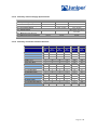
M20 Specifications........................................................................................................................................59
M40 Specifications........................................................................................................................................61
M160 Specifications......................................................................................................................................63
Summary of Power Supply Specifications ..............................................................................................65
Summary of Interface and Port Densities ................................................................................................65
Summary of Interfaces Types and Supported M-xxx Router...............................................................66
Index of Interface Specification Datasheets ............................................................................................67
Flexible PIC Concentrator Cards for Juniper Networks Routers.........................................................68
POS Interfaces Specifications....................................................................................................................71
ATM Interfaces Specifications..............................................................................................................74
DS-3 Physical Interface Cards for M-xxx Routers ............................................................................78
E3 Physical Interface Cards for M-xxx Routers.................................................................................78
Channelized OC-12 to DS-3 Physical Interface Card .......................................................................79
Channelized DS-3 Physical Interface Card for M-series Routers ...................................................79
T1 Physical Interface Card for M-series Routers ...............................................................................80
E1 Physical Interface Card for M-series Routers ...............................................................................80
Fast Ethernet Physical Interface Card for M-series Routers ............................................................81
Gigabit Ethernet Physical Interface Cards for M -series Routers.....................................................81
Tunnel Services Physical Interface Card .............................................................................................83
Frame Relay Specifications....................................................................................................................84
JUNOS SOFTWARE SPECIFICATIONS..................................................................................................................85
3.1
JUNOS SOFTWARE A RCHITECTURE...................................................................................................................85
3.1.1
JUNOS Architecture ....................................................................................................................................85
3.1.2
JUNOS Routing Architecture ....................................................................................................................87
3.1.3
Junos Routing Protocols..............................................................................................................................90
3.2 IP ROUTING .........................................................................................................................................................91
3.2.1
Static Routing.................................................................................................................................................92
3.2.2
OSPF...............................................................................................................................................................92
3.2.3
IS-IS ................................................................................................................................................................92
3.2.4
BGP-4 .............................................................................................................................................................93
3.2.5
Routing Policies.............................................................................................................................................96
3.2.6
IP Multicast Support....................................................................................................................................100
3.2.7
CIDR .............................................................................................................................................................101
3.2.8
Broadcast......................................................................................................................................................101
3.2.9
IP Tunneling.................................................................................................................................................102
3.2.10
Load sharing on parallel links.....................................................................................................................102
3.2.11
Equal Cost Load Balancing with The Internet Processor II.....................................................................103
3.3 MPLS FOR TRAFFIC ENGINEERING...........................................................................................................104
3.3.1
LDP ...............................................................................................................................................................105
3.3.2
Tunneling LDP LSPs in RSVP LSPs.........................................................................................................106
3.4 VIRTUAL P RIVATE NETWORKS...................................................................................................................107
3.4.1
Layer 2 Virtual Private Networks ...........................................................................................................107
3.4.2
Layer 3 IP VPN Strategy ..........................................................................................................................108
3.5 SECURITY............................................................................................................................................................111
3.5.1
Firewall Filters .............................................................................................................................................111
3.5.2
Hardware-based Packet Filtering...............................................................................................................111
3.5.3
Routing Engine Firewall .............................................................................................................................112
3.5.4
Protocol Authentication...............................................................................................................................113
3.5.5
User Authentication.....................................................................................................................................113
3.5.6
Audit trails of login attempts and command history.................................................................................114
3.6 JUNOS SOFTWARE SPECIFICATIONS........................................................................................................116
4.
AVAILABILITY...............................................................................................................................................................119
4.1
4.1.1
4.1.2
4.1.3
4.1.4
REDUNDANCY CONCERNS............................................................................................................................119
Causes of Failure .........................................................................................................................................119
The Fundamental Premise...........................................................................................................................120
The Juniper Approach .................................................................................................................................120
Operator Errors ............................................................................................................................................120
Page 3 /148
4.1.5
4.1.6
4.1.7
Software Errors............................................................................................................................................120
Hardware Errors...........................................................................................................................................121
Network Level Reliability...........................................................................................................................122
4.2 HARDWARE REDUNDANCY ..........................................................................................................................122
4.2.1
Redundancy of Central Control and Processing .......................................................................................122
4.2.2
Redundant Routine Engine .........................................................................................................................122
4.2.3
Redundant System and Switching Board ..................................................................................................124
4.2.4
Redundant power supplies ..........................................................................................................................125
4.2.5
Redundant chassis fans................................................................................................................................125
4.2.6
Hot swap and modularity ............................................................................................................................125
4.3 LOGICAL REDUNDANCY................................................................................................................................125
4.3.1
Software Redundancy..................................................................................................................................125
4.3.2
Automatic Protection Switching (APS).....................................................................................................126
4.3.3
Virtual Router Redundancy Protocol (VRRP) ..........................................................................................126
4.3.4
MPLS Traffic Engineering and Fast Reroute............................................................................................126
4.4 MEAN-TIME BETWEEN FAILURE DATA FOR JUNIPER NETWORKS ’ COMPONENTS..................126
4.4.1
Mean-Time Between Failure Data for the M20 and M40...................................................................126
4.4.2
Mean-Time Between Failure Data for the M160..................................................................................127
5.
MANAGEABILITY.........................................................................................................................................................132
5.1
CONFIGURATION AND MANAGEMENT.......................................................................................................132
5.1.1
5.1.2
5.1.3
5.1.4
Front Panel and Craft Interface..................................................................................................................132
JUNOS Command Line Interface..............................................................................................................132
Telnet access ................................................................................................................................................133
Documentation and On -line (Long Help) Documentation.......................................................................133
5.2 SOFTWARE DOWNLOAD................................................................................................................................133
5.3 SOFTWARE STARTUP AND EMERGENCY RECOVERY PROCEDURES .................................................133
5.4 SYSTEM UPGRADE............................................................................................................................................134
5.4.1
Routine maintenance procedures................................................................................................................134
5.5 FAULT MONITORING.......................................................................................................................................135
5.5.1
SNMP Traps.................................................................................................................................................135
5.5.2
Alarm Conditions.........................................................................................................................................135
5.5.3
Syslog...........................................................................................................................................................136
5.5.4
End-to-end loopback diagnostics ...............................................................................................................136
5.5.5
Environmental monitoring..........................................................................................................................137
5.6 STATISTICAL ANALYSIS ................................................................................................................................138
5.6.1
Storage of Sampling Data ...........................................................................................................................138
5.6.2
Transfer of Sampling File/Interfacing with Analysis Tools ....................................................................138
5.6.3
Cflowd aggregation support in sampling ...............................................................................................138
5.6.4
On-line Sampling Analysis Tools ..............................................................................................................138
5.6.5
Sampling Application: Characterizing Traffic Flows...............................................................................138
6.
INTEROPERABILITY ..................................................................................................................................................140
7.
PERFORMANCE.............................................................................................................................................................141
Page 4 /148
1. INTRODUCTION
1.1
1.1.1
Juniper Networks : Technology Overview
Challenge: Reliability with Rapid Growth
Internet backbone networks are constantly under pressure to scale rapidly in
order to accommodate customer demands for faster response times and greater
reliability. At the same time, routing and packet forwarding technologies have
lagged Internet growth. This lag has increased the operational challenge of
maintaining stability in the face of rapid network growth. As Internet backbone
networks move to ever-faster optical rates, a new generation of routing device is
required that can provide the necessary combination of optical-rate forwarding
and operational control to enable providers to scale their networks rapidly and
reliably.
1.1.2
Juniper Networks: Enabling IP Network Growth
With the delivery of ht e M-xxx Internet Backbone Routers and JUNOS Internet
Software, Juniper offers new levels of control and performance for Internet
Protocol backbone providers. A unique combination of best-in-class Internet
protocol developers and expert ASIC hardware designers will enable Juniper to
continue to deliver high-performance routing and forwarding systems that
address the scalability, performance, and reliability necessary to support the
Internet’s continuous and explosive growth. In addition, extensive experience in
manufacturing and supporting routing systems for fast-growing Internet protocol
backbone network providers gives Juniper a solid understanding of the scaling
challenges of the Internet and a unique ability to help IP network providers scale
to meet demand today and into the future.
Juniper’s Internet Software, JUNOS T M, offers best-of-class implementations of all
Internet routing protocols, including BGP4, OSPF, IS-IS, MPLS, and multicast.
The quality of the protocol implementations reflects the experience and expertise
of the developers, who all have taken active roles in defining and authoring
numerous Internet protocol drafts and RFCs (Request for Comments) in the IETF
(Internet Engineering Task Force), and who all have extensive experience in
writing and supporting code that forms the heart of the Internet. Juniper has the
experience base to understand both what is necessary to implement Internet
scale protocols and to support such protocols in a mission critical environment.
The Juniper software experts will continue to provide focused standards
leadership for the benefit of customers, who require a partner that understands
and can facilitate protocol implementations to scale at the Internet’s and large
enterprises’ existing growth rates.
1.1.3
M5, M10, M20, M40, M160 : Foundation for the Internet Core
The M-xxx Internet backbone routers from Juniper Networks have been designed
specifically for the specialized needs of high-growth Internet backbone providers,
featuring market-leading packet-forwarding horsepower, unparalleled port density
and port flexibility, and best-in-class Internet software. The M-xxx deliver the
speed required for providers to grow their backbones to OC-48 speeds, while
also providing the necessary traffic engineering tools to ensure greater control
over traffic and use of network capacity. In addition, the M-xxx make the most
efficient use of precious point-of-presence (POP) rack space, offering the highest
port density and highest performance per rack-inch on the market today. The Mxxx low power consumption also offer best-in-class efficiency of POP power
consumption. Finally, to ensure rock-solid network stability, the M-xxx have been
engineered to handle the exceptionally stressful conditions that arise under peak
traffic loads and link failures.
The M160™ Internet backbone router is the first routing platform of its kind,
offering true wire-rate performance for up to 16 OC-192c/STM-64 or 64 OC48c/STM-16 Physical Interface Cards (PICs) per rack. The M160
breakthrough ASICs translate optical bandwidth into new, differentiated IP
services. Running the same JUNOS™ Internet software and delivering the
same services as the already proven M20™ and M40™ Internet backbone
routers, you can be assured of an efficient, easily scalable, end-to-end
solution when building out your infrastructure. The M160 platform is ideal for
large networks requiring predictable performance for feature-rich
Page 5 /148
infrastructures. It is purpose built for large backbone cores, with features
enabled for future migration to the backbone edge. The M160 router offers
aggregate route lookup rates in excess of 160 Mpps for wire-rate forwarding
performance and an aggregate throughput exceeding 160 Gbps. It is the first
router to offer a truly concatenated OC-192c/STM-64 PIC with throughput of
10-Gbps full duplex and market-leading port density with up to 32 OC48c/STM-16 PICs per chassis or 64 per rack. Its exceptional ASIC design
and production-proven routing software put you in the forefront of nextgeneration IP technology.
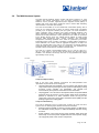
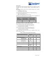
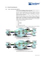
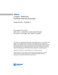
In September 2000, Juniper Networks launched 2 new platforms : the M5
and M10 Internet Routers. The M10/M5 is a compact, high-performance
routing platform based on the ASIC-based M160/M40/M20 forwarding
architecture (including the Internet Processor II) and JUNOS Internet
software. As an extension of the M160/M40/M20 product line, the M10/M5 is
targeted at a variety of Internet applications, including :
§
high-speed access,
§
public and private peering,
§
content sites,
§
and backbone core networks.
Only 5.25 inches in height, the M10/M5's compact design brings tremendous
performance and port density in very little rack space.
Sept. 2000
M10
Sept. 1998
M40
Nov. 1999
M20
Mar. 2000
M160
Sept. 2000
M5
The Internet Processor: Optical-Speed Packet Forwarding
The M-xxx deliver optical-speed forwarding using Juniper-developed, cuttingedge ASIC designs. The heart of the M-xxx Packet Forwarding Engine (PFE) is
the Internet Processor. With over one million gates, the Internet Processor
represents the largest route look-up ASIC ever implemented on a router platform.
Providing a lookup rate of over 40 million packets per second, the Internet
Processor is also the fastest route lookup engine on the market today, capable of
processing data for throughput rates in excess of 40 gigabits per second (Gbps).
The Internet Processor also features prefix accounting mechanisms at rates in
excess of 20 Mpps.
All lookup rates reflect longest-match route table lookups for all packets and all
lookups are performed in hardware. There is no caching mechanism – and hence
no risk of cache misses — in the system. In addition, the forwarding table can be
updated without affecting forwarding rates. The Internet Processor is
programmable to support up to four different forwarding tables — layer 2 and/or
layer 3 — simultaneously. Supported forwarding protocols currently include IPv4
(unicast and multicast) and MPLS. Finally, the Internet Processor maintains its
performance regardless of length of lookups or table size. As Internet bandwidth
demand grows, the Internet Processor and PFE architecture will be the
fundamental building block for future Juniper platforms.
Page 6 /148
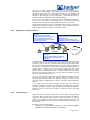
1.2
JUNOS Internet Software: Traffic Engineering and Control
Protocols and software tools, which are used to control and direct network traffic,
are critical to an Internet backbone routing solution. In fact, software control is
made more important by the fact that the size and complexity of backbone
networks are increasing at a time when service providers are looking to
differentiate themselves through value-added service offerings. To provide a
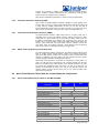
foundation for control, the M-xxx Routing Engine features JUNOS Internet
Software, which offers a full suite of Internet-scale, Internet-tested routing
protocols.
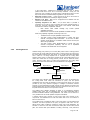
Operating
Operating System
System
Security
SNMP
Chassis Mgmt
Interface Mgmt
Protocols
The JUNOS software features implementations of the BGP4, IS-IS, OSPF,
MPLS, DVMRP, and PIM protocols. A Juniper design team developed all
protocols in-house with extensive experience in addressing the scaling issues of
rapidly growing Internet backbone providers.
JUNOS software features a modular design, with separate programs running in
protected memory space on top of an independent operating system. Unlike
monolithic, unprotected operating system designs, which are prone to systemwide failure, the protected, modular approach improves reliability by ensuring that
modifications made to one module have no unwanted side effects on other
sections of the software. In addition, having clean software interfaces between
modules facilitates software development and maintenance, enabling faster
customer response and delivery of new features.
The JUNOS software also provides a new level of traffic engineering capabilities
with its implementation of Multi-Protocol Label Switching (MPLS). Developed in
conjunction with the emerging IETF standard, Juniper MPLS offers enhanced
visibility into traffic patterns and the ability to control the path traffic takes through
the network. Path selection enables providers to engineer traffic for efficient use
of network capacity and avoidance of congestion. MPLS and traffic engineering
will become a crucial tool for providers as they scale their networks.
The JUNOS software features include:
1.2.1
§
Full-scale implementation of BGP4 with route reflectors, confederations,
communities, route flap damping, and MD5 BGP authentication
§
A flexible and scalable policy implementation for filtering and modifying route
advertisements
§
Scalable IS-IS and OSPF for filtering and modifying route advertisements
§
PIM Sparse Mode and Dense Mode, DVMRP, MSDP and IGMP for multicast
§
MPLS with LDP and RSVP extensions for traffic engineering
§
Configuration management features for enhanced usability
§
Secure remote access with SSH (USA version only)
JUNOS Internet Software: Class-of-Service Flexibility
The Juniper routers have been designed for a variety of class-of-service
applications. The queuing mechanism is based on a weighted round-robin
selection among four queues on outgoing interfaces. Three drop profiles per
Flexible PIC Concentrator (FPC) are available to control the rate of packet drops
based on utilization of buffer capacity. A Random Early Detection (RED)
algorithm handles congestion management based on these profiles, ensuring the
proper execution of the provider’s policy.
The Juniper routers give providers full flexibility in setting class-of-service levels
for customers. Service levels can be based on destination address, physical input
port, IPv4 precedence bits, MPLS CoS bits, virtual circuit, next-hop address,
and/or encapsulation type. The Juniper routers also offer the ability to overwrite
the precedence of incoming packets. In addition, a token-bucket mechanism has
been implemented on input to allow rate policing, enabling CIR (Committed
Information Rate)-type service for customers. Finally, a leaky-bucket mechanism
provides rate shaping on output ports.
1.2.2
Random Early Detection for Congestion Management
Random Early Detection (RED) provides network operators with the ability to
flexibly specify traffic handling policies to maximize throughput under congestion
conditions. RED works in conjunction with robust transport protocols (e.g. TCP) to
intelligently avoid network congestion by implementing algorithms which:
Page 7 /148
1.3
§
Distinguish between temporary traffic bursts that can be accommodated by
the network and excessive offered load likely to swamp network resources.
§
Work cooperatively with traffic sources to avoid TCP slow start oscillation
that can create periodic waves of network congestion.
§
Provide fair bandwidth reduction to reduce traffic sources in proportion to the
bandwidth being utilized. Thus, RED works with TCP to anticipate and
manage congestion during periods of heavy traffic to maximize throughput
via managed packet loss.
§
Are implemented in hardware in such a manner that entire packets need not
be stored in output line card memory queues for transmission. Only pointers
to packet cell data in memory are queued.
Addressing Scalability Concerns
The next generation of Internet backbone routers needs to deliver Internet scale,
Internet control, and unparalleled performance over an optical infrastructure.
Some of key attributes supported by the M-xxx that make it very scalable include:
§
Stable and complete routing software that has been written by Internet
experts and has successfully passed extensive interoperability testing in
large ISP networks.
§
Traffic engineering features that offer fundamentally new and sophisticated
control to support the efficient utilization of available resources in large ISP
networks
§
Packet processing capable of performing incoming decapsulation, route
lookup, queuing, and outgoing encapsulation at wire speed, regardless of
packet size or system configuration.
§
A switch fabric that has been oversized to provide an effective aggregate
bandwidth of 40 Gbps (8xOC-48) to support the transition to OC-48 based
cores.
§
A wide variety of interface types capable of delivering wire-rate performance
§
A chassis capable of providing a port density of at least one slot per rackinch
§
Mechanicals, serviceability, and management that make the system very
deployable in the core of a large ISP network
§
An ability to maintain overall network stability and adapt to a highly
fluctuating environment without impacting other parts of the network
A fully loaded system will forward packets at line rate and will have a route-lookup
performance of 40 million pps.
This is achieved by some of the following key design attributes:
1.4
§
Implementing an architecture that distinctly separates the functions
performed by the Routing Engine and the Packet Forwarding Engine---This
design segregates each component of the M40 system so that the stress
experienced by each part of the system does not negatively impact the
performance of the other part of the system.
§
Ensuring that the lookup performance of the Internet Processor ASIC is
never compromised---The Internet Processor ASIC is fully sized to perform
lookups at a rate of 40 Mpps regardless of how long the lookup or how large
the routing table. The 40 million lookups per second is achieved with 80,000
unique destination addresses as opposed to artificial benchmarks that do not
reflect the current state of the Internet.
§
Allowing the Packet Forwarding Engine to maintain forwarding performance
when there are high rates of updates to the forwarding table, by supporting
the revolutionary concept of atomic updates to its forwarding table.
The Juniper Networks Proposal
The M-xxx Internet backbone router is designed specifically for the specialized
needs of high-growth Internet backbone providers. It features market-leading
packet-forwarding performance, unparalleled port density and flexibility, and bestin-class Internet software. The router delivers the bandwidth required by
providers to grow backbones to OC-48/STM-16 speeds, while also providing the
flexible MPLS traffic engineering tools to ensure greater control over traffic and to
increase bandwidth efficiency.
Page 8 /148
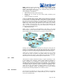
Potential applications within an IP Service Provider Network for the M-xxx are
explained below.
1.4.1
Backbone Routing
Juniper proposes using the M-xxx Internet backbone routers for interconnecting
the different sites in an IP Service Provider Network.
The advantage of using a high-speed backbone router for this purpose is that you
can use either E3/DS3 interfaces, ATM interfaces, which scale up to OC12
speeds today or Packet over SONET (POS) interfaces, which scale up to OC48.
Key features which make the M-xxx ideal for this role include:
Routing
§
Robust BGP4 implementation with confederations, route reflectors,
communities, route flap damping, TCP MD5 authentication and Multiprotocol
BGP. Junos can handle and scale for multiple EBGP and IBGP peering.
§
Highly scalable OSPF, IS-IS interior gateway protocols.
§
Flexible policy software for filtering and modifying route advertisements.
§
M-xxx is very responsive to routing fluctuation, remains stable even in the
face of massive routing churn, and experiences no impact on the forwarding
performance.
Port Density
§
M-xxx can support multiple interface types each in a very dense
configuration. This can offer considerable cost per port savings advantages.
All the interfaces can forward traffic at wire rate for any packet size and under
extremely unstable network conditions.
1.4.2
Peering
The M-xxx can also serve as an ideal peering router because of its robust,
feature-rich and interoperable BGP4 implementation and a flexible and powerful
routing policy software.
In many networks today, peering is done on an “edge” router. The M-xxx can
either serve this function by replacing the existing peering routers or you can do
peering on the core backbone routers.
For the connectivity to the different peers (ISPs), there is a wide range of options
that scale from DS3 to OC48 Sonet/SDH, each one offering high port density.
Multiple Juniper customers for the use on their own network have certified both
peering and backbone routing as ideal applications for the M-xxx.
1.4.3
Traffic Management via MPLS
Juniper Networks believes that Multiprotocol Label Switching (MPLS) is the
emerging solution to support traffic engineering in large service provider
networks.
It combines the advantages of router-based and ATM-based cores, while
eliminating the disadvantages. Juniper is able o
t fully support Service Providers’
plans to migrate to an MPLS based core backbone, from either an pure IP core or
a mixed IP / ATM core.
MPLS as a technology enables a services provider to :
1.5
§
Better engineer its own backbone to enforce quality of service, control the
traffic evolution and optimize costs,
§
Better serve its customers’ base with appropriate SLA’s, differentiated
qualities of service and new emerging services such as VPNs.
Active participation in standards bodies
Juniper is a member of the Optical Internetworking Forum. Juniper is also active
in the IETF (Internet Engineering Task Force), where Juniper employees have
contributed to a great number of RFC’s. Juniper is also active with organizations
such as NANOG (North American Network Operators Group), RIPE, APRICOT
and the MPLS Forum.
Page 9 /148
1.6
Juniper Networks Internet Backbone Routers Advantages
Features
Benefits
Architecture
Highly Integrated ASIC forwarding
§
§
§
§
§
§
Routing and forwarding performance cleanly
separated
§ Routing fluctuations and network instability do not impede packet
Fully sized and designed to perform lookups at a rate of 160 Mpps.
Scales well with large, complex forwarding tables.
Full utilization of expensive circuits.
Packet size does not affect forwarding performance.
Rock solid system stability.
Lower part count for high reliability.
forwarding at full wire rate.
§ Rapid convergence.
§ Reliable and predictable performance for latency sensitive traffic,
such as voice over IP and streaming video multicasting.
Single-stage buffering
§
§
§
§
Features are implemented in ASICs
§ Industry-leading performance with value-added services enabled
Redundant Switching and Forwarding Module
(SFM)
§ Increases system availability.
§ Ensures automatic failover to redundant SFM in case of failure.
Redundant Routing Engine and Miscellaneous
Control Subsystem (MCS)
§ Increases system availability.
§ Decreases mean time to repair (MTTR).
All components are hot swappable
§ Increases system serviceability and availability.
§ Decreases MTTR
JUNOS Internet software already deployed in the
largest and fastest growing networks
§ Proven performance and reliability.
Eliminates head-of-line blocking.
Efficiently uses available interface bandwidth.
Optimal support for multicast traffic.
Reduces latency by requiring only one write to and one read from
shared memory.
Interfaces
Market-leading port density
§ Efficient use of POP rack space.
§ Future growth not limited by space.
Fine granularity of interchangeable interfaces
§ Flexibly deployed in multiple environments including core, peering,
high-speed access, and hosting.
§ Lowers the cost of entry configurations.
Environmental
Maximum chassis power of 2,600 watts with
redundant, load sharing DC power supplies
§ Efficiently uses power for economical deployment and operation.
Protection Mechanisms
MPLS Fast Reroute
§ Recovers from MPLS path failures for SDH and WDM connections.
Dual-router Automatic Protection Switching (APS)
1:1
§ Ensures rapid recovery from router-to-ADM circuit failures by
Virtual Router Redundancy Protocol (VRRP)
§ Exploits the inherent redundancy of routers on a Gigabit Ethernet
switching to a back-up fiber.
LAN.
Page 10 /148
Features
Benefits
Performance -based IP Services
Performance-based packet filtering of inbound and
outbound traffic based on any combination of
matches
§ Source IP address
§ Destination IP address
§ DiffServ byte
§ IP protocol
§ IP fragmentation offset and control fields
(Offset, MF, DF)
§ Source transport port
§ Destination transport port
§ TCP control bits (SYN, ACK, FIN)
You can configure one input filter and one output
filter for each logical interface. You can set multiple
match conditions per filter, as well as configure
multiple actions for each match condition.
§ Maintains predictable performance with filtering enabled.
§ Increases the integrity of source addresses, and therefore reduces
Performance-based packet sampling
§ Statistical sampling at a configurable rate
§ Sampled data is stored locally on 6.4-GB
Routing Engine hard disk drive
§ Maintains predictable performance with sampling enabled.
§ High degree of fine granularity when used in conjunction with
the exposure to source-spoofing attacks.
§ Subscriber protection via outbound destination filters.
§ Traffic accounting via filter categorization and counters.
filtering.
§ Provides visibility into traffic type for online analysis (for example,
applications and histograms of packet sizes).
§ Helps with capacity planning and network design.
§ Customizable raw data archive of sampled headers for off-line
analysis. You can use this information for AS-to-AS and prefix-toprefix analysis.
Deterministic per-packet load balancing for load
sharing across multiple circuits
§ Maintains predictable performance with load balancing enabled.
§ Improved load sharing across parallel equal-cost paths in the
network.
§ Packet ordering within each TCP flow enables optimal throughput.
Support for Label Distribution Protocol (LDP) IETF
draft (draft-ietf-mpls-ldp-05.txt) and support for
optional features
§ Upstream unsolicited label distribution
discipline
§ Liberal label retention mode
§ Neighbor discovery
§ Provides interoperability with access devices that use LDP (for
example, tunneling of virtual private network traffic).
§ Supports a core IP network that does not carry full Internet routes
and where traffic engineering is not required.
Class of Service
Token bucket mechanism on SONET/SDH
interfaces
§ Enables you to perform rate policing on input.
Four queues per physical interface
§ Enables you to classify all out-bound traffic into four distinct groups.
Classification based on incoming logical interface,
IP precedence value, or destination IP address
§ Provides preferential traffic handling.
Weighted Round Robin queue servicing based on
configurable weights
§ Enables you to assign a percentage of bandwidth to each class.
§ Controls the amount of bandwidth each class receives on a circuit,
Random Early Detection congestion management
Configurable memory allocated to each queue
§
thereby ensuring that heavy traffic demands of some classes do not
adversely affect other classes.
Provides preferential traffic handling.
§
§
§
§
§
Reduces the probability that congestion will occur.
Minimizes packet loss and delay.
Maximizes TCP throughput.
Maximizes the utilization of links over time.
Provides preferential traffic handling
§ Gives more control over minimizing latency and the potential for
congestion by configuring the amount of available bandwidth.
Page 11 /148
2. THE JUNIPER NETWORKS INTERNET BACKBONE ROUTER PLATFORMS
2.1
The M20, M40 and M160 Internet Core Backbone Routers
The Juniper Networks’ M20T M , M40T M and M160T M Internet Core Backbone
Routers are designed to provide wire-speed forwarding rates across multiple
optical interfaces for all packet sizes. The M20 and M40 are intended to fill
multiple roles in large enterprises, ISP and carrier super-POPs, playing the role of
high speed access, aggregation, cross-connect, and core backbone device. To
do so, the M20T M , M40T M and M160T M have both best-of-class port density for
concentrating access devices, and backbone capacity for very high-speed
Internet cores. The forwarding engine includes Internet scale routing
implementations built by acknowledged experts in these protocols.
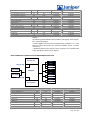
The M20T M , M40T M and M160T M architecture consists of a routing engine (RE), a
packet-forwarding engine (PFE), and various I/O cards. The RE maintains the
routing table and routing code, including SNMP functionality. The PFE is
dedicated solely to the forwarding of packets in the fastest way possible. This
separation ensures that high levels of route instability do not impact the
performance of the PFE and likewise, extremely high volumes of traffic do not
impact the ability of the RE to maintain peer relationships and calculate routing
tables.
A key distinction of the PFE hardware is the development of several customized
ASICs that form a complete system of buffer management, switching, route
lookup, and encapsulation. The design provides maximum stability in extraneous
operating conditions, while at the same time providing a much lower part count,
power consumption, and higher MTBF than conventional router or switch
designs.
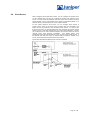
The M160 Internet Backbone Router
The M160 is Juniper Network’s evolution platform to provide higher density
STM-16 solutions and STM-64 based core networks. The M160 offers 4
times the capacity (160Gbps) and throughput of the M40.
The main features are as follows:
§
Continued use of JUNOS software, with proven features and reliability
for real Internet traffic.
§
Continuation of wirespeed philosophy, line rate forwarding regardless of
packet size
§
Increased STM-16 port densities, 32 per chassis, 64 per 7’ rack.
§
Support for OC192c cards, 8 per chassis.
§
Support for STM-4 & STM-1 POS/ ATM, Gigabit Ethernet.
§
Redundancy of power, routing engine, switch fabric module, system
clock module with automatic failover.
§
Chassis is just 35” high, i.e. half a rack, with 8 FPC/ 32 PIC slots.
Note - The drive to connect to OC192c trunks will depend very much on the
implementation of STM-64 capable WDMs in the transport layer.
The lowest port speed will be STM-1. It will be possible to re-utilize STM-4 &
STM-1 POS/ ATM and Gigabit PICs from M40 in the M160. The STM-16 and
STM-64 cards for the M160 are new implementations, for example, the new
STM-16 card takes up only one PIC slot in the M160.
Target Market
The M160 Internet Router is targeted at the largest Service Providers
needing increased OC -48 density over the M40 and a product path to OC192.
Page 12 /148
General Description
The M160 represents the next generation platform for Juniper Networks.
Building on the M40 product the M160 provides:
§
High Density OC-48c interfaces (up to 32 ports per system)
§
OC-192c interfaces to provide a higher interface speed and to provide
high speed optical connections to WDMs (available Q2 2000)
§
The ability to build a system with no single point of failure.
§
Enhance installation and servicability.
Design
The M160 leverages the proven M40 design by scaling the number of
switching cores in the system. The M40 consists of a single switching core
providing over 40Mpps of forwarding. The M160 is composed of up to 4
interconnected switching cores providing over 160Mpps of forwarding
performance.
Because the switching cores are oversized this design also provides
outstanding system resiliency. The failure of a switch fabric leaves sufficient
bandwidth to continue packet forwarding without system degradation.
To further improve resiliency the Routing Engines, which are responsible for
Layer 3 topology acquisition, are also redundant. Because of the system’s
distributed architecture this duplication allows for virtually uninterrupted
forwarding even if the primary Routing Engine fails. This duplication also
greatly simplifies routine system maintenance by allowing for the removal of
a Routing Engine while forwarding continues.
In addition to resiliency the Routing Engines also provide high performance.
Running JUNOS, a custom software system designed for the Internet, on
333Mhz Pentium processors the Routing Engines have the power to handle
control functions and traffic engineering at the Internet core.
Leveraging the larger switching core and the improved Routing Engines, the
M160 provides 4 times the interface density of the M40. Up to 32 OC-48c
interfaces or 8 OC-192c interfaces are supported in a single chassis. With
the small size and low power consumption of the M160 this allows up to 64
OC-48c or 16 OC-192c interfaces to be provisioned in a single 7 -foot rack.
Page 13 /148
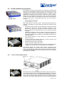
2.2
The M20 Hardware System
The M20 Internet Backbone Router provides high-speed interfaces for large
networks and network applications, such as those supported by Internet
backbone service providers. Application-specific integrated circuits (ASICs), a
definitive part of the router design, enable the router to achieve data forwarding
rates that match current fiber-optic capacity.
The router accommodates up to four Flexible PIC Concentrators (FPCs), each of
which can be configured with a variety of network media types—all together
providing up to 64 physical interface ports per system. The router architecture
cleanly separates control operations from packet forwarding operations. This
design eliminates processing and traffic bottlenecks, permitting the router to
achieve full line-rate performance. Control operations in the router are performed
by the Routing Engine, which runs JUNOS Internet software to handle routing
protocols, traffic engineering, policy, policing, monitoring, and configuration
management. Forwarding operations in the router are performed by the Packet
Forwarding Engine, which consists of hardware, including ASICs, designed by
Juniper Networks. The router’s maximum aggregate throughput is 20 Gbps. The
router can forward traffic at line rate for any combination of Physical Interface
Cards (PICs) that does not exceed 3 Gbps on a single FPC. Any combination that
exceeds 3 Gbps is supported, but constitutes oversubscription.
The router is a modular, rack-mountable system. It is 14 in. (36 cm.) high, 19 in.
(48 cm.) wide, and 21 in. (54 cm.) deep. Its size allows up to five routers to be
installed in one standard, 78-inch-high Telco rack. A fully populated router weighs
approximately 134 lbs. (61 kg).
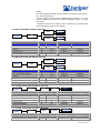
Component Replaceability
Most of the major router hardware components are field-replaceable. Fieldreplaceable components fall into two categories:
§
§
Hot-removable and hot-insertable—You can remove and replace these
components without powering down the system and disrupting routing
functions. Power supplies, fan assemblies, and Flexible PIC
Concentrators (FPCs) are hot-removable and hot-insertable.
Hot-pluggable—You can remove and replace these components without
powering down the system, but the system either stops forwarding
packets or switches to a warm shutdown mode as long as the
component is removed. The System and Switch Board (SSB) and the
Routing Engine are hot-pluggable.
Component Redundancy
The router is designed so that no single point of failure can cause the entire
system to fail. The following major hardware modules are redundant:
§
§
Routing Engine and SSB—If there is a Routing Engine or SSB failure,
the redundant Routing Engine or SSB immediately assumes routing
functions.
Power supplies —The router has two power supplies, which share the
load evenly. If one of the power supplies fails, the second power supply
can supply full power to the router’s components.
Page 14 /148
§
Cooling system —The cooling subsys tems have redundant components,
which are controlled by the SSB. If a fan fails, the remaining fans
provide sufficient cooling for the unit indefinitely.
Chassis
The router chassis is a rigid sheet metal structure that houses all the other router
hardware components. The chassis is 14 in. (36 cm) high, 19 in. (48 cm) wide,
and 21 in. (54 cm) deep. The chassis has a mounting system that installs into
standard 19-in. equipment racks or Telco center-mounted racks and allows
multiple routers to be installed into one standard, 78-in.-high rack.
The chassis contains the following components:
§
§
§
§
Two electrostatic discharge points (banana plug receptacles), one front
and one rear
Front-mounting metal ears on either side, used to bolt the chassis to the
rack
Optional 19-in. rack-mounting ears for Telco center-rack mounting
Optional front-mounting brackets
Routing Engine
The Routing Engine consists of an Intel-based PCI platform running JUNOS
Internet software. The Routing Engine module is located in the rear of the router
chassis, above the power supplies. It is housed in a metal case that is equipped
with thumbscrews to facilitate installation into and removal from the chassis. For
redundancy, you can have two Routing Engines in the router. If one Routing
Engine fails, the other one assumes the routing functions.
The Routing Engine is hot-pluggable. The Routing Engine LEDs are located on
the craft interface on the front of the router and are repeated on the Routing
Engine panel, which is part of the rear fan tray and is immediately to the right of
the Routing Engine. The Routing Engine module is a two-board subsystem
comprising the following components:
§
§
§
§
§
§
§
§
333-MHz mobile Pentium II processor with a 512-KB cache CPU.
SDRAM—Three 168-pin DIMM sockets capable of holding up to 768 MB
of ECC SDRAM memory.
Management access—One 10/100 Mbps Ethernet port (with
autosensing RJ-45 connector) and two RS-232 (DB-9 connector)
asynchronous serial ports, one for the console and one auxiliary. These
ports are on the router’s craft interface.
80-MB compact flash drive—Provides primary storage. It can hold two
software images, two configuration files, and microcode. This disk is
fixed and not accessible from the outside of the router.
6.4-GB IDE hard disk drive—Provides secondary storage for logs,
recording entire memory dumps, and rebooting the system in event of a
flash disk failure.
Compact flash disk drive —Provides tertiary storage. It is accessible from
the outside of the router. You can use one type of PC card, a Sandisk
110-MB PCMCIA PC card.
EEPROM—Contains serial numbers, review level.
Hardware timer—Used for internal clocking.
Packet Forwarding Engine
The Packet Forwarding Engine (PFE) provides Layer 2 and Layer 3 packet
switching, route lookups, and packet forwarding. The Packet Forwarding Engine
uses application-specific integrated circuits (ASICs) to perform these functions.
ASICs include the Distributed Buffer Manager, I/O Manager, Internet Processor,
and various media-specific controllers. The Packet Forwarding Engine occupies
the upper center front portion of the chassis and consists of four components:
§
§
§
Midplane—A single midplane forms the back of the FPC card cage. The
System and Switch Board (SSB) and up to four FPCs install horizontally
into the midplane from the front of the chassis.
SSB—The SSB installs horizontally into the midplane.
FPCs—Up to four FPCs can be installed into the midplane, below the
SSB. Each FPC has a set of connectors for attaching one or more PICs.
Page 15 /148
§
PICs—One to four PICs can be attached to each FPC. PICs provide
support for various network media, including OC-12 ATM, OC-48
SONET, Gigabit Ethernet, and DS3.
Midplane
The router midplane forms the back of the card cage. The FPCs, SSB, and craft
interface install into the midplane from the front of the chassis. Fan trays plug into
the midplane from both the front and rear of the chassis. Power supplies and the
Routing Engine plug into the midplane from the back of the chassis. The
midplane is a component of the Packet Forwarding Engine. It is responsible for
power distribution and signal connectivity. The router power supplies are
connected to the midplane, which distributes power and provides signal
connectivity to all the FPCs, the SSB, and other system components.
System and Switch Board (SSB)
The SSB occupies the top slot of the card cage, installing into the midplane from
the front of the chassis. The SSB houses the Internet Processor ASIC and two
Distributed Buffer Manager ASICs. The SSB communicates with the Routing
Engine using a dedicated 100-Mbps Fast Ethernet link that transfers routing table
data from the Routing Engine to the forwarding table in the Internet Processor
ASIC. The link is also used to transfer from the SSB to the Routing Engine
routing link-state updates and other packets destined for the router that have
been received through the router interfaces.
The SSB is a component of the Packet Forwarding Engine and performs the
following major functions:
§
§
§
§
§
§
Management of shared memory on the FPCs —The Distributed Buffer
Manager ASIC on the SSB uniformly allocates incoming data packets
throughout shared memory on the FPCs.
Transfer of outgoing data cells to the FPCs—A second Distributed
Buffer Manager ASIC on the SSB passes data cells to the FPCs for
packet reassembly when the data is ready to be transmitted.
Route lookups —The Internet Processor ASIC on the SSB performs
route lookups using the forwarding table stored in the synchronous
SRAM (SSRAM). After performing the lookup, the Internet Processor
ASIC informs the midplane of the forwarding decision, and the midplane
forwards the decision on to the appropriate outgoing interface.
Monitoring system components —The SSB monitors other system
components for failure and alarm conditions. It collects statistics from all
sensors in the system and relays them to the Routing Engine, which
sets the appropriate alarm. For example, if a temperature sensor
exceeds the first internally defined threshold, the Routing Engine issues
a “high temp” alarm. If the sensor exceeds the second threshold, the
Routing Engine initiates a system shutdown.
Transferring exception and control packets—The Internet Processor
ASIC passes exception packets to a microprocessor on the SSB, which
processes almost all of them. The remainder are sent to the Routing
Engine for further processing. Any errors originating in the Packet
Forwarding Engine and detected by the SSB are sent to the Routing
Engine using syslog messages.
Controlling FPC resets—The SSB monitors the operation of the FPCs. If
it detects errors in an FPC, the SSB attempts to reset the FPC. After
three unsuccessful resets, the SSB takes the FPC offline and informs
the Routing Engine. Other FPCs are unaffected, and normal system
operation continues.
The SSB is hot-insertable and hot-removable. You can remove and replace the
SSB without powering down the router, but doing so interrupts packet fowarding.
SSB Components
The SSB contains the following components:
§
Processing components
o 200-MHz CPU and supporting logic
o Internet Processor ASIC
o Distributed Buffer Manager ASICs
Page 16 /148
§
§
o 33-MHz PCI bus—Connects system ASICs
Storage components
o Four slots of 1-MB RAM for forwarding tables associated with
ASICs
o 64-MB DRAM for the microkernel
o EEPROM containing the SSB’s serial number and board
release version
o 512-KB boot flash EPROM (programmable on the board)
System interfaces
o Three LEDs
o 100-Mbps Fast Ethernet link for internal interface to the Routing
Engine and FPC boards
o RS-232 debugging port (DB-25 connector)
o 19.44-MHz reference clock (stratum 3) for SONET PICs
o I2C controller to read the I2C/EEPROMs in memory, the FPCs,
the midplane, and the power supplies
SSB LEDs
The SSB has two groups of LEDs, online/offline LEDs and status LEDs. The
online/offline LEDs indicate whether the SSB is online or offline. The status LEDs
indicate what type of task the SSB is performing.
Flexible PIC Concentrators (FPCs)
FPCs are the boards that hold the various media-specific PICs used in the router.
Up to four PICs can be installed on each FPC. FPCs install horizontally into the
midplane from the front of the chassis below the SSB. Any FPC can be installed
into any FPC slot. The FPCs are numbered 0 through 3, and the PFC slots are
labeled from top to bottom—FPC0, FPC1, FPC2, and FPC3. The FPCs connect
the PICs to the rest of the router so that incoming packets can be forwarded
across the midplane to the appropriate destination port. FPCs contain shared
memory, which is managed by the Distributed Buffer Manager ASIC on the SSB,
for storing data packets received by the PICs. The I/O Manager ASIC on each
FPC breaks incoming data packets from the PICs into 64-byte memory blocks,
which are stored in a shared memory buffer. It then reassembles them into data
packets when they are ready for transmission.
FPCs are hot-insertable and hot-removable. When you remove an FPC and
install a new one, the midplane flushes the entire system memory pool before the
new card is brought online, a process that takes about 200 ms. When you install
an FPC into a running system, the Routing Engine downloads the FPC software,
the FPC runs its diagnostics, and the PICs on the FPC slot are enabled. No
interruption occurs to the routing functions. If a slot is not occupied by an FPC, a
blank FPC carrier must be installed to shield the empty slot so that cooling air can
circulate properly throughout the FPC card cage.
FPC Components
§
§
§
§
§
§
Each FPC contains the following components:
FPC board carrier that has a PowerPC 603e processor and an I/O
Manager ASIC
Two identical 64-MB SDRAM DIMMs —Used as shared memory by the
Distributed Buffer Manager ASIC on the SSB
1-MB SSRAM module
8-MB DRAM—Used by the PowerPC 603e processor
EEPROM—Contains the FPC’s serial number and board release version
FPC LEDs
Each FPC has two LEDs that report its status. The LEDs are located on the craft
interface.
Physical Interface Cards (PICs)
Up to four PICs can be installed into slots on each FPC. PICs provide the
physical connection to various network media types. PICs receive incoming
packets from the network and transmit outgoing packets to the network. During
this process, each PIC performs framing and line-speed signaling for its media
Page 17 /148
type. Before transmitting outgoing data packets, the PICs encapsulate the
packets received from the FPCs. Each PIC is equipped with a media-specific
ASIC that performs control functions tailored to the PIC’s media type.
PICs are field-replaceable. To remove a PIC, you first remove its host FPC, which
is hot-removable and hot-insertable.
PIC LEDs
Each port on each PIC has one LED, located on the PIC faceplate above the
transceiver. Each LED has four different states. If the FPC that houses the PIC
detects a PIC failure, the FPC informs the SSB, which in turn sends an alarm to
the Routing Engine.
Craft Interface
The craft interface allows you to view normal status and troubleshooting
information at a glance and to perform many system control functions. The craft
interface is located below the SSB on the front of the chassis and contains the
following elements :
§
§
§
§
§
§
§
Alarm Relay Contacts, Alarm LEDs, and Alarm Cutoff Button
Routing Engine Ports
Link and Activity Status Lights
Routing Engine LEDs
Routing Engine LEDs and Buttons
FPC LEDs
Routing Engine Ports
The power supply LEDs are located on the power supply faceplates, at the
bottom rear of the chassis, not on the craft interface.
Alarm Relay Contacts, Alarm LEDs, and Alarm Cutoff Button
The craft interface contains two sets of alarm relay contacts, which are on the left
side of the craft interface. The upper set is activated by a system red alarm and
the lower set by a system yellow alarm. Immediately to the right of the alarm
relay contacts are the red and yellow alarm LEDs. These LEDs light when a red
or yellow alarm condition occurs. To the right of the LEDs is the alarm
cutoff/lamp test (ACO/LT) button. Press this button to deactivate the red or yellow
alarm LED. Note that deactivating the LED and alarm does not correct the
problem. You also use the ACO/LT button to test all the LEDs on the craft
interface.
Routing Engine Ports
The Routing Engine has three ports for connecting external management
devices. You can use the command-line interface (CLI) on these management
devices to configure the router. These ports are located at the lower right corner
of the craft interface:
§
§
§
§
Console port—Used to connect a system console to the Routing Engine
with an RS-232 s erial cable.
Auxiliary port—Used to connect a laptop or modem to the Routing
Engine with an
RS-232 serial cable.
Ethernet management port—Used to connect the Routing Engine to a
management LAN (or any other device that plugs into an Ethernet
connection) for out-of-band management of the router system. The
Ethernet port can be 10 or 100 Mbps and uses an autosensing RJ-45
connector.
Link and Activity Status Lights
The link status lights are located to the left of the Ethernet management ports on
the craft interface, and the activity status lights are located to the right of the
Ethernet management ports on the craft interface. The link and activity status
lights report the status of the external management connections. The link light
indicates whether the link has been established and the status light indicates data
is being transferred.
Routing Engine LEDs
Page 18 /148
The Routing Engine LEDs on the craft interface report the status of the Routing
Engine. They are located above and below the Juniper Networks logo near the
middle of the craft interface.
Routing Engine Offline Buttons
Routing Engine offline buttons are used to take the Routing Engine offline in case
the Routing Engine needs to be replaced. The offline buttons are located to the
right of the Routing Engine. The Routing Engine LEDs are repeated on the
Routing Engine panel, which is located to the right of the Routing Engine on the
back of the chassis.
FPC LEDs
The FPC LEDs on the craft interface report the status of each FPC. They are
located on the right side the craft interface. Table 6 describes the FPC LEDs.
FPC Offline Buttons
FPC offline buttons are used to take the FPC offline if it needs to be replaced.
The offline buttons are located on the right side of the craft.
Power Supplies
The power supplies install at the lower rear of the chassis, in the power supply
bays. The power supplies are internally connected to the midplane, which
distributes the different output voltages produced by the power supplies
throughout the system and its components. The router has two fully redundant
power supplies that load-share during normal operation. A single power supply
can provide full power (up to 750 W) for as long as the system is operational.
Redundancy is necessary only in case of power supply failure. Each power
supply has an internal fan and is self-cooled.
Power supplies are field-replaceable. They are hot-removable and hot-insertable,
but you must turn off the power to the individual supply before removing it from
the chassis. When the power is cut off to one power supply or a failure occurs
within a power supply, the other power supply immediately and automatically
assumes the entire electrical load.
The router supports and AC power supplies. An enable control signal on the
output connector ensures that the power supply is fully seated into the router
midplane before the power supply can be turned on. The enable pin prevents a
user-accessible energy hazard, so there is no interlocking mechanism. The
enable pin disables the voltage at the output connector if the power supply is not
turned off before removal. Each power supply has status LEDs located below the
handle near the middle of the supply.
Cooling System
The router cooling system consists of the following components:
§
§
§
Three front fan trays —Cool the FPCs and the SSB. These fan trays are
located on the left front side of the chassis.
One rear fan tray—Cools the Routing Engine. This fan tray is located
immediately to the right of the Routing Engine
Power supply integrated fan—A built-in fan cools each power supply.
The four fan trays work together to provide side to side cooling. The fan trays
plug directly into the router midplane. Each front fan tray is a single fieldreplaceable unit that contains three fans. The rear fan tray is a field-replaceable
unit that contains two fans. Both front and rear fan trays are hot-swappable.
Page 19 /148
2.3
The M40 Hardware System
The M40 Internet Backbone Router provides high-speed interfaces for large
networks and network applications, such as those supported by Internet
backbone service providers. Application-specific integrated circuits (ASICs), a
definitive part of the router design, enable the router to achieve data forwarding
rates that match current fiber-optic capacity.
The router accommodates up to eight Flexible PIC Concentrators (FPCs), each of
which can be configured with a variety of network media types—all together
providing up to 128 physical interface ports per system.
The router architecture cleanly separates control operations from packet
forwarding operations. This design eliminates processing and traffic bottlenecks,
permitting the router to achieve full line-rate performance. Control operations in
the router are performed by the Routing Engine, which runs JUNOS Internet
software to handle routing protocols, traffic engineering, policy, monitoring,
policing, and configuration management. Forwarding operations in the router are
performed by the Packet Forwarding Engine, which consists of hardware,
including ASICs, designed by Juniper Networks.
The router’s maximum aggregate throughput is 40 Gbps. The router can forward
traffic at line rate for any combination of Physical Interface Cards (PICs) that does
not exceed 3 Gbps on a single FPC. Any combination that exceeds 3 Gbps is
supported, but constitutes oversubscription.
The router is a modular, rack-mountable system. The chassis is 35 in. high, 19 in.
wide, and 23.5 in. deep (91 cm high, 48 cm wide, and 60 cm deep). The chassis
mounting system installs into standard 19-in. equipment racks or Telco centermounted racks and allows two routers to be installed into one standard, 78-in.
rack. A fully populated router weighs approximately 250 lbs. (90 kg).
Component Replaceability
Most of the major router hardware components are field-replaceable. Fieldreplaceable components fall into two categories:
§
§
Hot-removable and hot-insertable—You can remove and replace these
components without powering down the system and disrupting routing
functions. Power supplies, fan assemblies, and Flexible PIC
Concentrators (FPCs) are hot-removable and hot-insertable.
Hot-pluggable—You can remove and replace these components without
powering down the system, but the system either stops forwarding
packets or switches to a warm shutdown mode as long as the
component is removed. The System Control Board (SCB) and the
Routing Engine are hot-pluggable.
Page 20 /148
Component Redundancy
The router is designed so that no single point of failure can cause the entire
system to fail. The following major hardware modules are redundant:
§
§
§
Host module—Comprises a Routing Engine and SCB functioning
together. The router can have one or two host modules.
Power supplies —The router has two power supplies, which share the
load evenly. If one of the power supplies fails, the second power supply
can supply full power to the router’s components.
Cooling system —The front and rear cooling subsystems have redundant
components, which are controlled by the SCB. If an impeller or fan fails,
the SCB increases the speed of the remaining impellers and fans to
provide sufficient cooling for the unit indefinitely.
Chassis
The router chassis is a rigid sheet metal structure that houses all the other router
hardware components. The chassis is 35 in. (89 cm) high, 19 in. (38 cm) wide,
and 23.5 in. (60 cm) deep. The chassis mounting system installs into standard
19-in. equipment racks or Telco center-mounted racks and allows two routers to
be installed into one standard, 78-in. rack.
The chassis contains the following components:
§
§
§
§
Two electrostatic discharge points (banana plug receptacles), one front
and one rear
Front-mounting metal ears on either side, used to bolt the chassis to the
rack
19” rack-mounting ears for Telco center rack mounting.
Front-mounting ears have protectors when the chassis is center
mounted.
Routing Engine
The Routing Engine consists of JUNOS Internet software running on an Intelbased PCI platform. The Routing Engine is located in the rear of the M40 router
chassis. The Routing Engine module is housed in a metal case that is equipped
with handles to facilitate installation and removal from the chassis. The Routing
Engine module installs into the rear of the M40 router chassis, in a compartment
behind the card cage.
The Routing Engine is field-replaceable and hot-pluggable. The Routing Engine
consists of the following hardw are components:
§
§
§
System processors
o Motherboard, with a Pentium processor that runs the JUNOS
software.
o Ethernet board for internal communication between the Routing
Engine and the Packet Forwarding Engine.
Storage components
o 256-MB DRAM—Provides storage for the routing and
forwarding tables.
o 80-MB flash disk—Provides primary storage for router software
images. It can hold two images, two configurations files, and
microcode.
o 6.4-GB IDE hard disk—Provides secondary storage for
rebooting the system in the event of a flash disk failure, as well
as providing storage for memory dumps.
o 120-MB LS-120 drive—Provides alternate secondary storage.
The same shape and size as the standard 1.44-MB 3.5-inch
diskette, the LS-120 disk holds 120 MB of data and can be
used for installing software images and configurations.
System interfaces
o 100-Mbps internal connection to the M40 router System Control
Board—Connects the Routing Engine to the Packet Forwarding
Engine.
Page 21 /148
o
o
o
o
Two asynchronous serial ports on the craft interface—Connect
a console, laptop, or modem for direct or local area network
management access to the M40 router.
Ethernet port (10 or 100 Mbps, with an autosensing RJ-45
connector) on the craft interface—Connects the Routing Engine
to a terminal server or an SNMP management station for outof-band management of the M40 router.
System LEDs on the craft interface—Green LEDs indicate OK
status and red LEDs indicate Fail status.
LCD screen on the craft interface—Displays system status and
alarm information.
Packet Forwarding En gine
The Packet Forwarding Engine provides Layer 2 and Layer 3 packet switching,
route lookups, and packet forwarding. The Packet Forwarding Engine uses
application-specific integrated circuits (ASICs) to perform these functions. ASICs
include the Distributed Buffer Manager, I/O Manager, Internet Processor, and
various media-specific controllers. The Packet Forwarding Engine occupies the
upper center front portion of the FPC card cage and consists of four components:
§
§
§
§
Backplane—A single backplane forms the rear of the FPC card cage.
The System Control Board (SCB) and up to eight Flexible PIC
Concentrators (FPCs) install vertically into the backplane from the front
of the chassis.
System Control Board (SCB)—The SCB installs vertically into the middle
slot of the backplane.
Flexible PIC Concentrators (FPCs)—Up to eight FPCs can be installed
into the backplane, four on either side of the SCB. Each FPC has a set
of connectors for attaching one or more Physical Interface Cards (PICs).
Physical Interface Cards (PICs)—One to four PICs can be attached to
each FPC. PICs provide support for various network media, such as
OC-12 ATM, OC-48 SONET, Ethernet, and DS3.
Backplane
The router backplane forms the back of the FPC card cage. The SCB and all the
FPCs install into the backplane from the front of the chassis. The backplane
contains a temperature sensor and is cooled by three fans operating in unison.
The backplane is a component of the Packet Forwarding Engine and performs
three major functions:
§
§
§
Power distribution and signal connectivity—The router power supplies
are connected to the backplane, which distributes power and provides
signal connectivity to all the FPCs, the SCB, and other system
components.
Management of shared memory on the FPCs —The Distributed Buffer
Manager ASIC on the backplane uniformly allocates incoming data
packets throughout shared memory on the FPCs.
Transfer of outgoing data cells to the FPCs—A second Distributed
Buffer Manager ASIC on the backplane passes data cells to the FPCs
for packet reassembly when the data is ready to be transmitted.
System Control Board (SCB)
The System Control Board (SCB) occupies the center slot of the card cage,
installing into the backplane from the front of the chassis. The SCB is a
component of the Packet Forwarding Engine and performs four major functions:
§
§
Route lookups —The Internet Processor ASIC on the SCB performs
route lookups using the forwarding table stored in the synchronous
SRAM (SSRAM). After performing the lookup, the Internet Processor
informs the backplane of the forwarding decision, and the backplane
forwards the decision on to the appropriate outgoing interface.
Monitoring of system components —The SCB monitors other system
components for failure and alarm conditions. It collects statistics from all
sensors in the system and relays them to the Routing Engine, which
sets the appropriate alarm. For example, if a temperature sensor
exceeds the first internally defined threshold, the Routing Engine issues
Page 22 /148
§
§
a “high temp” alarm. If the sensor exceeds the second threshold, the
Routing Engine initiates a system shutdown.
Transfer of exception and control packets—The Internet Processor ASIC
on the SCB passes exception packets to a microprocessor on the SCB,
which processes almost all of them. The remainder are sent to the
Routing Engine for further processing. Any errors originating in the
Packet Forwarding Engine and detected by the SCB are sent to the
Routing Engine using SYSLOG messages.
Control of FPC resets—The SCB monitors the operation of the FPCs. If
it detects errors in an FPC, the SCB attempts to reset the FPC. After
three unsuccessful resets, the SCB takes the FPC offline and informs
the Routing Engine. Other FPCs are unaffected, and normal system
operation continues.
SCB Components
The SCB contains the following components:
§
§
§
Processing components
o PowerPC603e processor running at 200 MHz for handling
exception packets
o Internet Processor ASIC, which performs route lookups
o 33-MHz PCI bus, which connects the PowerPC603e processor
and the Internet Processor
Storage components
o Four slots of 1-MB to 4-MB SSRAM for the forwarding tables
that are associated with the ASICs
o 64-MB DRAM for the microkernel
o EEPROM containing the SCB’s serial number and board
release version
o 512-KB boot flash EPROM (programmable on the board)
System interfaces
o Two pai rs of L EDs
o 100-Mbps internal interface to the Routing Engine
o 8-bit parallel interface to the craft interface
o 9-port, 10-Mbps Ethernet internal hub interface to the FPC
boards (control path)
o RS-232 debugging port (DB-25 connector)
o 19.44-MHz reference clock (stratum 3) for SONET PICs
o I2C controller to read the I2C/EEPROMs in memory, FPCs,
backplane, and power supplies
SCB LEDs
Two pairs of circular LEDs are located on the front edge of the SCB.
Flexible PIC Concentrators (FPCs)
Flexible PIC Concentrators (FPCs) are the boards that hold the various mediaspecific PICs used in the router. Up to eight FPCs install vertically into the
backplane from the front of the chassis, four on either side of the SCB. Any FPC
can be installed into any FPC slot. Each FPC has four connectors into which a
Physical Interface Card (PIC) can be installed, yielding up to four PICs per FPC.
The FPCs connect the PICs to the rest of the router so incoming packets can be
forwarded across the backplane to the appropriate destination port. FPCs contain
shared memory, which is managed by the Distributed Buffer Manager ASIC on
the backplane, for storing data packets received by the PICs. The I/O Manager
ASIC on each FPC breaks incoming data packets from the PICs into 64-byte
memory blocks, which are stored in a shared memory buffer. It then reassembles
them into data packets when they are ready for transmission.
FPCs are hot-insertable and hot-removable. Each FPC is mounted on a card
carrier. When you remove an FPC and install a new one, the backplane flushes
the entire system memory pool before the new card is brought online, a process
that takes about 200 ms. When you install an FPC into a running system, the
Page 23 /148
Routing Engine downloads the FPC software, the FPC runs its diagnostics, and
the PICs on the FPC slot are enabled. Routing functions continue uninterrupted.
FPC Components
Each FPC contains the following components:
§
§
§
§
§
FPC board carrier with a PowerPC 603e processor and an I/O Manager
ASIC
Two identical 64-MB SDRAM DIMMs, used as shared memory by the
Distributed Buffer Manager ASIC on the backplane
1-MB SSRAM
8-MB DRAM, used by the 603e processor
EEPROM containing the FPC’s serial number and board release version
FPC LEDs
Each FPC has two LEDs that report its status. The LEDs are located below each
FPC, on the craft interface.
Physical Interface Cards (PICs)
PICs provide the physical connection to various network media types. Up to four
PICs can be installed into slots on each FPC. PICs receive incoming packets
from the network and transmit outgoing packets to the network. During this
process, each PIC performs framing and line-speed signaling for its media type.
Before transmitting outgoing data packets, the PICs encapsulate the packets
received from the FPCs. Each PIC is equipped with a media-specific ASIC that
performs control functions tailored to the PIC’s media type.
PICs are field-replaceable. To remove a PIC, you first remove its host FPC, which
is hot-removable and hot-insertable.
PIC LEDs
Each port on each PIC has one LED, located on the PIC faceplate above the
transceiver. Each LED has four different states, which are described in Table 3. If
the FPC that houses the PIC detects a PIC failure, the FPC informs the SCB,
which in turn sends an alarm to the Routing Engine.
Craft Interface
The craft interface allows you to view status and troubleshooting information at a
glance and to perform many system control functions. Located on the lower
impeller tray on the front of the chassis, the craft interface contains the following
elements :
§
§
§
§
System LEDs and Buttons
LCD Screen
Alarm Relay Contacts
Routing Engine Ports
System LEDs and Buttons
The system LEDs on the craft interface report the status of the Routing Engine,
the status of each FPC, and general system alarm conditions. The system
buttons on the craft interface allow you to reset clocks or stop alarms. The
following system LEDs and buttons are located on the craft interface :
§
§
§
FPC LEDs—Two LEDs (one green OK and one red Fail) indicate the
status of each FPC. The two LEDs and an offline button are located
below each FPC module slot.
Alarm LEDs—One large red Alarm LED and one large amber Alarm
LED indicate two levels of alarm conditions. You use the alarm cutoff
button to turn off either alarm.
Routing Engine LEDs —A red Fail LED and a green OK LED indicate the
status of the Routing Engine.
LCD Screen
The craft interface has a four-line LCD screen that operates in one of two display
modes:
§
Idle mode—Default mode that displays the current system status.
Page 24 /148
§
Alarm mode—Displays alarm conditions whenever the red or yellow
alarm LED is lit.
Alarm Relay Contacts
The craft interface contains two sets of relay contacts for alarms. You can cable
the alarm relay contacts to an external alarm device. Whenever a system
condition triggers either the red or yellow alarm on the craft interface, the alarm
relay contacts also are activated.
Routing Engine Ports
The Routing Engine has three ports for connecting external management
devices. You can use the command-line interface (CLI) on these management
devices to configure the router. These ports are located at the lower right corner
of the craft interface:
§
§
§
Console port—Used to connect a system console to the Routing Engine
with an RS-232 serial cable.
Auxiliary port—Used to connect a laptop or modem to the Routing
Engine with an RS-232 serial cable.
Ethernet management port—Used to connect the Routing Engine to a
management LAN (or any other device that plugs into an Ethernet
connection) for out-of-band management of the M40 router system. The
Ethernet port can be 10 or 100 Mbps and uses an autosensing RJ-45
connector.
Power Supplies
There are two fully redundant power supplies. A single power supply can provide
full power (up to 1500 watts) for as long as the system is operational.
Redundency is necessary only in case of power supply failure. At the instant that
power is cut off to one power supply, the other power supply automatically
assumes the entire electrical load. Each power supply has a system ground
connector.
The power supplies install at the lower rear of the chassis, in the power supply
bays. The power supplies are internally connected to the backplane, which
distributes the different output voltages produced by the power supplies
throughout the system and its components, depending on their voltage
requirements. Each power supply contains an integrated fan that cools the power
assembly. The complete power supply is field-replaceable.
The router supports two types of modular power supplies, AC and DC. Both types
are field-replaceable and hot-removable and hot-insertable. Each power supply
has a handle for removing the unit from the power supply bay. Both types have a
safety interlock lever that prevents the unit from being removed until the power is
cut off.
Power Supply LEDs
Two LEDs on each power supply faceplate report power supply status. In
addition, a fail condition triggers the red alarm LED on the craft interface. Table 7
describes the power supply LEDs.
Cooling System
The M40 router cooling system consists of three separate subsystems :
§
§
§
Impellers —Two pairs of redundant impellers cool the Packet Forwarding
Engine.
Triple Fan Assemblies —Three load-sharing fans cool the backplane and
the Routing Engine.
Power Supply Integrated Fan—A built-in fan cools each power supply.
Each cooling subsystem maintains a separate air flow, and each is monitored
independently for temperature control.
An air filter at the lower front of the chassis covers all three air intakes.
Impellers
The router is equipped with two redundant pairs of impellers to cool the Packet
Forwarding Engine components (that is, the backplane, SCB, FPCs, and PICs).
As the impellers draw air into the front of the card cage through an air filter that
covers the air intake vent, they force the exhaust from the rear of the chassis
Page 25 /148
through vents located in the upper impeller tray. The air is channelled past the
Packet Forwarding Engine components, keeping them cool.
During normal operation, both pairs of impellers function at less than full capacity.
A temperature sensor on the backplane controls the speed of the impellers. If you
remove one impeller tray, the temperature of the backplane increases and the
speed of the remaining pair of impellers adjusts automatically to keep the
temperature within the acceptable range.
Impeller trays are field-replaceable, hot-insertable, and hot-removable. The upper
and lower impeller trays are not interchangeable.
Triple Fan Assemblies
Three fan assemblies cool the Routing Engine and backplane. The fan
assemblies are located above the Routing Engine near the upper rear of the
chassis. They operate in unison to maintain an acceptable operating temperature
for the Routing Engine and backplane. The fans blow air out the exhaust vent at
the rear of the chassis, drawing air in through an air filter that covers the air intake
vent. The air is channeled past the rear of the backplane and around the Routing
Engine.
The fans are load-sharing. If one fan is removed or fails, the other two fans can
assume the full load. The backplane temperature sensor detects temperatures
above the acceptable range. Fan failure or an excessive temperature condition
triggers alarm LEDs on the craft interface and activates alarm relay contacts.
Each fan is field-replaceable, hot-insertable, and hot-removable.
Power Supply Integrated Fan
Each power supply has its own integrated fan, which is used exclusively to cool
the power supply. The fan blows air out the exhaust vent at the rear of the
chassis, drawing air in through an air filter that covers the air intake vent at the
front of the chassis.
Page 26 /148
2.4
The M160 Hardware System
The M160 Internet Backbone Router is a complete routing system that provides
SDH/SONET, ATM, Gigabit Ethernet, and other high-speed interfaces for large
networks and network applications, such as those supported by Internet service
providers (ISPs). Application-specific integrated circuits (ASICs), a definitive part
of the router system design, enable the router to achieve data forwarding rates
that match current fiber-optic capacity. The router accommodates up to eight
Flexible PIC Concentrators (FPCs), which can each be configured with a variety
of network media types—altogether providing up to 32 OC-12, 32 OC-48, or 8
OC-192 ports per system.
The router’s maximum aggregate throughput is 160 Gbps. The router can forward
traffic at line rate for any combination of PICs that does not exceed 12.8 Gbps on
a single FPC. Any combination exceeding 12.8 Gbps is supported, but constitutes
oversubscription. The router architecture cleanly separates control operations
from packet forwarding operations. This design eliminates processing and traffic
bottlenecks, permitting the router to achieve full line-rate performance. Control
operations in the router are performed by the Routing Engine, which runs JUNOS
Internet software to handle routing protocols, traffic engineering, policy, policing,
monitoring, and configuration management. Forwarding operations in the router
are performed by the Packet Forwarding Engine, which consists of hardware,
including ASICs, designed by Juniper Networks.
The router is a modular, rack-mountable system. Its size allows two routers to be
installed in one standard, 78-in.-high Telco rack.
Component Replaceability
The router’s major hardware components are field replaceable, including:
§
§
§
§
§
§
§
§
§
§
§
§
§
Switching and Forwarding Modules (SFMs)
Flexible PIC Concentrators (FPCs)
Physical Interface Cards (PICs)
PFE Clock Generators (PCGs)
Routing Engine
Miscellaneous Control Subsystem (MCS)
Front impeller assembly with craft interface
Rear upper impeller assembly
Rear lower impeller assembly
Fan tray with cable management system
Connector Interface Panel (CIP)
Power supplies
Air filter
There are two types of field-replaceable components:
Page 27 /148
§
§
Hot-insertable and hot-removable—You can remove and replace these
components without powering down the router or disrupting the routing
functions. The power supplies, SFMs, PICs and FPCs are hot-insertable
and hot-removable.
Hot-pluggable—You can remove and replace these components without
powering down the router, but the routing functions of the system are
interrupted when the component is removed. The PCGs, the MCS, and
the Routing Engine are hot-pluggable.
Component Redundancy
The router is designed so that no single point of failure can cause the entire
system to fail.
Routing Engines
The following major hardware modules are redundant:
SFM
§
MCS
PCG
MCS
SFM
§
Power Suplies
§
§
§
SFMs —The router can have up to four interconnected SFMs. If one
SFM fails, the switching and forwarding functions of the failed module
are distributed among the remaining SFMs. Total bandwidth is reduced
by 1/n, where n is the total number of SFMs installed in the router. For
example, in a system with four SFMs, each SFM handles 25 percent of
the forwarding capacity.
PCGs—The router has two PCGs. Both PCGs send their clock signals
to the forwarding components, along with a signal that indicates which
clock is the master. If one PCG fails, the other PCG becomes the master
system clock.
Host module—Comprises a Routing Engine and MCS functioning
together. The router can have one or two host modules. If two host
modules are installed, one functions as the master and the other as
backup. If the master host module (or either of its components) fails, the
backup takes over as the master host module. To operate, each host
module requires a Routing Engine and MC S to be installed in adjacent
slots.
Power supplies —The router has two power supplies, which share the
load evenly. If one of the power supplies fails, the second power supply
can supply full power to the router’s components indefinitely.
Cooling system —The front and rear cooling subsystems have redundant
components, which are controlled by the MCS. If an impeller or fan fails,
the MCS increases the speed of the remaining impellers and fans to
provide sufficient cooling for the unit indefinitely.
Chassis
The router chassis is a rigid sheet metal structure that houses all the router
hardware components. The chassis is 35 in. (89 cm) high, 17.5 in. (44.4 cm)
wide, and 29 in. (73 cm) deep. At its widest point—the front support posts—the
router is 19.2 in. (48.8 cm) wide. It is 19 in. (48.3 cm) wide to the tips of the center
rack-mounting ears. The chassis installs into standard 19 in. equipment racks or
Telco center-mounted racks, and two routers can be installed into one standard,
78-in. rack.
The chassis includes the following components:
§
§
§
§
Two front support posts used to bolt the chassis to a front-mounting rack
Two 19” rack-mounting ears for center rack mounting
Two electrostatic discharge (ESD) points (banana plug receptacles), one
front and one rear
Two internally threaded inserts providing grounding points for the router.
Packet Forwarding Engine
The Packet Forwarding Engine (PFE) provides Layer 2 and Layer 3 packet
switching, route lookups, and packet forwarding. The Packet Forwarding Engine
uses application-specific integrated circuits (ASICs) to perform these functions.
ASICs include the Distributed Buffer Manager, I/O Manager, Internet Processor II,
Packet Director, and various media-specific controllers.
The Packet Forwarding Engine consists of the follow ing components:
§
Midplane—A single, passive midplane is located in the center of the
chassis. The FPCs install vertically into the midplane from the front of
Page 28 /148
§
§
§
§
the chassis, and the SFMs, Routing Engine, MCS, and PCGs install
horizontally from the rear of the chassis.
Switching and Forwarding Modules (SFMs)—From one to four SFMs
can be installed into the rear of the chassis.
Flexible PIC Concentrators (FPCs)—From one to eight FPCs can be
installed into the front of the chassis. Each FPC has a set of connectors
for attaching one or more PICs. The router supports two types of FPCs:
o FPC1—Supports lower-speed SONET OC-12 and Gigabit
Ethernet PICs
o FPC2—Supports higher-speed OC-48 and Tunnel PICs
Physical Interface Cards (PICs)—From one to four PICs can be installed
in each FPC. PICs provide support for various network media, including
OC-12 ATM, OC-12, OC-48 and OC-192 SDH/SONET, Channelized
OC-12, and Gigabit Ethernet.
PFE Clock Generators (PCGs)—Two PCGs are installed into the rear of
the chassis.
Midplane
The midplane is located in the center of the chassis and forms the rear of the
FPC card cage. The FPCs install into the midplane from the front of the chassis,
and the SFMs, Routing Engines, MCSs, and PCGs install into the midplane from
the rear of the chassis. The power supplies and cooling system components also
connect to the midplane. The midplane contains an EEPROM that stores the
serial number and revision level of the midplane.
The midplane performs the following major functions:
§
§
§
Transfer of data—Data packets are transferred across the midplane
from the FPCs to the SFMs, which perform their switching and
forwarding function, then transfer the packets back across the midplane
to the shared memory buffers on the FPCs.
Power distribution—The router power supplies are connected to the
midplane, which distributes power to all the router’s components.
Signal connectivity—The midplane provides signal connectivity to the
FPCs, SFMs, Routing Engines, and other system components for
monitoring and control of the system.
Switching and Forwarding Modules (SFMs)
The Switching and Forwarding Modules (SFMs) provide route lookup, filtering,
and switching to the destination FPC. Up to four interconnected SFMs can be
installed in the router, providing a total of 160 million packets per second (Mpps)
of forwarding. The SFMs provide the following functions:
§
§
§
§
Route lookups —The Internet Processor II ASIC on each SFM performs
route lookups using the forwarding table stored in the synchronous
SRAM (SSRAM).
Management of shared memory on the FPCs—One Distributed Buffer
Manager ASIC on each SFM uniformly allocates incoming data packets
throughout shared memory on the FPCs.
Transfer of outgoing data packets to the FPCs—A second Distributed
Buffer Manager ASIC on each SFM passes data packets to the FPCs for
reassembly when the data is ready to be transmitted.
Transfer of exception and control packets—The Internet Processor II
ASIC passes exception packets to the microprocessor on the SFM,
which processes almost all of them. The remainder are sent to the
Routing Engine for further processing. Any errors originating in the
Packet Forwarding Engine and detected by the SFMs are sent to the
Routing Engine using syslog messages.
The SFMs are hot-removable and hot-insertable. Inserting or removing an SFM
causes a brief interruption in forwarding performance (about 500 ms) as the
Packet Forwarding Engine reconfigures the distribution of packets across the
remaining SFMs.
SFM Components
The SFM is a two-board system comprising the following components:
Page 29 /148
§
§
§
§
§
§
§
Two Distributed Buffer Manager ASICs—One sends packets to the
output buffer and oneforwards notification to the I/O Manager ASICs on
the FPCs.
Internet Processor II ASIC—Performs route lookups.
8-MB of parity-protected SSRAM.
Processor subsystem —Comprises one PowerPC603e processor, 256KB of parity-protected Level 2 cache, and 64-MB of parity-protected
DRAM. This subsystem handles exception packets and management of
the SFM.
EEPROM—Stores the serial number and revision level.
Two L EDs—One Green OK and one amber FAI L.
Offline button for module removal.
SFM LEDs
Each SFM has two LEDs that indicate its status.
Flexible PIC Concentrators (FPCs)
The Flexible PIC Concentrators (FPCs) house the various PICs used in the
router. Up to eight FPCs install vertically into the midplane from the front of the
chassis. The FPCs are numbered left to right, from FPC0 to FPC7. Each FPC
has four connectors into which a PIC can be installed, allowing up to four PICs
per FPC. An FPC can be installed into any FPC slot, regardless of the PICs it
contains. If a slot is not occupied by an FPC, a blank FPC panel must be installed
to shield the empty slot and to allow cooling air to circulate properly through the
FPC card cage.
The FPCs connect the PICs to the rest of the router so that incoming packets can
be forwarded across the midplane to the appropriate destination port. FPCs
contain shared memory, which is managed by the Distributed Buffer Manager
ASIC on each SFM, for storing data packets received by the PICs. The I/O
Manager ASIC on each FPC divides incoming data packets from the PICs into
64-byte memory blocks, which are stored in a shared memory buffer, and
reassembles them into data packets when they are ready for transmission.
FPCs are hot-insertable and hot-removable. Removing an FPC causes a brief
interruption of forwarding performance (about 200 ms) as the Packet Forwarding
Engine flushes the memory pool.
When you install an FPC into an operating router, the Routing Engine downloads
the FPC software, the FPC runs its diagnostics, and the PICs on the FPC slot are
enabled. No interruption occurs to the routing functions.
FPC Components
Each FPC contains the following components:
§
§
§
§
§
§
§
§
§
FPC card carrier—Contains the ASICs, connectors, and processor
subsystem.
Four I/O Manager ASICs—Parse Layer 2 and 3 data and perform
encapsulation and segmentation.
Two Packet Director ASICs—One distributes incoming packets to the
I/O Manager ASICs and the second directs outgoing packets from the
I/O Manager ASIC to the PICs.
Eight identical 32-MB SDRAM DIMMs —Form the shared memory buffer
for the system.
1-MB parity-protected SSRAM—Stores data structures used by the I/O
Manager ASICs.
Processor subsystem —Comprises one PowerPC 603e-based CPU with
32 MB of parity-protected DRAM.
EEPROM—Stores the serial number and revision level of the FPC.
Two LEDs—One Green OK and one red FAI L, which are located on the
craft interface.
Offline button for module removal, located on the craft interface.
FPC LEDs
Each FPC has two LEDs that report its status. The LEDs are located above each
FPC, on thecraft interface.
Page 30 /148
FPC1 and FPC2
The router supports two types of FPC:
§
§
FPC1—Supports single-port OC-12 and Gigabit Ethernet PICs.
FPC2—Supports higher-speed OC-48 and Tunnel PICs.
The router can operate with any combination of FPC1s and FPC2s installed.
The installation and removal of the two FPC types is identical. PICs that can be
inserted on an FPC2 are distinguished by having an offline button on their
faceplate. The FPC1 has built-in offline buttons for the PICs it holds. In this
document, both the FPC1 and FPC2 are referred to simply as “FPC” except
where the differences between the two are being discussed.
Physical Interface Cards (PICs)
You can install up to four Physical Interface Cards (PICs) into slots on each FPC.
PICs provide the physical connection to various network media types. PICs
receive incoming packets from the network and transmit outgoing packets to the
network. During this process, each PIC performs framing and line-speed
signaling for its media type. Before transmitting outgoing data packets, the PICs
encapsulate the packets received from the FPCs. Each PIC is equipped with an
ASIC that performs control functions specific to the PIC’s media type.
PICs are hot-removable and hot-insertable.
PIC LEDs
Each port on each PIC has one LED, located on the PIC faceplate below the
optical transceiver. The Tunnel PIC, which has no ports, has a single LED. Each
LED has four different states.
PIC Offline Buttons
Each PIC has an offline button used for hot-removing the PIC from an operating
router. The SDH/SONET OC-48 and Tunnel PICs that insert into an FPC2 each
have an offline button on their faceplates. For the SDH/SONET OC-12, ATM OC12, and Gigabit Ethernet PICs that insert into an FPC1, the offline button is on the
FPC1 card carrier.
PIC Media Types
PICs for the M160 router support the following network media types:
§
§
§
§
§
ATM OC-1 2
Channelized OC-12
Gigabit Ethernet
SDH/SONET OC-12, OC-48 and OC-192
Tunnel
You can install ATM OC-12, channelized OC-12, Gigabit Ethernet, or SONET
OC-12 PICs on a single FPC in any of the four PIC slots. For example, you can
install an OC-12 SONET PIC, an OC-12 ATM PIC, a Gigabit Ethernet PIC, and a
channelized OC-12 PIC on the same FPC.
The FPC1 can accommodate an aggregate throughput of up to OC-48 (3.2
Gbps). The FPC2 can accommodate an aggregate throughput of up to OC-192
(12.8 Gbps). The SONET OC-192 PIC is a "quad-wide" interface card that
occupies an entire FPC slot. You can install a SONET OC-192 PIC into any FPC
slot.
The number of ports on each PIC and the number of PICs that can be installed in
a single FPC depend on the network media type (PIC interface) and the FPC
type.
PFE Clock Generators (PCGs)
The router has two PFE Clock Generators (PCGs). They are located in the rear of
the chassis to the right of the Routing Engine slots. The PCGs supply the 125MHz system clock to the modules and ASICs making up the Packet Forwarding
Engine. The PCGs both send clock signals to the Packet Forwarding Engine
modules, along with a signal indicating which is the master clock source. The
master Routing Engine controls which PCG is master and which is backup.
The PCGs are field-replaceable and hot-pluggable.
PCG Components
Page 31 /148
Each PCG contains the following components:
§
§
§
§
125-MHz system clock generator
EEPROM—Stores the serial number and revision level of the PCG
Three LEDs—one blue MASTER, one green OK and one amber FAI L
Offline button for module removal
PCG LEDs
Three LEDs are located on the faceplate of the PCG. Table 6 describes the
functions of these LEDs.
Host Module
The host module provides the routing and system management functions of the
router. Additionally, the host module provides the SONET clock source for
SONET interfaces. The host module consists of the following components :
§
§
Routing Engine
Miscellaneous Control Subsystem (MCS)
The router can be equipped with one or two host modules. For each host module,
the Routing Engine and MCS function as a unit, each component requiring the
other to operate; if the adjacent component is not present, a Routing Engine or
MCS will not operate, even if physically installed in the router.
Routing Engine
The Routing Engine consists of an Intel-based PCI platform running JUNOS
Internet software. The Routing Engine maintains the routing tables used by the
router and controls the routing protocols that run on the router. The Routing
Engine installs into the center rear of the chassis. The Routing Engine is hotpluggable.
The router can be equipped with up to two Routing Engines for redundancy. If
two Routing Engines are installed, one acts as the master Routing Engine and
the other acts as backup. If the master Routing Engine fails or is removed, the
backup restarts and becomes the master Routing Engine.
Each Routing Engine requires an MCS to be installed in an adjacent slot. RE0
installs below MCS0, and RE1 installs above MCS1. Even if a Routing Engine is
physically installed in the chassis, it does not function if no MCS is present in the
adjacent slot.
Routing Engine Components
The Routing Engine is a two-board system comprising the following components:
§
§
§
§
§
§
§
§
§
CPU—One 333-MHz mobile Pentium II processor with an integrated
256-KB Level 2 cache.
SDRAM—Three 168-pin DIMMs containing 768-MB ECC SDRAM,
which provides storage for the routing and forwarding tables and for
other Routing Engine processes.
80- or 96-MB compact flash disk—Provides primary storage. It can hold
two software images, two configurations files, and microcode. This disk
is fixed and is not accessible from outside the router.
6.4-GB IDE hard disk—Provides secondary storage for log files, memory
dumps, and rebooting the system in the event of a flash disk failure.
110 MB PC card —Provides storage for software images for system
upgrades.
Out-of-band management access—One 10/100 Mbps Ethernet port
(with autosensing RJ-45 connector), and two RS-232 (DB9 connectors)
asynchronous serial ports, one console and one auxiliary, to connect to
a console, laptop or terminal server. The management access ports are
located on the CIP.
EEPROM—Stores the serial number of the Routing Engine.
Three LEDs—One green MASTER, one green ONLINE and one red
OFFLINE, which are located on the craft interface.
Reset button—On the Routing Engine faceplate.
Miscellaneous Control Subsystem (MCS)
Page 32 /148
The MCS works with the Routing Engine to provide control and monitoring
functions for router components and to provide SONET clocking for the router.
The MCS installs into the midplane from the rear of the chassis.
The router can be equipped with up to two MCSs for redundancy. If two MCSs
are installed, one acts as the master MCS and the other acts as backup. If the
master MCS fails or is removed, the backup restarts and becomes the master
MCS.
Each MCS requires a Routing Engine to be installed in an adjacent slot. MCS0
installs above RE0, and MCS1 installs below RE1. Even if an MCS is physically
installed in the chassis, it does not function if no Routing Engine is present in the
adjacent slot.
The MCS performs the following functions:
§
§
§
§
§
Monitoring and control of router components—Monitors components for
failure and alarm conditions. The MCS collects statistics from all sensors
in the system and relays them to the Routing Engine, which generates
control messages or sets an alarm. The MCS relays control messages
from the Routing Engine to the router components.
Power-up and power-down of components —Controls the power-up
sequence of router components at startup, and powers down
components when their offline buttons are pressed.
Control of mastership—In a system with redundant Routing Engine,
MCS, or PCG modules, the MCS signals which of the modules is the
master and which is the backup.
Control of FPC resets—If the MCS detects errors in an FPC, it attempts
to reset the FPC. After three unsuccessful resets, the MCS takes the
FPC offline and informs the Routing Engine. Other FPCs are unaffected,
and normal system operation continues.
SONET clock source—The MCS generates the 19.44-MHz SONET
clock. Each MCS supplies the SONET clock signal, along with a signal
that indicates which MCS is the master SONET clock. Each MCS also
provides two BITS interfaces for synchronization of the SONET clocks to
an external reference source.
The MCS also monitors the SONET clock, the SONET reference clocks (from the
FPCs and the BITS interfaces) and the system clocks from the PCGs.
MCS Components
The MCS contains the following components:
§
§
§
§
§
§
§
§
PCI interface to the Routing Engine
100-Mbps Ethernet switch for inter-module communication
19.44-MHz stratum 3 reference clock for SONET PICs
Two BITS interfaces for external clock reference
I 2 C controller to monitor the status of router components
RS-232 debugging port
Three LEDs—One blue MASTER, one green OK, and one amber FAI L
Offline button for module removal
MCS LEDs
Three LEDs are located on the faceplate of the MCS.
Craft Interface
The craft interface allows you to view status and troubleshooting information at a
glance and to perform many system control functions. The craft interface is
located on the front of the chassis above the FPC card cage and contains the
following elements :
§
§
§
§
Alarm LEDs and Alarm Cutoff Button
LCD Display and Navigation Buttons
Host Module LEDs
FPC LEDs and Offline Button
Connector Interface Panel (CIP)
Page 33 /148
The Connector Interface Panel (CIP) is located at the left side of the FPC card
cage. The CIP consists of connectors for the Routing Engines, Building
Integrated Timing Source (BITS) interfaces for the MCS, and alarm relay
contacts.
Routing Engine Ports
The CIP has two sets of ports for connecting the Routing Engines to external
management devices. You can use the command-line interface on these
management devices to configure the router.
The upper set of ports, marked HOST0, connects to the Routing Engine in the
RE0 slot, and the lower set, marked HOST1, connects to the Routing Engine in
the RE1 slot. Each set includes the following ports :
§
§
§
Console port—Used to connect a system console to a Routing Engine
with an RS-232 serial cable.
Auxiliary port—Used to connect a laptop or modem to a Routing Engine
with an RS-232 serial cable.
Ethernet management port—Used to connect a Routing Engine to a
management LAN (or any other device that plugs into an Ethernet
connection) for out-of-band management of the router. The Ethernet port
can be 10 or 100 Mbps and uses an autosensing RJ-45 connector.
The Ethernet management port has two LEDs, which indicate the type of
connection in use. A yellow LED lights when a 10-Mbps connection is in use, and
a green LED lights when a 100-Mbps connection is in use.
BITS Interfaces
The CIP has a pair of Building Integrated Timing Source (BITS) interfaces for
connecting the router to external clock sources. The BITS A interface connects to
HOST0 and the BITS B interface connects to HOST1. These interfaces are
located below the Routing Engine management ports.
Alarm Relay Contacts
The CIP has two sets of relay contacts for connecting the router to external alarm
devices. Whenever a system condition triggers either the red or yellow alarm on
the craft interface, the alarm relay contacts also are activated. The alarm relay
contacts are located below the BITS interfaces.
Power Supplies
The router has two load-sharing DC power supplies. The power supplies are
located at the lower rear of the chassis, below the rear lower impeller and the
circuit breaker box. The power supplies are internally connected to the midplane,
which delivers the power input from the circuit breaker box and distributes the
different output voltages produced by the power supplies to the router’s
components, depending on their voltage requirements.
The power supplies are fully redundant. If one power supply fails or is removed,
the second power supply instantly assumes the entire electrical load. A single
power supply can provide full power (up to 2600 W) for as long as the system is
operational. Redundancy is necessary only in case of power supply failure.
The router supports DC power supplies only. Power supplies are hot-removable
and hot-insertable. Each power supply has handles to facilitate removal from the
chassis.
The power supplies are cooled by air drawn through the chassis by the cooling
system components.
Power Supply LEDs
Four LEDs on each power supply faceplate indicate the power supply’s status. In
addition, a fail condition triggers the red alarm LED on the craft interface.
Power Supply Self-Test Button
Below the power supply LEDs is a self-test button that is used to test the power
supply. Only qualified service personnel should use the self-test button.
Cooling System
The router’s cooling system consists of two separate subsystems:
Page 34 /148
§
§
Front Cooling Subsystem—An upper impeller and a lower fan tray cool
the FPCs, the PICs and the midplane.
Rear Cooling Subsystem —A pair of impellers cools the SFMs, the host
module, the PCGs, and the power supplies.
The MCS monitors the temperature of the router’s components. When the router
is operating normally, the impellers and fans function at lower than full speed. If
an impeller or fan fails or is removed, the temperature increases and the speed of
the remaining impellers and fans is automatically adjusted to keep the
temperature within the acceptable range.
The air intake for both cooling subsystems is located on the front of the chassis,
below the FPC card cage. An air filter in front of the air intake prevents dust and
other particles from entering the cooling system.
Front Cooling Subsystem
The front cooling subsystem comprises a large, central impeller that is located
above the FPC card cage and a fan tray located below the FPC card cage.
Together, they cool the FPCs and PICs.
The front impeller and fan tray are both hot-insertable and hot-removable.
Rear Cooling Subsystem
The rear cooling subsystem comprises a pair of impellers that are located at the
upper right and lower left of the rear of the chassis. Together, they cool the
SFMs, Routing Engine, MCS, and PCGs.
Each rear impeller is hot-insertable and hot-removable. The upper and lower
impellers are not interchangeable. The power supplies are cooled by air drawn
through the chassis by the cooling system.
Air Filter
The air filter, located at the front of the air intake, prevents dust and other
particles from entering the cooling system. Behind the air filter is a non-removable
air intake cover which provides EMI shielding.
Page 35 /148
2.5
2.5.1
M20, M40 and M160 Internal Architecture
Internal Architecture of the M20 and M40
The M20 and M40 architecture consists of a Routing Engine (RE), a PacketForwarding Engine (PFE), and various I/O cards called PIC (Physical Interface
Cards) which are inserted on master interface modules called FPC (Flexible PIC
Concentrators) . The RE maintains the routing table and routing code, including
SNMP functionality. The PFE is dedicated solely to the forwarding of packets in
the fastest way possible. This separation ensures that high levels of route
instability do not impact the performance of the PFE and likewise, extremely high
volumes of traffic do not impact the ability of the RE to maintain peer relationships
and calculate routing tables.
Routing
Table
Distributed
Buffer
Manager
ASIC
Internet
Processor II
ASIC
Forwarding
Table
Forwarding
Table
Distributed
Buffer
Manager
ASIC
Routing
Engine
Packet
Forwarding
Engine
Shared Memory
I/O
Manager
ASIC
PIC
I/O
card
Packet IN
I/O
Manager
ASIC
Flexible PIC
Concentrator
PIC
I/O
card
Packet OUT
A key distinction of the M40 PFE (Packet Forwarding Engine ) is a set of Juniper
Networks-developed custom application-specific integrated circuits (ASICs) that
deliver a comprehensive hardware-based system for route lookups, buffer
management, switching, and encapsulation/decapsulation functions. To ensure a
non-blocking forwarding path, all channels between the ASICs are oversized,
dedicated paths.
The heart of the M40 PFE is the Internet Processor ASIC. The Internet
Processor supports a lookup rate of over 40 million packets per second (for a
routing table with 80,000 entries and more) to deliver true wire-speed forwarding
performance. With over one million gates, the Internet Processor is the largest
and fastest route lookup ASIC ever implemented on a router platform and
deployed in the Internet.
The Distributed Buffer Manager ASIC coordinates the M40 router's shared
memory system. The advantages of a shared-memory system include reduced
complexity, elimination of head-of-line blocking typically associated with multistage buffering systems, multicast forwarding, and efficient use of memory
bandwidth.
The I/O Manager ASIC supports wire-rate packet parsing, packet prioritizing, and
queuing disciplines. On SONET/SDH, ATM, and Gigabit Ethernet PICs,
customized ASICs perform the framing functions.
Thus to summarize, there are :
§
1 Internet Processor ASIC,
§
2 Distributed Buffer Manager ASICs
§
1 I/O Manager ASIC per FPC
§
1 Media specific ASIC (Sonet/ATM/Gigabit Ethernet) per PIC.
Page 36 /148
In addition to ASICs, there is a 200 MHz PowerPC 603e processor that manages
the link between the RE and PFE, manages forwarding table updates, manages
ASICs and environmental systems and controls craft interface.
The RE which is an Intel-based Compact PCI platform has a 233 Mhz Pentium
processor. Note that this is used only for routing functions only and not for packet
forwarding.
2.5.2
Differences between the M20 and the M40
The Routing Engines between the M20 and M40 differ in form factor, CPU (PII333 vs. Pentium 200), and memory (768 MB vs. 256 MB). The software and
functionality in the platform is exactly the same. On the packet forwarding engine
the M20 uses the SSB (System and Switch Board) while the M40 uses the SCB
(System Control Board). Both platforms share a common set of ASIC’s, and
layout and form factor changes have been made for size and architecture
(midplane vs. backplane) considerations, but the functionality remains exactly the
same. The Distributed buffer manager ASICs are located on the System and
Switch Board on the M20, while it is located on the midplane on the M40.
Logical View of the M20
Internet
Processor II
I/O
Mgr
PIC
PIC
PIC
PIC
PD
in
PIC
PD Shared
out RAM
FPC
I/O
Mgr
PIC
PIC
PIC
PD
in
PD Shared
out
RAM
FPC
SSB
I/O
Mgr
PIC
PIC
PIC
PIC
Distributed
Buffer Managers
PD
in
PIC
PD Shared
out
RAM
FPC
I/O
Mgr
PIC
PIC
PIC
PD
in
PD Shared
out
RAM
FPC
SSB : System & Switch Board
Logical View of the M40
Internet
Processor II
I/O
Mgr
PIC
PIC
PIC
PD
in
PD Shared
out
RAM
PIC
PIC
FPC
PIC
I/O
Mgr
PIC
PD
in
PD Shared
out RAM
I/O
Mgr
PIC
PIC
PIC
FPC
PIC
SCB
PD
in
PD Shared
out RAM
I/O
Mgr
PIC
PIC
PIC
FPC
PIC
Distributed
Buffer Managers
PD
in
PD Shared
out RAM
FPC
PIC
SCB : System Control Board
2.5.3
Internal Architecture of the M160
The two key components of the M160 architecture are the Packet Forwarding
Engine (PFE) and the Routing Engine, which are connected via a 100-Mbps link.
The PFE is responsible for packet forwarding performance. It consists of the
Flexible PIC Concentrators (FPCs), PICs, Switching and Forwarding Modules
(SFMs), and state-of-the-art ASICs.
Page 37 /148
The Routing Engine maintains the routing tables and controls the routing
protocols. It consists of an Intel-based PCI platform running JUNOS software.
Another key architectural component is the Miscellaneous Control Subsystem
(MCS), which provides SONET/SDH clocking and works with the Routing Engine
to provide control and monitoring functions.
The architecture ensures industry-leading service delivery by cleanly separating
the forwarding performance from the routing performance. This separation
ensures that stress experienced by one component does not adversely affect the
performance of the other since there is no overlap of required resources. Routing
fluctuations and network instability do not limit the forwarding of packets. The use
of ASICs ensures that the forwarding table maintains a steady state, which is
particularly beneficial during times of netw ork instability.
Internet
Processor II
PIC
PD
in
PD
out
SFM
Distributed
Buffer Managers
I/O
Mgr
I/O
Mgr
I/O
Mgr
I/O
Mgr
I/O
Mgr
I/O
Mgr
I/O
Mgr
I/O
Mgr
I/O
Mgr
PD
in
PD
out
I/O
Mgr
FPC
PD
in
I/O
Mgr
PD
out
I/O
Mgr
I/O
Mgr
PD
in
PD
out
I/O
Mgr
FPC
FPC
I/O
Mgr
I/O
Mgr
FPC
PIC
Leading-edge ASICs
The feature-rich M160 ASICs deliver a comprehensive hardware-based system
for route lookups, filtering, sampling, load balancing, buffer management,
switching, encapsulation, and de-encapsulation functions. To ensure a nonblocking forwarding path, all channels between the ASICs are oversized,
dedicated paths.
Internet Processor II ASICs
Each of the four Internet Processor II ASICs (one per SFM) support a lookup rate
of over 40 Mpps (for a routing table with 80,000 entries). With over one million
gates, the Internet Processor II ASIC delivers high-speed forwarding performance
with advanced services, such as filtering and sampling, enabled. It is the largest,
fastest, and most advanced ASIC ever implemented on a router platform and
deployed in the Internet.
Distributed Buffer Manager ASICs
The Distributed Buffer Manager ASICs allocate incoming data packets throughout
shared memory on the FPCs. This single-stage buffering improves performance
by requiring only one write to and one read from shared memory. There are no
extraneous steps of copying packets from input buffers to output buffers. The
shared memory is completely nonblocking, which in turn, prevents head-of-line
blocking.
Packet Director ASICs
The Packet Director ASICs balance and distribute packet loads across the four
I/O Manager ASICs per FPC. Since each SFM represents 40 Mpps of lookup and
40 Gbps of throughput, and since the Packet Director ASICs balance traffic
across the I/O Manager ASICs before it is forwarded to the SFM, the aggregate
throughput is 160 Gbps.
I/O Manager ASICs
The I/O Manager ASICs support wire-rate packet parsing, packet prioritizing, and
queuing. Each I/O Manager ASIC divides the packets, stores them in shared
memory (managed by the Distributed Buffer Manager), and re-assembles the
packets for transmission.
Page 38 /148
Media-specific ASICs
The media-specific ASICs perform physical layer functions, such as framing.
Each PIC is equipped with an ASIC or FPGA that performs control functions
tailored to the PIC's media type. SDH/SONET Manager ASIC
§
§
§
ATM Manager ASIC
DS-3 Manager FPGA
Gigabit Ethernet Manager ASIC
Packet Forwarding Engine
The PFE provides Layer 2 and Layer 3 packet switching, route lookups, and
packet forwarding. It forwards an aggregate of up to 160 Mpps for all packet sizes
under all network conditions. The aggregate throughput is over 160 Gbps simplex
or 80 Gbps full duplex with eight 12.8-Gbps FPCs installed.
The PFE supports the same ASIC-based features supported by the M20 and M40
routers. For example, class-of-service features include policing, classification,
priority queuing, Random Early Detection and Weighted Round Robin to increase
bandwidth efficiency. Filtering and sampling are also available for restricting
access, increasing security, and analyzing network traffic using the Internet
Processor II ASIC.
Finally, the PFE delivers maximum stability during exceptional conditions, while
also providing a significantly lower part count. This stability reduces power
consumption and increases mean time between failure.
Flexible PIC Concentrators
The FPCs house PICs and connect them to the rest of the router so that incoming
packets are then forwarded across the midplane to the appropriate destination
port. Each FPC slot contains an FPC1, FPC2, or an OC-192c/STM-64 PIC. There
are four dedicated 3.2-Gbps full-duplex channels (one per SFM) between each
M160 FPC slot and the core of the PFE.
Each FPC contains shared memory for storing data packets received; the
Distributed Buffer Manager ASICs on each SFM manage this memory. Each FPC
also contains two Packet Director ASICs for sending bytes to each of the four I/O
Manager ASICs, also located on the FPC.
Physical Interface Cards
PICs provide a complete range of fiber optic and electrical transmission interfaces
to the network. All PICs except the OC-192c/STM-64 occupy one of four PIC
spaces in an FPC (that is, they are single-wide). The OC-192c/STM-64 PIC
occupies an entire FPC slot.
The M160 router offers flexibility and conserves valuable rack space by
supporting the PICs and port densities described in the following table.
Additionally, it supports the Tunnel Services PIC, which enables the M160 router
to function as the ingress or egress point of an IP-IP unicast tunnel, a Cisco
generic routing encapsulation (GRE) tunnel, or a Protocol Independent Multicast Sparse Mode (PIM-SM) tunnel. The Tunnel Services PIC delivers OC-48/STM-16
bandwidth, but does not have a physical interface due to its loopback function
within the M160 chassis.
OC-192c/STM-64 PIC
The Juniper Networks OC-192c/STM-64 is the first 10-Gbps OC-192c/STM-64
interface on the market. Using the new SONET Manager II ASIC, this PIC yields
a full 10-Gbps throughput at wire rate for any packet size, under all network
conditions.
§
§
§
The OC-192c/STM-64 PIC combines the functions of a PIC and an FPC.
Like other PICs, it also provides the physical interface to the network.
Like the FPCs, it contains shared memory, two Packet Director ASICs,
and four I/O Manager ASICs. Additionally, the OC-192c/STM-64 PIC
resides in an FPC slot.
Switching and Forwarding Modules
The SFMs perform route lookup, filtering, and sampling, as well as provide
switching to the destination FPC. Hosting both the Internet Processor II ASIC and
two Distributed Buffer Manager ASICs, the SFM is responsible for making
forwarding decisions, distributing packets throughout memory, and forwarding
Page 39 /148
notification of outgoing packets. There are four SFMs, thus ensuring automatic
failover to a redundant SFM in case of failure.
Routing Engine
The Routing Engine maintains the routing tables and controls the routing
protocols, as well as the JUNOS software processes that control the router’s
interfaces, the chassis components, system management, and user access to the
router. These routing and software processes run on top of a kernel that interacts
with the PFE.
The Routing Engine processes all routing protocol updates from the network, so
PFE performance is not affected.
The Routing Engine implements each routing protocol w ith a complete set of
Internet features and provides full flexibility for advertising, filtering, and modifying
routes. Routing policies are set according to route parameters, such as prefixes,
prefix lengths, and BGP attributes.
You can install a redundant Routing Engine to ensure maximum system
availability and to minimize MTTR in case of failure. Each Routing Engine
requires an adjacent MCS.
2.5.4
Switching architecture
The M20/M40/M160 switch architecture is based on a shared memory fabric that
uses highly integrated ASICs to handle and forward packets as efficiently as
possible. The switch fabric is referred to as the Packet Forwarding Engine (PFE).
The PICs, FPCs, Backplane and System Control Board (SCB) form the PFE and
each plays an active role in packet forwarding.
Routing
Table
Distributed
Buffer
Manager
ASIC
Internet
Processor II
ASIC
Forwarding
Table
Forwarding
Table
Distributed
Buffer
Manager
ASIC
Shared Memory
I/O
Manager
ASIC
PIC
I/O
card
I/O
Manager
ASIC
PIC
I/O
card
The PFE consists of a set of Juniper-developed custom ASICs.
The
M20/M40/M160 PFE consists of a single-stage, shared memory system with a
central 40 Mpps ASIC lookup engine. Packets are written to and read from
memory only once, ensuring more efficient throughput.
Packet memory is
located on Flexible PIC Controller (FPC) cards so that as interfaces are added,
the required memory is also added. Single-stage buffering greatly reduces
complexities and throughput delays associated with multistage buffering systems.
The shared memory advantages are efficient utilization of buffer memory, no
head of line blocking, and a natural fit to multicast applications.
All paths between the ASICs in the PFE are oversized, dedicated channels.
Memory bandwidth and lookups are considerably oversized and the shared
memory approach eliminates the head of line blocking challenges of a crossbar
system. This is evidenced by the fact that the M40/M20 can handle sustained
bursts of minimum sized packets without packet loss.
The packet forwarding engine architecture for the M40 is explained below. The
M20 and M160 have the same architecture as the M40. For the description of the
switching architecture, the M40 is used as an example but the same
characteristics apply to the M20 and M160.
The function of the packet forwarding engine can be understood by following
the progress of a packet into a line card (FPC), through the switching fabric, and
then out of another line card for transmission to the next network element.
Packets arrive into the M20/M40/M160 system via a PIC interface on a FPC card.
Each packet is received and parsed by the media-specific ASIC on the PIC, and
then forwarded to the I/O Manager ASIC on the FPC. The I/O Manager ASIC
parses the Layer 2 headers, and examines the IP header length, time-to-live byte,
and IP header checksum before chopping the packets into 64-byte cells. These
cells are sized appropriately for efficient storage and retrieval from pooled
memory, and are unrelated to ATM cells.
The Distributed Buffer Manager (incoming) ASIC, directs the temporary storage
of the cells into a pooled memory (packet memory) provided collectively by all
available FPCs. The packet memory is considered as a single bank of memory
and is managed as a single resource by the Distributed Buffer Manager ASICs,
although it is actually located on each individual FPC. The Distributed Buffer
Manager (incoming) ASIC ensures an even distribution of cells across all FPCs.
The Distributed Buffer Manager (incoming) ASIC transmits the packet header
information gathered by the I/O Manager ASIC to the Internet Processor ASIC,
where a forwarding decision is made. The results of this decision are transmitted
to the relevant outgoing interface, and Distributed Buffer Manager (outgoing)
ASIC receives the relevant cells back from the pooled memory.
Page 40 /148
PD
Out
Buffer
Memory
The cells are then reassembled in the I/O Manager ASIC on the outgoing FPC
and passed to the chip on the PIC for encapsulation and transmission.
PIC
The pooled memory source is deliberately oversized, and is comprised of
memory provided by all available FPCs. The size of the memory pool ensures
that each cell is never held up waiting for available buffer memory, and therefore
the forwarding process is never unduly interrupted or delayed. Automatic
redundancy is provided, should a FPC’s memory fail, by virtue of the fact that the
memory is a pooled resource. No cell is held up waiting or tied to a specific FPC
before it can be processed.
PIC
Route lookups and forwarding instructions to output queues are handled by a
dedicated lookup engine. No routing control background process can interfere
with the forwarding process.
PIC
PD
In
I/O
Mgr
Physical
Interface
Card (PIC)
The outgoing cells are reassembled into a packet, for outbound transmission just
prior to transmission to the output port. The queuing discipline is implemented in
the I/O Manager ASIC as four packet pointer queues per physical port (e.g. each
OC-3 SONET port on a 4xOC-3 PIC would have its own set of queues). These
queues are serviced in a weighted round robin fashion. Queue selection is based
on parameters in the packet and the results of the forwarding decision.
Congestion control is implemented by a RED implementation, with three separate
drop profiles. The drop profile can be selected based on the transport layer
protocol or based on the traffic policing mechanisms on the input port.
2.5.5
The Routing Engine
M20
M40
M160
The Routing Engine (RE) is the component of the system that performs the
routing function. The RE is a PCI-based Pentium platform running a UNIX-like
operating system optimized to support a large number of interfaces and large
routing and forwarding tables. The RE is connected to the Packet Forwarding
Engine (PFE) through a 100-Mbps channel.
The RE constructs the PFE’s
forwarding table. The PFE’s forwarding table is what is used to forward all
packets transiting through the router. The RE constructs the forwarding table
based on information from several sources: addresses of local interfaces, static
routing configuration and dynamic routing and signaling protocols. Junos has an
idea of a preference for a prefix. The preference is the value used in calculating
the forwarding table when candidate paths for that prefix are found in multiple
routing protocols. Some protocols, such as BGP, allow the preference to be
configured per-prefix while other protocols, such as IS-IS, are configured with a
preference value to apply to all routes.
In an environment where a M20/M40/M160 is configured to exchange routing
information through dynamic protocols such as BGP and IS-IS, routing messages
that arrive on the PFE’s interfaces must be sent up to the RE. A packet
containing a routing message for the local system is received just like all other
packets. Specifically, the packet is received and immediately buffered. In
parallel with the buffering, a route lookup is done. It is at the route-lookup stage
where the processing differs between transit packets and packets for local
delivery. At this stage, the route lookup engine sees that the packet is for local
delivery, so it retrieves the entire packet from packet buffers and sends it across
the 100-Mbps channel to the RE. Once the packet arrives at the RE, the routing
software can process the message and make whatever appropriate changes,
additions or deletions to its forwarding table. Finally, any changes to the
forwarding table made on the RE are flushed to the PFE’s forwarding table.
Routing tables exist only in the memory of the RE. There is one primary routing
table, although the data structure used allows it to hold routes from multiple
routing protocols and neighbors. An unlimited number of additional routing tables
can be created by the user through software configuration. There are two
primary uses for multiple routing tables. First is to support different routing
policies for unicast and multicast. Second is to support the MPLS requirement of
mapping an IP prefix to a label. Although this feature only has two uses currently,
it affords flexibility for the future. The size of the routing tables is limited only by
the amount of memory in the RE, which is 256 MB on the M40, and 768 MB on
the M20 and M160. The maximum number of routes that can be stored is
impossible to state in an absolute sense because it depends on the configuration
of the box (for example, number of active routing protocols, number of neighbors,
rate of route flap, complexity of routing policies and number of unique prefixes
versus duplicates). A conservative maximum is a few hundred thousand prefixes
– on the order of 300,000.
Page 41 /148
Forwarding tables exist in the RE and in the PFE. In the RE, forwarding tables
are present at both the routing software and operating system levels. The routing
software must be aware of the forwarding table because the routing software is
the element of the system that chooses which routes are selected for use. The
routing software tells the operating system what its forwarding table should be.
Finally, the PFE’s forwarding table is created by flushing the operating system’s
forwarding table into the PFE. The RE supports very large forwarding tables
given that a forwarding table can be represented more concisely than a routing
table. The forwarding table in the PFE is stored in 4 MB or 8 MB of specialpurpose memory on the System Control Board (SCB) on the M40, and System
and Switching Board (SSB) on the M20, and on each of the 4 Switching Fabric
Modules (SFM) on the M160.
The system is built such that the 256/768 MB of memory in the RE and the 4/8
MB of special-purpose memory on the SCB/SSB/SFM can be upgraded to
accommodate growth.
2.5.6
The Forwarding Table
Routing Engine
Routing
Table
Forwarding
Table
Packet Forwarding Engine
Internet
Processor
ASIC
Forwarding
Table
Forwarding Table
(Binary tree data structure)
Old Pointer
Deteled Subtree
2.5.7
New Pointer
New Subtree
The M20/M40/M160 has a centralized forwarding table. The route lookup engine
is implemented in ASIC (Internet Processor I or II ASICs), which can perform
route lookups at the rate of 40 million pps. The Internet Processor ASIC supports
atomic updates to its centralized forwarding table. In the M20/M40/M160 system,
the routing table contains the routes learned from routing protocol exchanges with
neighbors and through static configuration. The forwarding table is derived from
the routing table and contains an index of IP prefixes (or MPLS labels) that are
actively used to associate a prefix (or MPLS label) with an outgoing interface. The
Packet Forwarding Engine uses the contents of the forwarding table, not the
routing table, to make its forwarding decisions.
Typically, modifying a specific route affects only a small portion of the forwarding
table's data structure. This means that the Routing Engine simply needs to
update a portion of the binary tree in free memory and switch a pointer, and the
update is instantaneous. Because forwarding information does not have to be
distributed to multiple line cards, the Internet Processor does not require the
forwarding table to be locked as the table is modified. Any attempt to perform a
route lookup gets either the new tree or the old new tree, depending on whether
the location is read before or after the pointer has been changed. The benefit of
this design is that the forwarding table remains consistent at all times. This
means that during periods of route instability, the Packet Forwarding Engine can
simultaneously accept updates to its forwarding table while continuing to make
forwarding decisions at an extremely rapid rate.
Other high-performance router architectures perform packet lookups on each
individual line card. This means that when a routing change occurs and the
forwarding table must be modified, the update must be distributed to each of the
individual line cards. During the update and distribution process, the forwarding
table must be locked to maintain route consistency as the centralized table is
modified. As a result, packets are required to queue up and wait until the
forwarding table is updated and then unlocked. Only after the forwarding table is
unlocked can packet forwarding resume. Clearly, locking the forwarding table can
have a negative impact on system performance during exceptional conditions
when a high rate of routing change is coupled with a dramatic increase in traffic
flowing through the router.
Switching Performance
The M20 router backplane speed is rated over 25 Gbps. The M40 router
backplane speed is rated over 50 Gbps. The entire M20/M40/M160 system is
oversized and handles line rate OC48 performance under any condition. The
M160 router backplane speed is rated over 200 Gbps. The entire M160 system is
oversized and handles line rate OC-192 performance under any condition.
The M20 router chassis has four slots, and the M40 has eight slots; each slot
handles 3.2 Gbps of traffic. The M160 has 8 slots, each slot handles 12.8 Gbps of
traffic. All slots can run at full bandwidth simultaneously. The M20 and M40 will
forward packets at line rate in a fully populated chassis in any configuration with
the exception of one case where there is more than 3.2 Gbps in a single FPC,
which is the case with Gigabit Ethernet PICs. When four Gigabit Ethernet PICs
are plugged into the FPC, the 3.2Gbps limit of the FPC will be exceeded if more
than three Gigabit Ethernet PICs are installed. If the FPC gets oversubscribed, it
w ill be handled gracefully.
Page 42 /148
The M20/M40/M160 has a wire rate performance for all packet sizes (40 to 9192
bytes) for all types of interface cards.
The delay of the packet within the system is ~ 7 microseconds as measured from
the last bit in to first bit out.
2.5.8
The Internet Processor II ASIC
The Internet Processor II is the second generation, enhanced version of the
Internet Processor ASIC that forms the core of the M40 and M20 Packet
Forwarding Engines (PFEs). Like its predecessor, the Internet Processor II offers
ASIC-based forwarding performance, but it also offers rich, filtering and sampling
functionality which can be applied to a wide range of provider applications from
source address verification to the collection of traffic data for the generation of
AS-to-AS matrices. Offering fundamentally breakthrough technology, the Internet
Processor II allows providers to reliably deploy new services without sacrificing
performance. The Internet Processor II ASIC ships on the system boards of the
M20, M40 and M160 platforms.
The software feature functionality associated with the Internet Processor II will be
delivered over the course of several releases, beginning with JUNOS 4.0. The
following is a description of the Internet Processor II features as delivered in the
current JUNOS 4.0 release.
Internet Processor II Architecture
Comparison with the Internet Processor I ASIC
The Internet Processor II plays the same role that the Internet Processor I plays
within the M20 and M40 PFE's. The Internet Processor II provides centralized
lookup functionality using the lookup key generated by the Distributed Buffer
Manager ASIC. Subsequent to the lookup, the Internet Processor II sends
notifications to output interfaces in a similar fashion to Internet Processor I. And
like its predecessor, the Internet Processor II acts as the meet point between the
RE and the PFE in the M20/M40/M160 system architectures, implementing in
hardware everything that the RE does that impacts packet forwarding. Like the
Internet Processor I ASIC, the Internet Processor II ASIC is the fastest routelookup engine on the market today, providing a performance rate of over 40Mpps
using a full routing table of 80,000 routes. The Internet Processor II is
programmable and can support multiple protocols. To date, IPv4 unicast and
multicast and MPLS are supported. The lookup performance rate is independent
of protocol. Additionally, the ASIC is designed to support a clean separation of
routing and forwarding, ensuring that forwarding rates are not interrupted by
changes to the routing table. The Routing Engine modifies its routing table and
builds a new forwarding table. When an updated forwarding table is downloaded
to the ASIC from the Routing Engine it is done atomically and only the parts of
the table that have changed are updated. This design enables the Internet
Processor II to maintain performance even under conditions of network topology
fluctuation.
Functional Building Blocks
The Internet Processor II architecture can be described as a combination of three
fundamental building blocks:
§
Route Lookup: The same performance-based, route lookup offered by the
Internet Processor I. The Internet Processor II supports lookups for IPv4
(longest match) and MPLS. The lookup engine is extensible to support
additional protocols.
§
Table Lookup: Table lookups support a variety of applications, such as
selecting which interfaces and protocols to apply filters to.
§
Packet Filtering: The Internet Processor II provides the ability to configure
filters to incoming and outgoing interfaces for transit packet filtering. The
filters are user-configurable and they are compiled and optimized on the RE
before being installed in the Internet Processor II.
The Internet Processor II architecture is extremely flexible, allowing for the ability
to chain together its functional building blocks in various combinations (ie route
lookup, table lookup, filtering). For example, IP traffic can be directed to an
incoming interface table for a table lookup. The operator can configure various
“next actions” for each interface within the table.
The next action could be to apply a packet filter, or it could be to send the packet
directly to the IP forwarding table for a route lookup. The next action could also
Page 43 /148
be to redirect the packet to a particular interface (future functionality). After the
lookup is performed, packet filters can be configured and applied to particular
outgoing interfaces to support the filtering of traffic destined for particular next
hops. Counters can be configured to track the number of matches for each filter.
The ability to configure various combinations of these building blocks, combined
with ASIC-based performance, makes the Internet Processor II a powerful and
flexible tool for a number of applications.
Additional Architectural Enhancements
In addition to the enhanced building block functionality, the Internet Processor II
architecture brings other feature enhancements.
§
Statistical Sampling. The Internet Processor II architecture supports
statistically valid sampling whereby the user configures the percentage of
traffic to be sampled. Additionally, a firewall filter can be applied to influence
which packets are candidates for sampling (ie sample all HTTP traffic
destined for interface X)
§
Per-packet Load Balancing without Packet Reordering. With the Internet
Processor II, load-sharing is deterministic, based on a hash calculated over
each packet (eg source-destination prefix information). The hash will have
the same result for all the traffic within a TCP flow so the traffic within a flow
will all go through the same link, avoiding the possibility of reordering.
Internet Processor II Performance
Aside from its flexibility, the most compelling feature of the Internet Processor II
ASIC is its performance. The Internet Processor II key differentiator is its ability to
support value-added services, such as filtering, without sacrificing performance.
With no filters configured, the Internet Processor II runs at rates in excess of 40
million pps. The performance impact of applying filters will depend on the size
and complexity of the filter but for practical purposes, performance impact will be
minimal for most filters. Performance is maintained because of the Internet
Processor II ASIC-based design, as well as the fact that once configured, filtering
programs are compiled and optimized by the RE before sending them to the
Internet Processor II. Additionally, the PFE pooled resource design of the M20
and M40 platforms and the inherent over-sized design of the Internet Processor II
with respect to interfaces, combine to ensure additional performance head-room
even with value-added features turned on.
Conclusion
The Internet Processor II provides fundamentally breakthrough technology that
will allow customers to deploy a new class of perf ormance-based features. It will
also enable many applications that were previously infeasible due to performance
constraints. Additionally, the Internet Processor II’ s functionality is so flexible, it is
likely that customers will find new ways of using it that will drive future application
development.
Because the Internet Processor II functionality is so rich, related features will be
introduced over the course of several releases. JUNOS 4.0 supports filtering,
sampling, and load balancing without packet reordering. Additional functionality
will be deployed in future releases.
Page 44 /148
2.6
Congestion Control
Traffic Rate
Policing
Traffic
Classification
Priority
Queuing
Congestion
Avoidance
W
R
R
RED
100%
Stream
• IP Precedence bits
• MPLS CoS bits
• Incoming Physical Interface
100%
100%
PLP=1
PLP=0
• Incoming Logical Interface
• Source or Destination IP address
2.6.1
Hardware Monitoring of Input Traffic for Congestion
The media-specific ASIC (DS3 or SONET) on each router PIC checks all input
traffic levels against the link bandwidth that is configured using the leaky bucket
algorithm. If the flow exceeds the bucket's threshold, the packets are either
dropped or tagged, depending on how the receive leaky bucket is configured. If it
is configured to tag packets, the PIC sets the packet-loss priority (PLP) bit in the
notification record associated with the packet to indicate that the packet
encountered congestion in the router. It also indicates that the packet should
have a greater probability of being dropped from the output transmission queue.
2.6.2
Monitoring of Output Queue Congestion and Dropping Packets
Random Early Detection (RED) is used for the Congestion control. While
weighted round-robin (WRR) transmits packets from the output queues, RED
attempts to manage transient and sustained congestion. RED tries to anticipate
incipient congestion and reacts by dropping a small percentage of packets from
the head of the queue to ensure that a queue never actually becomes congested.
RED examines the fullness of each output transmission queue to determine
whether it is congested. It uses two values to determine whether a output
transmission queue is congested:
§
Output queue fullness--RED calculates the fullness of the output
transmission queue by dividing the buffer being used by ht e total buffer
allocated for that queue.
§
Drop profile--You specify the drop probabilities for different levels of buffer
fullness.
RED uses two drop profiles to determine whether to drop a packet. One drop
profile is applied to the entire traffic stream passing out through a link. The
second profile is applied to individual output transmission queues depending on
whether the queue is congested. A packet must pass both the stream and packet
profile tests before being dropped by RED. For each output transmission queue,
there are two drop profiles for queue congestion: one queue for packets whose
PLP is set and one for packets whose PLP bit is not set.
Generally, you more aggressively drop packets in which the PLP bit is set
because they have experienced congestion, a likely indication that there is
congestion between the packet's source and the local router. When the sender
discovers that the packet has been dropped (because it does not receive an
acknowledgment from the destination), it throttles the rate at which it sends
packets, providing some relief to the congestion on the local router.
The figure below shows three drop profiles--mappings between queue fullness
and drop probabilities for a link's stream (on the left), packets in which the PLP bit
is not set (in the middle), and packets in which the PLP bit is set (on the right).
With these drop profiles, if the stream is 100 percent full and if the queue is 50
Page 45 /148
percent full, a non-PLP packet is never dropped (it matches the stream profile,
but not the non-PLP profile), and a PLP packet is always dropped (it matches
both the stream and PLP set profiles and in the PLP profile has a 100-percent
drop probability).
Figure: RED Drop Profiles
To randomize the drop event, RED generates a random number for the packet in
the queue and plots this number to the Y axis of the drop profile graphs shown in
the figure above. If, at the stream's or queue's congestion level, the drop
probability is greater than the random number, the drop decision for the profile is
taken.
The stream, PLP, and non-PLP drop profiles apply to all the output transmission
queues on an FPC.
The queue fullness is the percentage of the total buffer assigned to an output
transmission queue. A queue that has only 20 percent of the total buffer becomes
full faster than one with 60 percent of the total buffer if an equal amount of traffic
is being placed in both queues.
The details about the complete Class of Service implementation can be found
hereinafter.
2.6.3
Setting congestion control variables
For all interface types except ATM and Gigabit Ethernet, you can configure leaky
bucket properties, which allow you to limit the amount of traffic received on and
transmitted by a particular interface. You effectively specify what percentage of
the interface's total capacity can be used to receive or transmit packets.
By default, leaky buckets are disabled and the interface can receive and transmit
packets at the maximum line rate.
To configure leaky bucket properties, include one or both of the receive-bucket
and transmit-bucket statements at the [edit interfaces interface-name] hierarchy
level:
[edit interfaces interface-name]
user@host# show
receive-bucket {
overflow (tag | discard);
rate percentage;
threshold number;
}
transmit-bucket {
overflow discard;
rate percentage;
threshold number;
}
In the rate option, specify the percentage of the interface line rate that is available
to receive or transmit packets. The percentage can be a value from 0 (which
means none of the interface line rate is available) to 100 (which means that the
maximum interface line rate is available). For example, when you set the line rate
to 33, the interface receives or transmits at one third of the maximum line rate.
Page 46 /148
In the threshold option, specify the bucket threshold, which controls the
burstiness of the leaky bucket mechanism. The larger the value, the more bursty
the traffic, which means that over a very short amount of time, the interface can
receive or transmit close to line rate, but the average over a longer time is at the
configured bucket rate. The threshold can be a value from 0 through 65535.
In the overflow option, specify how to handle packets that exceed the threshold:
§
discard--Discard received packets that exceed the threshold. No counting is
done.
§
tag--(receive-bucket only) Tag, count, and process received packets that
exceed the threshold.
If the flow exceeds the bucket's threshold, the packets are either dropped or
tagged, depending on how the receive leaky bucket is configured. If it is
configured to tag packets, the PIC sets the packet-loss priority (PLP) bit in the
notification record associated with the packet to indicate that the packet
encountered congestion in the router. It also indicates that the packet should
have a greater probability of being dropped from the output transmission queue.
2.7
2.7.1
Class Of Service
Implementation of Class Of Service
PIC
I n -b o u n d F P C
PIC
PIC
PIC
O u t -b o u n d F P C
PIC
Route
Lookup
I/O
Manager
ASIC
PIC
I/O
Manager
ASIC
PIC
PIC
The Mxxx Series architecture COS mechanisms are implemented on the
incoming PIC port and FPC (I/O Manager ASIC) and on the outgoing FPC (I/O
Manager ASIC). There is also a rate-shaping mechanism on outgoing PIC ports.
There is a token bucket mechanism on E3/DS3 and Packet Over SONET/SDH
interfaces which enables rate policing on input. A threshold is configured for
each physical interface (or logical interface in the case of OC48 or SONET
OC12). If incoming traffic bursts above the threshold limit then the customer can
configure the Mxxx to either drop the packets, or mark them by setting the Packet
Loss Priority (PLP) bit. The PLP bit information is carried with the packet
notification to be used at the outgoing queues in the Mxxx.
The Mxxx supports four queues. Packets can be queued based on the IP
precedence bit settings on the incoming packet. Future releases will support
queuing the logical or physical interface through which the packet was received,
the destination IP address of the packet, or the application type or payload of the
packet.
Packets are pulled from queues and transmitted via a weighted round robin
mechanism. The user can configure the weights for the queues. The amount of
memory allocated to each queue is configurable as well.
Each E3/DS3 or SONET interface (or SONET sub-interface) constitutes a CoS
port. A port supports four queues or classes of traffic. Users can configure the
amount of memory allocated to each of the four queues (I.e. queue length) within
a port, depending on latency requirements (e.g. shorter queue lengths to support
voice traffic). The allocated memory directly affects the RED process.
In addition, users can configure the weights or percentages used by the weighted
round robin mechanism when servicing the four queues. WRR configuration is
port-specific.
The two queue drop profiles and the port drop profile for each FPC is
configurable. The two queue profiles are used to distinguish between packets
Page 47 /148
from subscribers that were received at rates that exceed an agreed upon
threshold limit and packets that are within the threshold limit. Above-threshold
packets can be dropped more aggressively. A packet is dropped only if both the
queue profile and the port profile indicate to drop the packet. A port profile is
used to ensure that packets are not dropped when other queues are
underutilized.
Each outgoing PIC interface--either logical (I.e. an OC3 channel in an OC12
SONET PIC) or physical--on a DS3 or SONET PIC represents a port. The
decision to drop a packet from an Mxxx CoS queue is determined by a drop
profile. The probability that a packet will be dropped is related to how full the
queue is. This relationship is configurable by the user.
Example: SONET OC12/SDH STM4 Queuing
OC12 PIC
Out-bound
FPC
WRR
(I/O Manger
ASIC)
OC12 PIC
WRR
OC12 PIC
WRR
OC12 PIC
WRR
u
u
u
All queuing done at out-going FPC (I/O Manager ASIC)
4 queues per port (DS3 or SONET)
Queues serviced via weighted-round-robin mechanism
Having two profiles allows the ISP to drop out of threshold traffic more
aggressively than traffic that was received within a service agreement threshold.
A packet is dropped only if both the queue profile and the port profile say drop.
Checking the port profile ensures that packets in a particular queue are not
dropped if other queues are underutilized. Unused interface bandwidth is shared
between queues.
Incoming PIC
Receive
Packet on
Incoming
PIC
Packet over
bandwidth
threshold?
Yes: PLP set
PFE does route lookup,
sends notification for
queuing on Outgoing FPC
No: PLP
not set
Outgoing FPC
Re-- write Precedence
Re
Bits
Transmit
Packet
• To carry queuing
information
• To carry PLP
information
Weighted
Round Robin
servicing of
queues
Apply Drop Profiles within
each Queue
Queue Packet Based
on:
• Applied to packet at
head of queue
• 1 of two drop profiles,
depending on PLP
• Probability of drop
dependent upon queue fill
level
• IP Precedence bits
• Incoming Physical
Interface
• Incoming Logical
Interface
• Destination IP
address
• Application type
(future)
The figure above presents a logical overview of the Mxxx COS mechanisms.
Each incoming PIC supports token-bucket policing. Packets that exceed an
agreed-upon service threshold are either dropped or marked by setting the
Packet Loss Priority (PLP) bit.
Page 48 /148
After the route lookup, packet notifications are sent to the outgoing FPC for
transmission. The I/O manager on the outgoing FPC houses the COS queues for
all of the interfaces on the FPC. The packet notifications are queued based on IP
Precedence Bit information, incoming physical or logical port, destination IP
address, or application type (e.g. VoIP, telnet, http). The classification based on
application type will be available in a future release of JUNOS.
One of the two, drop profiles is applied to each queue, depending on the value of
the PLP bit. If the packet is not dropped, then it is serviced according the
weighted round robin algorithm running between the four classes of queues.
Finally, before transmission, there is a configurable option to rewrite the three-bit
precedence field within the IP header of the packet. The field can be rewritten to
carry the class information and the PLP status for the packet.
2.7.2
Application of Class Of Service
Access router receiving traffic from
subscriber:
• Set PLP bit if above threshold
Core router:
• Queue packets based on information in
• Queue packets based on incoming port
and CoS agreement with subscriber
• Re-write precedence bits to carry PLP
and queuing information
M40
M20
Subscriber
precedence field
• Apply drop profiles based on PLP
information carried in precedence field
M40
Provider 1
Provider 2
M20
Access router receiving traffic bound for
subscriber:
• Queue packets based on destination
address and CoS agreement with
subscriber
If the M20 router is deployed as an access router, facing subscribers at the edge
of the ISP’s network, then the M20 router can be used to police a service level
agreement, using the PLP bit. If incoming data rates exceed agreed-upon limits
then the PLP bits within the offending packets can be set, marking the packets as
out of profile. The M20 router can then be more aggressive about dropping outof-profile traffic. In addition, as an access router, the M20 router can classify
packets based on incoming port (ie by subscriber) enabling the ISP to offer
premium service to customers who desire it. Finally, the M20 router can rewrite
the bits in the precedence field to carry the PLP and CoS information with the
packet as it travels through the network.
As a core router, the M40 (or M160) can queue packets based on the information
carried in the precedence field of the incoming packets (ie. Based on CoS
information gathered at the edge of the network.) The M40 core router can also
apply drop profiles to packets based on the PLP information carried within those
packets.
As an edge router facing another provider, the M20 router can rewrite the
precedence field within a packet to hide proprietary CoS classification from other
providers. In addition, the M20 router can queue packets (based on destination
address) bound for subscribers according to agreements made with those
subscribers.
2.7.3
Traffic Policing
Internet Processor II's policing counters give Junos the ability to classify packets
and assign different packet flows to different policing thresholds. The ability to
configure a filter against a logical interface, in either the incoming or outgoing
direction, where at least one of the actions is to assign a packet to a policer. The
policers are configurable to either drop out-of-profile packets or set the PLP bit on
those packets.
Examples of ways to use this feature:
§
Policing on a logical interface basis (e.g., have a single bandwidth
threshold for a VLAN, Frame Relay VC or ATM VC)
Page 49 /148
§
§
§
§
Policing on a per-class basis within a logical interface (e.g., on a DS-3
allow 2 Mbps of traffic marked with the "gold" DiffServ Code Point value,
5 Mbps of traffic marked with the "silver" DiffServ Code Point value and
an unlimited amount of traffic marked with the "bronze" DiffServ Code
Point value).
Policing on a "layer 4" profile. For example, allow an unlimited amount
of SMTP traffic and mark it as low priority but police interactive HTTP
traffic to some bandwidth threshold.
Policing / Rate Limiting ICMP traffic
Setting of Qn based on ACL to queue a packet based on the application
type (e.g. VoIP, telnet, http).
Page 50 /148
2.7.4
ATM Traffic Shaping
The Mxxx ATM interfaces have their own support for traffic shaping on a per
virtual circuit (VC) basis. Specifically, in Variable Bit Rate (VBR) mode, the ATM
PICs support per VC configuration of the peak cell rate, sustained cell rate, burst
size, and queue length. Typically, the Mxxx will transmit at the sustained cell
rate. The peak cell rate represents the maximum rate to which the VC may burst
and the burst size specifies the length of time during which the VC is allowed to
transmit at peak rate. The queue length is also configurable, to keep slower VCs
from queuing packets to the point of filling up all available memory on the PIC. It
also allows you to control the queue latency through the box.
The Mxxx also supports Constant Bit Rate (a special case of VBR where peak
rate = cell rate and burst = 0) and Unspecified Bit Rate, where no VC
transmission limits are imposed.
ATM Interfaces: Traffic Shaping Parameters
Per VC Variable Bit Rate (VBR) transmit configuration
Peak Cell Rate
Sustained Cell Rate
Burst Size
Queue Length (ensures that slower VCs don’t dominate buffers)
Constant Bit Rate (CBR) Supported
Peak Rate = Sustained Rate, Burst = 0
Unspecified Bit Rate (UBR) Supported
You can smooth the traffic using VBR traffic shaping. You can configure a trafficshaping profile that defines the bandwidth utilization, which consists of the peak
cell rate, the sustainable cell rate, and the burst tolerance, and that defines the
maximum queue length. These values are used in the ATM generic cell-rate
algorithm, which is a leaky bucket algorithm that defines the short-term burst rate
for ATM cells, the maximum number of cells that can be included in a burst, and
the long-term sustained ATM cell traffic rate. Each individual VC has its own
independent shaping parameters.
The Mxxx ATM interfaces have their own support for traffic shaping on a per
virtual circuit (VC) basis. For ATM, queuing is done on the ATM PIC itself so that
cell transmission and reception follow the CoS rules on a per VC basis.
16-MB SDRAM memory is available for the ATM SAR on the ATM PIC. On the
OC-3 PIC, which has two ports, it is 8MB per port since the 16MB is split between
the ports. The cell buffers are located on the ATM PIC. Per-VC queuing is
supported. The buffers are allocated per VC.
VBRnrt is supported on the ATM PIC. Currently VBRrt and ABR are not
supported. VBRrt can be approximated by adjusting the depth of the VC queue.
Specifically, in Variable Bit Rate (VBR) mode, the ATM PICs support per VC
configuration of the peak cell rate, sustained cell rate, burst size, and queue
length. Typically, the M40/M20 will transmit at the sustained cell rate. The peak
cell rate represents the maximum rate to which the VC may burst and the burst
size specifies the length of time during which the VC is allowed to transmit at
peak rate. The queue length is also configurable, to give you the ability to keep
slower VCs from queuing packets to the point of filling up all available memory on
the PIC. It also allows you to control the queue latency through the box.
You can configure a traffic -shaping profile that defines the bandwidth utilization,
which consists of the peak cell rate, the sustainable cell rate, and the burst
tolerance, and that defines the maximum queue length. These values are used in
the ATM generic cell-rate algorithm, which is a leaky bucket algorithm that
defines the short-term burst rate for ATM cells, the maximum number of cells that
can be included in a burst, and the long-term sustained ATM cell traffic rate. Each
individual VC has its own independent shaping parameters.
By default, the bandwidth utilization is unlimited. That is, unspecified bit rate
(UBR) is used. Also, by default, buffer usage by VCs is unregulated.
Page 51 /148
To define limits to bandwidth utilization on a point-to-point interface or to limit
buffer use, you need to include the shaping statement. For point-to-point
interfaces, include the shaping statement at the [edit n
i terfaces interface-name
unit logical-unit-number] hierarchy level:
[edit interfaces interface-name]
user@host# show
unit logical-unit-number {
vci vpi-identifier.vci-identifier;
shaping {
vbr peak rate sustained rate burst length;
queue-length number;
}
}
For virtual circuits that are part of a point-to-multipoint interface, include the
shaping statement at the [edit interfaces interface-name unit logical-unit-number
family family address address] hierarchy level:
[edit interfaces interface-name unit logical-unitnumber family family]
user@host# show
address address {
multipoint-destination destination-address {
vci vpi-identifier.vci-identifier;
shaping {
vbr peak rate sustained rate burst length;
queue-length number;
}
}
}
To define variable bandwidth utilization, include the vbr statement:
vbr peak rate sustained rate burst length;
You can define the following properties:
Peak rate--Top rate at which bursty traffic can burst
Sustained rate--Normal traffic rate averaged over time
Burst length--Maximum number of cells that a burst
traffic can contain
of
Buffers are shared among all VCs, and by default, there is no limit to the buffer
size for a VC. If a VC is particularly slow, it might use all the buffer resources. To
limit the queue size of a particular VC, include the queue-length statement when
configuring the VC:
queue-length number;
The length can be a number from 1 through 16383 packets. The default is 16383
packets.
VBR Finer grained Shaping
JUNOS supports granular increments for ATM Traffic Shaping. The previous SAR
implementation had coarse shaping algorithms, which only allowed speeds which
evenly divide into the full line rate. This meant that you could only shape at 1/2,
1/3, 1/4, ... of the line rate. At higher speeds, the step size is very large. For
example, with OC-12, you go from 271mb/s to 180mb/s, which are 1/2 and 1/3
the line rate respectively.
The Fine Grain Shaping feature creates 128 steps between the existing rates.
This means that there are now 128 values between 1/2 and 1/3, and between 1/3
and 1/4, and so on of the line rate that you can shape to. Thus the rate divisor
will be the integer result of :
((line_rate*128)/desired_rate)/128'
Page 52 /148
2.8
Clock Source
When configuring the Juniper Mxxx routers, you can configure the transmit clock
on each interface and you also can configure the system clock reference clock
source. For both router and interfaces, the clock source can be either the routers
internal stratum 3 clock, which resides on the System Control Board (SCB), or an
external clock that is received from on of the routers interfaces.
For the system reference clock source, you can configure three sources: a
primary source, which is the clock source normally used, and secondary and
tertiary sources to provide two level of backup clock sources. For each of the
three clock sources, you specify whether the clock should be the routers internal
stratum 3 clock or the clock received from one of the routers interfaces. You also
can configure how the router switches between clock sources when the source
currently being used becomes unavailable.
The default system clock
configuration is that the internal stratum 3 clock is used as the primary source. If
the internal clock fails, the router, by default, does not switch to another clock
source, but remains at the frequency of the internal clock.
Figure below illustrates the different clock sources for the M40:
Page 53 /148
2.9
The M5 and M10 Internet Routers
The M5 router
The M10 router
The M10/M5 is a compact, high-performance routing platform based on the
ASIC-based M160/M40/M20 forwarding architecture (including the Internet
Processor II) and JUNOS Internet software. As an extension of the
M160/M40/M20 product line, the M10/M5 is targeted at a variety of Internet
applications, including high-speed access, public and private peering,
content sites, and backbone core networks. Only 5.25 inches in height, the
M10/M5's compact design brings tremendous performance and port density
in very little rack space. The M10/M5 ships in the form of two product
variants:
§
the M10 supports 8 PIC slots
§
the M5 supports 4 PIC slots
Both variants ship in a 5.25-inch chassis. The M10/M5 offers performance,
scalability, and reliability in a space-efficient package, with a feature set that
includes:
§
A forwarding engine capable of route lookup rates in excess of 40 million
packets per second for line-rate forwarding performance. This
performance is significantly oversized for Chaser interfaces, leaving
plenty of headroom for value-added services (e.g. CoS, packet filtering,
sampling)
§
Aggregate throughput capacity exceeding 10 Gbps and 5 Gbps for the
M10 and M5 respectively – the M10 has an aggregate throughput of
12.8 Gbps (half duplex) and the M5 has an aggregate throughput of 6.4
Gbps (half duplex)
§
The Internet Processor II ASIC, offering rich, performance-based
enhanced services
§
A routing engine that supports hundreds of peering sessions and
thousands of virtual circuit connections.
§
Market-leading port density and flexibility
§
A space- and power-efficient form-factor
§
Production-proven routing software with Internet-scale implementations
of BGP4, IS-IS, OSPF, MPLS for traffic engineering, and Multicast
The M10/M5 extends the Juniper product family, leveraging proven
technology developed for the M160, M40 and M20 Internet Backbone
Routers, which have been deployed in the largest service provider networks
in the world. The M10/M5 runs the same JUNOS software that is supported
by the M160, M40, and M20.
2.9.1
The Forwarding Engine Board
The M10/M5 packet forwarding engine architecture leverages the productionproven ASIC technology of the M40 Internet Backbone Router. The heart of
the M10/M5 forwarding engine is the Internet Processor II ASIC, capable of
lookup rates exceeding 40 million packets per second. This lookup capacity
enables line-rate support at all packet sizes for interface speeds ranging from
Page 54 /148
T1/E1 to OC-48/STM-16. The Internet Processor also offers rich packet
filtering and sampling capabilities without sacrificing performance. The
Internet Processor II is housed on the Forwarding Engine Board (FEB) which
is serviceable from the rear of the chassis.
The FEB also houses the Memory Manager ASICs, which spray packets
across the shared memory, and the I/O Manager ASICs, which handle the L2
rewrite and the CoS queuing functionality. On the M160, M40, and M20, the
I/O Manager is located on the FPC, however M10/M5 has integrated FPC
functionality into the FEB.
The M10/M5 forwarding engine supports the same, hardware-based classof-service, packet filtering, and sampling feature set that is supported by the
M160, M40 and M20. These features include policing, classification, priority
queuing, Random Early Detection (RED) congestion control, inbound and
outbound packet filtering, and performance-based sampling.
2.9.2
Routing Engine
The M10/M5 RE is a compact-PCI-based subsystem that features a 333
MHz Pentium II processor with 256 or 768 MB DRAM stuffing options. The
routing engine is capable of supporting 100s of simultaneous BGP peers and
managing 1000s of virtual connections. The RE also provides three bootable
storage media, including a primary 80 MB non-rotating flash drive, a 6.4 GB
hard disk drive, and a removable 110 MB flash PC card. The fixed flash drive
acts as a primary boot device. The hard disk is a secondary boot device and
can be used for bulk storage. The PC card is also a secondary boot device
but is used primarily for image transfer. The RE is accessible through a
10/100 Ethernet management interface and console and auxiliary serial
ports, all of which are presented on the M10/M5 craft interface.
2.9.3
Interfaces
The M10/M5 supports hot insert and removal of ejector PICs. There is an
ejector handle on the faceplate of each PIC that ejects the PIC when pulled.
Both single-wide, and quad-wide PICs have their own ejection mechanism.
The hot swap implementation for the M10/M5 is very similar to that of the
M160. For removal, the user presses a PIC online/offline button on the
chassis prior to removal and the software will be able to detach the PIC
gracefully from the system. When a PIC is inserted into the system, the
user must press the PIC online button for at least 3 seconds to allow the
software to recognize the PIC and initiate bringing the PIC online. The
software will not automatically bring PICs online when running. The button
must be pressed. The only time that PICs are automatically brought online is
when they are already inserted in the chassis when the PFE is booted. Every
time a PIC is brought online or offline, there is a PFE logical reset.
There is no FPC as a FRU on M10 or M5. Instead, FPC functionality is
included in the FEB. M10/M5 PICs are NOT supported by M20/M40 and
there are no plans for such support in the future. Similarly, current M20/M40
PICs are not supported by the M10/M5.
All PIC variants available for M20/M40 are available for the M10/M5.
Additionally, each future PIC will have two variants: one for M10/M5 and one
Page 55 /148
for M20/M40 (and, in most cases, a third variant for M160). The table below
lists the interfaces available for M10/M5, along with supported port densities.
Interface
Model Number
FE
PE-4FE-TX
Ports per
PIC
4
PICs per
M10
8
Ports per
M10
32
PICs per
M5
4
Ports per
M5
16
GE SX
PE-1GE-SX
1
8
8
4
GE LX
PE-1GE-LX
1
8
8
4
4
4
T1-RJ48
PE-4T1-RJ48
4
8
32
4
16
E1-coax
PE-4E1-COAX
4
8
32
4
16
E1-RJ48
PE-4E1-RJ48
4
8
32
4
16
DS3
PE-4DS3
4
8
32
4
16
E3
PE-4E3
4
8
32
4
16
ChOC12 to DS3
PE-1CHOC12-DS3
1 (12 DS3
Channels)
8
8 (96 DS3
Channels)
4
4(48 DS3
Channels)
OC3/STM1 SON/SDH MM
PE-4OC3-SON-MM
4
8
32
4
16
OC3/STM1 SON/SDH SMIR
PE-4OC3-SON-SMIR
4
8
32
4
16
OC3/STM1 ATM MM
PE-2OC3-ATM-MM
2
8
16
4
8
OC3/STM1 ATM SMIR
PE-2OC3-ATM-SMIR
2
8
16
4
8
OC12/STM4 SON/SDH MM
PE-1OC12-SON-MM
1
8
8
4
4
OC12/STM4 SON/SDH SMIR
PE-1OC12-SON-SMIR
1
8
8
4
4
OC12/STM4 ATM MM
PE-1OC12-ATM-MM
1
8
8
4
4
OC12/STM4 ATM SMIR
PE-1OC12-ATM-SMIR
1
8
8
4
4
OC48/STM16 SON/SDH
Short Reach*
PE-1OC48-SON-SMSR
1
2*
2*
N/A*
N/A*
*The OC48 PIC occupies four PIC slots.
2.9.4
Compact Size for Space Efficiency
The M10/M5 packs tremendous port density into a small form-factor.
Measuring only 5.25 inches in height, the M10/M5 supports up to 8 PIC slots.
All components plug into a passive midplane. The M10/M5 physical
dimensions are provided below :
2.9.5
Dimension
Height
M10
5.25 inches
M5
5.25 inches
Width
Depth
19 inches
24 inches
19 inches
24 inches
Maximum Weight
65 lbs
60 lbs
Power Supplies
The M10/M5 supports two redundant, load sharing power supplies. Both AC
and DC power are supported. In normal operation, the two power supplies
share the load between them. Should one of the supplies fail, the second
supply is capable of carrying the entire power load without interruption of the
operation of the router. A M10/M5 power supply can be inserted or removed
without powering down the other supply. The maximum power consumption
of a M10 is 440 W. Maximum power consumption of a M5 is 340 W. The
table below contains AC and DC power supply current and voltage ranges.
Power Supply Specifications
AC - Input Voltage Range
M10
90-264 VAC
M5
90-264 VAC
AC – Maximum Input Current
8.3A at 90 VAC
8.3A at 90 VAC
DC - Input Voltage Range
-42.5 to –72 VDC
-42.5 to –72 VDC
12A at 48 VDC
12A at 48 VDC
440 W
340 W
DC – Maximum Input Current
Maximum Power Consumption
Page 56 /148
2.9.6
Cooling System
The M10/M5 cooling system circulates air side-to-side, using a single,
removable fan tray. In addition, the M10/M5 power supplies have their own
internal fans. The fan tray can be inserted or removed while the M10/M5 is
powered up, without adversely affecting the system. If a fan should fail, a fan
tray alarm will sound, indicating a need for service. The fan tray is a FRU
and should be replaced as soon as possible following a fan failure.
2.9.7
The M10/M5 Craft Interface
The craft interface is the collection of mechanisms on the M10/M5 router that
allow the user to view system status and troubleshoot the router. The craft
interface is located on the front panel display board. The craft interface
contains system LEDs, buttons, alarm indicators, as well as Fast Ethernet,
console and auxiliary ports for management access.
2.9.8
Field Replaceable Units
§
§
§
§
§
§
Chassis, midplane, and front panel
Forwarding Engine Board (FEB)
Routing Engine (RE)
Power Supply
Fan Tray
PICs
There is no FPC as a FRU on M10 or M5. Instead, FPC functionality is
included in the FEB.
2.9.9
2.9.9.1
Target Applications
Dedicated Access
Offering a compact form-factor, high-performance forwarding, and
performance-based enhanced packet processing services, the M10/M5
provides a powerful dedicated access solution for T1/E1 speeds and above.
With the Channelized OC12 PIC, the M10/M5 supports up to 96 DS3
channels in 5.25 inches of rack space. The M10/M5 also offers 4-port
versions of E1, T1, DS3, and E3 PICs, supporting up to 32 ports of each.
Additionally, the M10/M5 supports ATM access as OC3 and OC12 speeds.
The ASIC-based Circuit Cross-Connect (CCC) feature offers providers the
ability to map ATM or Frame Relay access circuits into MPLS LSPs to allow
providers to leverage their IP backbone for multiservice traffic. Lastly, the
M10/M5 offers OC3, OC12 and even OC48 SONET interfaces, providing a
powerful growth path for higher-speed access.
The M10/M5 route lookup engine, featuring the Internet Processor II ASIC, is
over-sized for the interfaces it supports, which means that there is plenty of
packet processing head-room for value-added services such as CoS, packet
filtering, and sampling. These features can be turned on without affecting
forwarding performance, enabling providers to turn on filters at network
ingress points, or sample traffic, or implement CoS packet processing
without taking a performance hit.
Additionally, all SONET interfaces supported by the M10/M5 (including
ChOC-12 to DS3) support dual router automatic protection switching (APS)
to protect against a failure of the router port, ADM port, fiber, or of the whole
router.
JUNOS software provides the scalability, reliability and software feature set
to meet the control needs of high-speed access. The M10/M5's small size,
and efficient use of power, combined with the Internet Processor II's ASIC
forwarding performance and packet processing performance provide an
attractive solution for aggregating large numbers of dedicated access links
while offering value-added services.
Page 57 /148
2.9.9.2
Public and Private Peering
The M10/M5 is also an ideal solution for peering, both public and private.
Peering links tend have higher utilization than subscriber access links of
comparable speed. Thus, for peering, performance really matters. The
Internet Processor II's 40 Mpps lookup performance enables providers to
concentrate multiple peering links at up to gigabit speeds on a single
chassis. Or, alternatively, the M10/M5's compact design offers the option to
spread peering links across boxes and design for reliability without
consuming a large amount of rack space.
A rock-solid BGP implementation is also an important requirement for
peering applications. The JUNOS implementation of BGP is capable of
scaling with stability to handle the largest Internet routing tables. The
JUNOS policy engine provides operators full flexibility for supporting and
monitoring peering relationships and making route filtering/advertising
decisions. Configuration tools like commit-and-rollback, off-line policy test,
partitioned operator access permission levels, and configuration change
history, help providers manage complex policy configurations. In addition,
Chaser's Gigabit Ethernet and Fast Ethernet interface support source MAC
filters for public peering applications that use GE or FE as an interconnect.
2.9.9.3
Content Sites
The M10/M5's GE and FE density and performance make it attractive for
content site applications. The M10/M5's GE and FE interfaces support line
rate performance even at small packet sizes. The interfaces also supports
large-MTU frames (9K bytes). JUNOS supports Virtual Router Redundancy
Protocol (VRRP, RFC 2338) to enable a backup default router--and a backup
exit path from the LAN-- in case the primary goes down. VRRP functionality
is transparent to the hosts on the LAN. JUNOS also supports VLANs
(802.1q) to enable providers to partition a single physical GE or FE interface
into multiple virtual interfaces. The GE and FE interfaces have been tested
for interoperability with the leading switch vendors.
2.9.9.4
Backbone Core
The M10/M5 offers the performance to scale backbone networks to OC48/STM-16 speeds. Additionally, JUNOS supports many essential tools for
operating fast-growing, large-scale backbone networks. These tools include
scalable Interior Gateway Protocols, including IS-IS and OSPF, a full-scale
MPLS-based traffic engineering implementation and constraint-based routing
to automate the traffic engineering process. The MPLS Circuit CrossConnect feature enables providers to transparently tunnel ATM, Frame
Relay, PPP or Cisco HDLC traffic across an IP backbone, allowing providers
to get the most leverage out of their IP infrastructure. The M10/M5 also
supports circuit protection mechanisms such as VRRP, APS, and MPLS fast
reroute.
2.9.9.5
Summary of target applications
Whether it be high-speed access, public or private peering, content site, or
backbone core applications, the M10/M5 and JUNOS offer a wide range of
features designed to provide performance and flexibility while also
maintaining network reliability. Additionally, the M10/M5 hardware design
and the JUNOS software are both proven technologies that are running the
world’s largest provider networks. As a complement to the larger M160,
M40, and M20, the M10/M5 extends the product family and delivers the
Juniper's market-leading hardware performance and software stability in an
Page 58 /148
2.10 Products Specifications
2.10.1 M20 Specifications
Component
Specifications
M20 System
Architecture
•
•
•
•
•
•
•
•
•
•
Packet
Forwarding
Engine (PFE)
•
•
•
•
Routing Engine
(RE) with
JUNOS Internet
Software
•
•
•
•
•
•
•
Routing Engine
Hardware
•
•
•
•
•
•
•
40 million packets per second forwarding rate
Clean separation of routing and forwarding functions
40-Gbps ASIC-based Packet Forwarding Engine
Separate, dedicated, Intel-based Routing Engine
running JUNOS Internet Software
4 Flexible PIC Concentrator (FPC) slots; hot
swappable
16 slots available for Physical Interface Cards
(PICs)
Dual, redundant, hot-swappable power supplies (AC
or DC)
Hot-swappable cooling fans and impellers
Industry-leading port density per rack inch: 64
DS3s, 64 E3s, 64 FEs, 64 OC3s, 16 OC12s, 16
Gigabit Ethernets, 4 OC48s per 14 inch high
chassis
Industry-leading interface flexibility space
requirements and capital investment.
40-Gbps, ASIC-based switching engine containing:
Internet Processor ASIC: 40 Mpps lookup rate for
true wire-rate performance
Distributed Buffer Manager ASIC for coordinating
pooled, single-stage buffering
I/O Manager ASIC for wire-rate parsing, prioritizing,
and queuing of packets
BGP4, with confederations, route reflectors,
communities, route flap damping, TCP MD5
authentication
OSPFv1/v2, IS-IS, RIPv2 interior gateway protocols
Flexible policy software for filtering and modifying
route advertisements
MPLS with RSVP and LDP for traffic engineering
DVMRP, PIM-SM, PIM-DM, IGMP and MSDP for IP
multicast
Configuration management features for enhanced
usability
Secure remote access with SSH, TACACS+ and
RADIUS
Compact PCI industrial form factor
333-MHz Intel Pentium II Processor
768 MB SDRAM
80-MB Flash disk storage
LS-110 PC card flash drive and 6.4 GB hard disk
drive for secondary storage
10/100 Ethernet port for out-of-band management
2 asynchronous serial ports (RS-232) for console
and remote management
Physical
Dimensions
•
•
•
Size: 14" (H), 19" (W), 21" (D)
Weight: 150 lbs – 68.04 kg (fully-loaded system)
Rack-mount options: front or center mount
Power
Requirements:
DC
•
•
•
Maximum DC power: 1200 watts
Maximum current: 24A at -48V
DC input voltage: -140.5 to –72 VDC operating
range
Power
Requirements:
AC
•
•
Maximum AC power: 1200 watts
Maximum current: 13A at 90V
Page 59 /148
AC
•
AC input voltage: 90-264 VAC operating range
Thermal Output
•
5676 BTU/hour
Environment
•
•
•
Temperature range: 0 to 40 degrees C
Maximum altitude: 10,000 feet
Relative humidity: 5% to 90% noncondensing
Agency
Approvals
Safety
•
UL 1950
•
CSA 22.2-No.950
•
ENV 41003, 60950, 60825 Laser Safety (Class1)
EMI
•
AS 3548 Class A
•
EN5022 Class A emissions
•
FCC Part 15, Class A EMC/EMI
•
VCC1 Class 1
Immunity
•
IEC-1000-3-2 Power Line Harmonics
•
IEC-1000-4-2 ESD
•
IEC-1000-4-3 Radiated Immunity
•
IEC-1000-4-4 EFT
•
IEC-1000-4-5 Surge
•
IEC-1000-4-6 Low Frequency Common Immunity
•
IEC-1000-4-11 Voltage Dips and Sags
NEBS
•
NEBS: Criteria Levels (Level 3 compliant)
•
NEBS: Physical Protection
•
NEBS: EMC and Safety
•
SR-3580
•
GR-63-Core, GR-1089-Core
ETSI
•
ETS-300386-2 Switching Equipment
Interfaces and Port Density on the M20
M20
E1
Ports per
PIC
4
PICs per
Chassis
16
Ports per
Chassis
64
Ports per
Rack
320
T1
4
16
64
320
E3
4
16
64
320
DS-3
4
16
64
320
ChDS-3 to T1
4
16
64
320
ChOC-12 to DS-3
1
16
16
80
OC-3/STM-1 ATM
OC-12/STM-4 ATM
4
1
16
16
64
16
320
80
OC-3/STM-1 POS
4
16
64
320
OC-12/STM-4 POS
1
16
16
80
OC-48/STM-16 POS
1
4
4
20
OC-192/STM-64 POS
1
0
0
0
FE TX
4
16
64
320
GE SX/LX
1
16
16
80
GE SX/LX (FPC2)
2
0
0
0
OC-12/STM-4 POS (FPC2)
4
0
0
0
OC-48/STM-16 POS (FPC2)
1
0
0
0
Page 60 /148
2.10.2 M40 Specifications
Component
Specifications
M40 System
Architecture
•
•
•
•
•
•
•
•
•
•
Packet
Forwarding
Engine (PFE)
•
•
•
•
Routing Engine
(RE) with
JUNOS Internet
Software
•
•
•
•
•
•
•
Routing Engine
Hardware
•
•
•
•
•
•
40 million packets per second forwarding rate
Clean separation of routing and forwarding functions
40-Gbps ASIC-based Packet Forwarding Engine
Separate, dedicated, Intel-based Routing Engine
running JUNOS Internet Software
8 Flexible PIC Concentrator (FPC) slots; hot
swappable
32 slots available for Physical Interface Cards
(PICs)
Dual, redundant, hot-swappable power supplies (AC
or DC)
Hot-swappable cooling fans and impellers
Industry-leading port density per rack inch: 128
DS3s, 128 E3s, 128 FEs, 128 OC3s, 32 OC12s, 32
Gigabit Ethernets, 8 OC48s per 14 inch high
chassis
Industry-leading interface flexibility space
requirements and capital investment.
40-Gbps, ASIC-based switching engine containing:
Internet Processor ASIC: 40 Mpps lookup rate for
true wire-rate performance
Distributed Buffer Manager ASIC for coordinating
pooled, single-stage buffering
I/O Manager ASIC for wire-rate parsing, prioritizing,
and queuing of packets
BGP4, with confederations, route reflectors,
communities, route flap damping, TCP MD5
authentication
OSPFv1/v2, IS-IS, RIPv2 interior gateway protocols
Flexible policy software for filtering and modifying
route advertisements
MPLS with RSVP and LDP for traffic engineering
DVMRP, PIM-SM, PIM-DM, IGMP and MSDP for IP
multicast
Configuration management features for enhanced
usability
Secure remote access with SSH, TACACS+ and
RADIUS
233-MHz Intel Pentium Processor
256 / 512 MB SDRAM
80-MB Flash disk storage
LS-120 drive and 6.4 GB hard disk drive for
secondary storage
10/100 Ethernet port for out-of-band management
2 asynchronous serial ports (RS-232) for console
and remote management
Physical
Dimensions
•
•
•
Size: 35" (H), 19" (W), 23.5" (D)
Weight: 250 lbs – 113.6 kg (fully-loaded system)
Rack-mount options: front or center mount
Power
Requirements:
DC
•
•
•
Maximum DC power: 1680 watts
Maximum current: 35A at -48V
DC input voltage: -38 to -75 VDC operating range
Power
Requirements:
AC
•
•
•
Maximum AC power: 1664 watts
Maximum current: 8A at 208V
AC input voltage: 80-264 VAC operating range
Thermal Output
•
5676 BTU/hour
Environment
•
•
Temperature range: 0 to 40 degrees C
Maximum altitude: 10,000 feet
Page 61 /148
•
Agency
Approvals
Relative humidity: 5% to 90% noncondensing
Safety
•
UL 1950
•
CSA 22.2-No.950
•
ENV 41003, 60950, 60825 Laser Safety (Class1)
EMI
•
AS 3548 Class A
•
EN5022 Class A emissions
•
FCC Class A
•
VCC1 Class 1
Immunity
•
IEC-1000-3-2 Power Line Harmonics
•
IEC-1000-4-2 ESD
•
IEC-1000-4-3 Radiated Immunity
•
IEC-1000-4-4 EFT
•
IEC-1000-4-5 Surge
•
IEC-1000-4-6 Low Frequency Common Immunity
•
IEC-1000-4-11 Voltage Dips and Sags
NEBS
•
NEBS: Criteria Levels (Level 3 compliant)
•
NEBS: Physical Protection
•
NEBS: EMC and Safety
•
SR-3580
•
GR-63-Core, GR-1089-Core
ETSI
•
ETS-300386-2 Switching Equipment
Interfaces and Port Density on the M40
M40
E1
Ports per
PIC
4
PICs per
Chassis
32
Ports per
Chassis
128
Ports per
Rack
256
T1
4
32
128
256
E3
4
32
128
256
DS-3
4
32
128
256
ChDS-3 to T1
4
32
128
256
ChOC-12 to DS-3
1
32
32
64
OC-3/STM-1 ATM
4
32
128
256
OC-12/STM-4 ATM
1
32
32
64
OC-3/STM-1 POS
4
32
128
256
OC-12/STM-4 POS
1
32
32
64
OC-48/STM-16 POS
1
8
8
16
OC-192/STM-64 POS
1
0
0
0
FE TX
4
32
128
256
GE SX/LX
GE SX/LX (FPC2)
1
2
32
0
32
0
64
0
OC-12/STM-4 POS (FPC2)
4
0
0
0
OC-48/STM-16 POS (FPC2)
1
0
0
0
Page 62 /148
2.10.3 M160 Specifications
Component
Specifications
M160 System
Architecture
•
•
•
•
•
•
•
•
•
•
Flexible PIC
Concentrator
(FPC)
•
•
Switch Fabric
Module (SFM)
•
•
•
•
•
Miscellanous
Control
Subsystem
(MCS)
•
Routing Engine
(RE) with
JUNOS Internet
Software
•
•
One Internet Processor II ASIC for 160-Mpps
aggregated packet lookup (40 Mpps per SFM)
Two Distributed Buffer Manager ASICs for coordinating
pooled, single-stage buffering
8-MB of parity-protected SSRAM
Processor subsystem (One PowerPC 603e processor,
256-KB of parity-protected Level 2 cache, and 64-MB of
parity-protected DRAM)
19.44-MHz stratum 3 reference clock for SONET/SDH
PICs
Controller to monitor the status of router components
•
•
•
•
Height 35 in / 88.9 cm
Width 19 in / 48.26 cm
Depth 29 in / 73.66 cm
•
•
•
•
•
•
•
•
•
•
Physical
Dimensions
12.8-Gbps throughput
Two Packet Director ASICs for dispersing and
balancing packets across the I/O Manager ASICs
Four I/O Manager ASICs for wire-rate parsing,
prioritizing, and queuing of packets
BGP4, with confederations, route reflectors,
communities, route flap damping, TCP MD5
authentication
OSPFv1/v2, IS-IS, RIPv2 interior gateway protocols
Flexible policy software for filtering and modifying
route advertisements
MPLS with RSVP and LDP for traffic engineering
DVMRP, PIM-SM, PIM-DM, IGMP and MSDP for IP
multicast
Configuration management features for enhanced
usability
Secure remote access with SSH, TACACS+ and
RADIUS
333-MHz mobile Pentium II with integrated 256-KB
Level 2 cache
SDRAM (Three 168-pin DIMMs containing 768-MB
ECC SDRAM)
80-MB compact flash drive storage
6.4-GB IDE hard drive for secondary storage
110-MB PC card for tertiary storage
Out-of-band management (One 10/100 Mbps Ethernet
port with auto-sensing RJ-45 connector, and two RS232 [DB9 connectors] asynchronous serial ports, one
console and one auxiliary, to connect to a console,
laptop, or terminal server)
Optional redundancy
•
•
Routing Engine
Hardware
160 million packets per second forwarding rate
Clean separation of routing and forwarding functions
160-Gbps ASIC-based Packet Forwarding Engine
Separate, dedicated, Intel-based Routing Engine
running JUNOS Internet Software
8 Flexible PIC Concentrator (FPC) slots; hot
swappable
32 slots available for Physical Interface Cards
(PICs)
Dual, redundant, hot-swappable power supplies (AC
or DC)
Hot-swappable cooling fans and impellers
Industry-leading port density per rack inch
Industry-leading interface flexibility space
requirements and capital investment.
Page 63 /148
•
•
Weight 370.5 lb / 168.06 kg (fully-loaded system)
Mounting Front or center rack mount
Power
Requirements:
DC
•
•
•
•
Power Supply 2,600 watts maximum output
DC Input Voltage –48 to –60 VDC operating range
Input DC Current 65A at –48 rating
Output Voltages +48 V at 8 A, +8 V at 6 A, –48 at 60 A
Thermal Output
•
Thermal Output 9,400 BTU / hour
Environment
•
•
Temperature: 32 to 104 degrees F / 0 to 40 degrees C
Maximum Altitude: No performance degradation to
10,000 ft / 3,048 m
Relative Humidity: 5 to 90 percent noncondensing
Shock: Tested to meet Bellcore Zone 4 earthquake
requirements
•
•
Agency
Approvals
Safety
•
CSA C22.2 No. 950 * UL 1950
•
EN 60950, Safety of Information Technology
Equipment
•
EN 60825-1 Safety of Laser Products - Part 1:
Equipment Classification, Requirements and User's
Guide
•
EN 60825-2 Safety of Laser Products - Part 2: Safety of
Optical Fibre Communication Systems
EMC
•
AS 3548 Class A (Australia)
•
EN 55022 Class A emissions (Europe)
•
FCC Class A (USA)
•
VCCI Class A (Japan)
Immunity
•
EN 61000-3-2 Power Line Harmonics
•
EN 61000-4-2 ESD
•
EN 61000-4-3 Radiated Immunity
•
EN 61000-4-4 EFT
•
EN 61000-4-5 Surge
•
EN 61000-4-6 Low Frequency Common Immunity
•
EN 61000-4-11 Voltage Dips and Sags
NEBS
•
Designed to meet these standards
•
GR-63-Core: NEBS, Physical Protection
•
GR-1089-Core: EMC and Electrical Safety for Network
Telecommunications Equipment
•
SR-3580 NEBS Criteria Levels (Level 3 Compliance)
Interfaces and Port Density on the M160
M160
E1
Ports per
PIC
4
PICs per
Chassis
32
Ports per
Chassis
128
Ports per
Rack
256
T1
4
32
128
256
E3
4
32
128
256
DS-3
4
32
128
256
ChDS-3 to T1
4
32
128
256
ChOC-12 to DS-3
1
32
32
64
OC-3/STM-1 ATM
4
32
128
256
OC-12/STM-4 ATM
1
32
32
64
OC-3/STM-1 POS
4
32
128
256
OC-12/STM-4 POS
1
32
32
64
OC-48/STM-16 POS
1
32
32
64
OC-192/STM-64 POS
1
8
8
16
FE TX
4
32
128
256
GE SX/LX
1
32
32
64
GE SX/LX (FPC2)
OC-12/STM-4 POS (FPC2)
2
4
32
32
64
128
128
256
OC-48/STM-16 POS (FPC2)
1
32
32
64
Page 64 /148
2.10.4 Summary of Power Supply Specifications
Power Supply Specifications
AC – Input Voltage Range
M20
90-264 VAC
M40
80-260 VAC
AC – Maximum Input Current
13A at 90 VAC
8A at 208 VAC
AC – Maximum Power Consumption
DC - Input Voltage Range
1200 W
1680 W
-140.5 to –72 VDC
-38 to –75 VDC
M160
-48 to –60 VDC
DC – Output Voltage
DC – Maximum Input Current
DC – Maximum Power Consumption
+48 V at 8 A, +8 V at 6 A,
–48 at 60 A
24A at –48 VDC
35A at –48 VDC
65A at –48 VDC
1200 W
1664 W
2600 W
2.10.5 Summary of Interface and Port Densities
Ports
per
PIC
M5
Ports
per
Chassis
M10
Ports
per
Chassis
M20
Ports
per
Chassis
M40
Ports
per
Chassis
M160
Ports
per
Chassis
E1
4
16
32
32
128
128
T1
4
16
32
32
128
128
E3
4
16
32
32
128
128
DS-3
4
16
32
32
128
128
ChDS-3 to T1
4
16
32
32
128
128
ChOC-12 to DS-3
1
4
8
8
32
32
OC-3/STM-1 ATM
4
16
32
32
128
128
OC-12/STM-4 ATM
1
4
8
8
32
32
OC-3/STM-1 POS
4
16
32
32
128
128
OC-12/STM-4 POS
1
4
8
8
32
32
OC-48/STM-16 POS
1
0
2
2
8
32
OC-192/STM-64 POS
1
0
0
0
0
8
FE TX
GE SX/LX
4
1
16
4
32
8
32
8
128
32
128
32
GE SX/LX (FPC2)
2
0
0
0
0
64
OC-12/STM-4 POS (FPC2)
4
0
0
0
0
128
OC-48/STM-16 POS (FPC2)
1
0
0
0
0
32
Interface Summary
Page 65 /148
2.10.6 Summary of Interfaces Types and Supported M-xxx Router
ATM PICs
M5
M10
M20
M40
M160
ATM OC-3/STM-1 SMIR 2-port
X
X
X
X
X
ATM OC-3/STM-1 MM 2-port
X
X
X
X
X
ATM OC-12/STM-4 SMIR 1-port
X
X
X
X
X
ATM OC-12/STM-4 MM 1-port
X
X
X
X
X
M5
M10
M20
M40
M160
Channelized DS-3 4-port DS-3 – 4-port (28 T1
channels per port)
X
X
X
X
X
Channelized OC -12 to DS-3 SMIR - 1-port (12 DS-3
channels per port)
X
X
X
X
X
DS-3 Coax 4-port
X
X
X
X
X
E3 Coax 4-port
X
X
X
X
X
E1 Coax 4-port
X
X
X
X
X
E1 RJ-48 4-port
X
X
X
X
X
T1 RJ-48 4-port
X
X
X
X
X
M5
M10
M20
M40
M160
Fast Ethernet, 4-port TX
X
X
X
X
X
Gigabit Ethernet LX 1-port
X
X
X
X
X
Gigabit Ethernet SX 1-port
X
X
X
X
X
Serial PICs
Ethernet PICs
Gigabit Ethernet LX 2-port
X
Gigabit Ethernet SX 2-port
X
SONET/SDH PICs
M5
M10
M20
M40
M160
OC-3c/STM-1 SMIR 4-port
X
X
X
X
X
OC-3c/STM-1 MM 4-port
X
X
X
X
X
OC-12c/STM-4 SMIR 1-port
X
X
X
X
X
OC-12c/STM-4 MM 1-port
X
X
X
X
X
OC-48c/STM-16 SMIR 1-port
X
X
X
X
X
OC-48c/STM-16 SMSR 1-port
X
X
X
X
X
OC-192c/STM-64 SR-2 1-port
Tunnel Services PIC
X
X
X
X
X
X
Page 66 /148
2.10.7 Index of Interface Specification Datasheets
FPCs
FPC for M20 and M40 Routers
FPCs for the M160 Router
ATM PICs
ATM Physical Interface Cards for M -series Routers
Serial PICs
E1 PIC for M-series Routers
T1 PIC for M -series Routers
E3 PIC for M-series Routers
DS-3 PIC for M-series Routers
Channelized DS-3 PIC for M-series Routers
Channelized OC -12 to DS-3 PIC for M-series Routers
Ethernet PICs
Fast Ethernet PIC for M -series Routers
Gigabit Ethernet PIC for M20 and M40 Routers
Gigabit Ethernet PICs for the M160 Router
SONET/SDH PICs
SONET SDH PICs for M20 and M40 Routers
SONET SDH PICs for the M160 Router
Tunnel Services PIC
Tunnel Services PIC for M -series Routers
Page 67 /148
2.10.8 Flexible PIC Concentrator Cards for Juniper Networks Routers
Flexible PIC Concentrators (FPCs) house the Physical Interface Cards
(PICs) and are installed in slots in the M20™, M40™, and M160™ Internet
backbone routers. These intelligent, high-performance interface
concentrators offer unparalleled interface density and flexibility.
There are three FPCs:
§
FPC for M20 and M40 routers
§
FPC1 for the M160 router
§
FPC2 for the M160 router
NOTE: The OC-48c/STM-16 SONET/SDH PIC for the M20 and M40 routers
does not require that you order an FPC. The OC-192c/STM-64 SONET/SDH
PIC for the M160 router does not require that you order an FPC1 or FPC2.
Features
§
3.2-Gbps full-duplex aggregate throughput per M20 and M40 FPC
§
12.8-Gbps full-duplex aggregate throughput per M160 FPC1 and FPC2
§
Wire-rate parsing, prioritizing, and queuing of packets
§
Single-stage buffering
§
Class of service support
§
Hot insertion and removal
2.10.8.1 FPCs for M20 and M40 Routers
Flexible PIC Concentrators (FPCs) on the M20™ and M40™ Internet
backbone routers house the Physical Interface Cards (PICs), delivering
industry-leading density and seamless inte gration into a wide range of
backbone environments. FPCs connect the PICs to the rest of the router so
that incoming packets are then forwarded across the midplane to the
appropriate destination port.
Physical
Interface
Card (PIC)
PIC
PIC
PD
In
I/O
Mgr
Buffer
Memory
PD
Out
M20/M40 Flexible
PIC Concentrator
PIC
Logical View of the
M20/M40 Flexible
PIC Concentrator
Features
§
High-density port concentration
§
3.2-Gbps full-duplex aggregate throughput per FPC
§
I/O Manager ASIC for wire-rate parsing, prioritizing, and queuing of
packets
§
I/O Manager ASIC has 128-MB SDRAM, which is pooled with all FPCs
on the same switching plane to buffer packets
§
ASIC-based framing and forwarding
§
Single-stage buffering system
§
Layer 2/Layer 3 Framing
§
Class of service (CoS) support
§
Encapsulations
o Cisco High-level Data Link Control (HDLC)
o Frame Relay
o Multiprotocol Label Switching (MPLS) Circuit Cross-connect
o Point-to-Point Protocol (PPP)
§
1-MB parity-protected SSRAM memory
§
Hot insertion and removal
When you install an FPC with PICs into an operating router, the Routing
Engine downloads the FPC software, the FPC runs its diagnostics, and the
PICs on the FPC slot are enabled.
I/O Manager ASIC
Each FPC contains an I/O Manager ASIC that supports wire-rate packet
parsing, packet prioritizing, and queuing. The I/O Manager ASIC divides the
Page 68 /148
packets, stores them in shared memory, and re-assembles the packet for
transmission.
The Distributed Buffer Manager ASICs on the control board manage this
memory. This single-stage buffering improves performance by requiring only
one write to and one read from shared memory. There are no extraneous
steps of copying packets from input buffers to output buffers as in other
architectures.
Class of Service
The FPCs support a rich CoS implementation featuring the following
mechanisms.
§
Four queues per physical interface
§
Classification based on the IP precedence value, the incoming logical or
physical interface, or the destination IP address
§
Weighted Round Robin queue servicing based on configurable weights
§
Random Early Detection congestion management
§
Configurable memory allocated to each queue
The FPCs support CoS queuing mechanisms for each PIC. You can
configure the amount of memory allocated on up to four priority queues with
per-port granularity. You can also configure the weights used in the
Weighted Round Robin algorithm that services the queues.
The FPCs queue outbound packets based on the IP precedence value, the
incoming logical or physical interface, or the destination IP address.
The FPCs also apply Random Early Detection on a per-queue basis in the
form of drop probability profiles. The probability that a packet will be dropped
is a function of the level of congestion in the queue. You can configure two
drop profiles for each queue: one for traffic that was received within a
bandwidth threshold agreement set with a customer and one for traffic that
was received out of profile. The FPC also supports per-queue rate shaping
on output.
For more information, refer to the following datasheet :
FPC for M20 and M40 Routers
2.10.8.2 FPCs for the M160 Router
Flexible PIC Concentrators (FPCs) on the M160™ Internet backbone router
house the Physical Interface Cards (PICs), delivering industry-leading
density and seamless integration into a wide rage of backbone
environments. These FPCs, known as FPC1 and FPC2, connect the PICs to
the rest of the router so that incoming packets are then forwarded across the
midplane to the appropriate destination port.
M160 Highbandwidth Flexible
PIC Concentrator
(FPC2)
M160 Flexible PIC
Concentrator (FPC1)
Features
§
High-density port concentration
§
12.8-Gbps full-duplex aggregate throughput per FPC
§
Two Packet Director ASICs for dispersing and balancing packets across
the I/O Manager ASICs
§
Four I/O Manager ASICs for wire-rate parsing, prioritizing, and queuing
of packets
§
Each I/O Manager ASIC has 64-MB SDRAM, which is 256 MB of buffer
memory per FPC
§
ASIC-based framing and forwarding
§
Single-stage buffering system
§
Layer 2/Layer 3 Framing
§
Class of service (CoS) support
§
Encapsulations
o Cisco High-level Data Link Control (HDLC)
Page 69 /148
§
§
o Frame Relay
o Multiprotocol Label Switching (MPLS) Circuit Cross-connect
o Point-to-Point Protocol (PPP)
4-MB parity-protected SSRAM memory
Hot insertion and removal
Supported PICs
An M160 chassis has eight FPC slots, each one supporting 12.8 -Gbps fullduplex throughput. Each slot can contain an FPC1, FPC2, or OC-192c/STM64 SONET/SDH PIC. The FPC1 and FPC2 can contain up to four PICs other
than the OC-192c/STM-64 SONET/SDH.
When you install an FPC with PICs into an operating router, the Routing
Engine downloads the FPC software, the FPC runs its diagnostics, and the
PICs on the FPC are enabled.
FPC ASICs
PD
Out
I/O
Mgr
PIC
PIC
PD
In
I/O
Mgr
Buffer
Memory
I/O
Mgr
Physical
Interface
Card (PIC)
I/O
Mgr
PIC
A logical View of the
M160 Highbandwidth Flexible
PIC Concentrator
(FPC2)
Each FPC contains two Packet Director ASICs and four I/O Manager ASICs.
The Packet Director ASICs balance and distribute packet loads across the
four I/O Manager ASICs per FPC. Since each Switching and Forwarding
Module (SFM) represents 40 Mpps of lookup and 40 Gbps of throughput,
and since the Packet Director ASICs balance traffic across the I/O Manager
ASICs before it is forwarded to the SFM, the result is aggregated forwarding
of 160 Mpps and aggregated throughput of over 160 Gbps.
The I/O Manager ASICs support wire-rate packet parsing, packet prioritizing,
and queuing. Each I/O Manager ASIC divides the packets, stores them in
shared memory, and re-assembles the packet for transmission.
The Distributed Buffer Manager ASICs on each M160 SFM manage this
memory. This single-stage buffering improves performance by requiring only
one write to and one read from shared memory. There are no extraneous
steps of copying packets from input buffers to output buffers as in other
architectures.
Class of Service
The FPCs support a rich CoS implementation featuring the following
mechanisms.
§
Four queues per physical interface
§
Classification based on the IP precedence value, the incoming logical or
physical interface, or the destination IP address
§
Weighted Round Robin queue servicing based on configurable weights
§
Random Early Detection congestion management
§
Configurable memory allocated to each queue
The FPCs support CoS queuing mechanisms for each PIC. You can
configure the amount of memory allocated on up to four priority queues with
per-port granularity. You can also configure the weights used in the
Weighted Round Robin algorithm that services the queues.
The FPCs queue outbound packets based on the IP precedence value, the
incoming logical or physical interface, or the destination IP address.
The FPCs also apply Random Early Detection on a per-queue basis in the
form of drop probability profiles. The probability that a packet will be dropped
is a function of the level of congestion in the queue. You can configure two
drop profiles for each queue: one for traffic that was received within a
bandwidth threshold agreement set with a customer and one for traffic that
was received out of profile. The FPC also supports per-queue rate shaping
on output.
For more information, refer to the following datasheet :
FPCs for the M160 Router
Page 70 /148
2.10.9 POS Interfaces Specifications
As demand for more bandwidth increases, service providers need to build
out new, state-of-the-art, optical infrastructures to achieve greater backbone
throughput and faster network response times. Juniper Networks, Inc. is at
the forefront of routing infrastructure build-out, offering a complete range of
SONET/SDH Physical Interface Cards (PICs) and supporting speeds from
OC-3c/STM-1 through OC-192c/STM-64. All M-series SONET/SDH PICs
support wire-rate forwarding with advanced services enabled, ensuring
reliable network performance and service delivery under all conditions.
Additionally, all PICs support unparalleled port densities, optimizing valuable
POP rack space.
SONET/SDH Physical Interface Cards (PICs) for M-series Internet backbone
routers enable you to build state-of-the-art optical infrastructures to achieve
greater backbone throughput and faster network response times.
M-series SONET/SDH PICs support rich packet processing with predictable
performance, while offering market-leading port density. They also provide
IP-over-SONET optical connectivity to backbone or access circuits.
Features
§
Wire-rate throughput on all ports with advanced services and features
enabled
§
High-density interface concentration
§
SONET Manager II ASIC performs HDLC encapsulation and
SONET/SDH framing of packets at wire-rate speed on all ports
§
No input buffering delay on PIC
§
Rate limiting o n input and output
§
Packet buffering, Layer 2 parsing
§
SONET/SDH framing
§
Alarm and event counting and detection
§
Per-port status LED
§
Dual-router Automatic Protection Switching (APS) and Multiprotocol
Label Switching (MPLS) Fast Reroute protection mechanisms
§
Encapsulations
o Cisco High-level Data Link Control (HDLC)
o Frame Relay
o MPLS Circuit Cross-connect
o Point-to-Point Protocol (PPP)
Additionally, the SONET/SDH PICs work with the Internet Processor II™
ASIC to support filtering, sampling, load balancing, class of service, and rate
limiting.
Dual-router Automatic Protection Switching
The SONET/SDH PICs support dual-router APS 1:1, which enables two
routers and a SONET ADM to communicate. This functionality ensures a
secondary path in the case of a router-to-ADM circuit failure, interface failure,
or router failure. This functionality is interoperable with any ADM that uses
GR253-style signaling (K1/K2). In addition to the automatic switchover, you
can manually initiate the switchover.
MPLS Fast Reroute
MPLS Fast Reroute provides fast recovery if any circuit or router along a
predetermined MPLS path, known as the label switched path (LSP), fails.
Each router along the LSP computes a standby detour path that avoids its
downstream hop. If a circuit fails, the nearest upstream router automatically
activates the detour paths.
Page 71 /148
Descriptions
§
OC-3c/STM-1 The four-port OC-3c/STM-1 PIC provides an ideal
solution for building backbones using high-speed OC-3c/STM-1 access
circuits. This PIC delivers per-port 155-Gbps throughput at wire rate for
an aggregate PIC throughput of 622 Mbps. It operates in concatenated
mode.
4-port OC3/STM-1 POS
PIC
§
OC-12c/STM-4 The one-port OC-12c/STM-4 PIC is ideal for migrating
backbones to higher speeds while preserving the option for redundant
circuits. The PIC delivers 622-Mbps clear channel throughput at wire
rate and also handles four 155-Mbps OC-3/STM-1 circuits over a single
optical interface. It operates in both concatenated and nonconcatenated
modes.
§
OC-48c/STM-16 The one-port OC-48c/STM-16 PIC is ideal for meeting
the bandwidth demands at the Internet core with its wire-speed
performance.
Juniper Networks® was th e first to market with an OC-48c/STM-16
SONET/SDH PIC that delivers 2.5-Gbps throughput at wire rate. The
PIC also handles four 622-Mbps OC-12/STM-4 circuits over a single
optical interface. It operates in both concatenated and nonconcatenated
modes.
One-port OC12/STM-4
POS PIC
§
1-port OC-48c/STM
SONET/SDH PIC,
single -mode, short
reach; for FPC2 on
M160 router
1-port OC-48/STM-16
SONET/SDH PIC with
FPC, single-mode,
inte rmediate reach; for
FPC1 on M20 and M40
routers
§
§
OC-192c/STM-64 OC-192c/STM-64 PIC is advantageous when offering
high bandwidth for inter- and intra-POP connections.
As with the OC-48c/STM-16, Juniper Networks was the first to market
with an OC-192c/STM-64 SONET/SDH PIC that delivers 10-Gbps
throughput at wire rate. The PIC also handles four 2.5-Gbps OC48/STM-16 circuits over a single optical interface. It operates in both
concatenated and nonconcatenated modes.
1-port OC-192c/STM-64
SONET/SDH interface, short reach
2; for M160 router. Does not
require an additional FPC1 or
FPC2
Page 72 /148
2.10.9.1 SONET/SDH PICs for M20 and M40 Routers
Available Interfaces
§
OC-3c/STM-1 (concatenated mode)
§
OC-12c/STM-4 (concatenated and nonconcatenated modes)
§
OC-48c/STM-16 (concatenated and nonconcatenated modes)
For more information, refer to the following datasheet :
SONET SDH PICs for M20 and M40 Routers
2.10.9.2 SONET/SDH PICs for M160 Router
Available Interfaces
§
OC-3c/STM-1 (concatenated mode)
§
OC-12c/STM-4 (concatenated and nonconcatenated modes)
§
OC-48c/STM-16 (concatenated and nonconcatenated modes)
§
OC-192c/STM-64 (concatenated and nonconcatenated modes)
For more information, refer to the following datasheet :
SONET SDH PICs for the M160 Router
Page 73 /148
2.10.10 ATM Interfaces Specifications
The ATM OC-3/STM-1 and ATM OC-12/STM-4 Physical Interface Cards (PICs)
f o r M-series Internet backbone routers provide both the performance and the
density to scale ATM-based backbones. They are useful for terminating ATM
access circuits and for terminating ATM virtual circuits extending across a
network backbone.
ATM PICs are useful for terminating ATM access circuits and for terminating ATM
virtual circuits extending across a network backbone. When used with Juniper
Networks, Inc. Circuit Cross-connect, they are useful for tunneling virtual circuits
across an Multiprotocol Label Switching (MPLS) backbone.
Features
§
§
§
§
§
§
§
§
§
§
§
§
§
§
Wire-rate parsing of SONET/ SDH frames
Multiprotocol Label Switching (MPLS) Circuit Cross-connect for
leveraging ATM access networks
OAM Fault Management processes Alarm Indication Signal (AIS) and
Remote Detect Indicator (RDI) cells; indicates a failure in the ATM
network and turns off applicable ATM interfaces, thereby providing endto-end virtual circuit failure notification
Inverse ATM ARP enables routers to automatically learn the IP address
of the router on the far end of an ATM permanent virtual circuit (PVC)
UBR traffic shaping
Fine-grained VBR traffic shaping; up to 128 increments between existing
rates
ASIC-based Packet Segmentation and Re-assembly (SAR)
management and output port queuing
16-MB SDRAM memory for ATM SAR
AAL5 Subnetwork Attachment POINT (SNAP)
ATM switch ID displays the switch IP address and local interface name
of the adjacent FORE ATM switches
Operation, Administration, and Maintenance (OAM) Fault Management
processes Alarm Indication Signal (AIS) and Remote Direct Indicator
(RDI) cells
ATM and SONET/SDH standards compliant
Alarm and event counting and detection
Per-port status LED
MPLS Circuit Cross-connect for Multiple Service Offerings
MPLS Circuit Cross-connect offers the flexibility to leverage an IP backbone
for multiservice applications by combining Layer 2 switching capabilities with
IP traffic engineering and tunneling capabilities. On any given port, you can
terminate, switch, or tunnel a virtual circuit through an MPLS label switched
path (LSP). Circuit Cross-connect maps between Frame Relay or ATM AAL5
virtual circuits, as well as between PPP or Cisco HDLC circuits into MPLS
LSPs.
Switched connections are user configurable, and any protocol can be carried
in the payload, although virtual circuits must be of the same type on both
ends of the MPLS tunnel.
Circuit Cross-connect also enables you to stitch traffic engineering domains
together. You can interconnect LSPs across different domains without IP
routing, thereby enabling them to remain private.
Page 74 /148
OC-3/STM-1
The two-port OC-3/STM-1 PIC provides an ideal solution for building backbones
or access networks using high-speed OC-3/STM-1 circuits. This PIC delivers perport 155-Mbps throughput at wire rate.
Two-port OC3/STM-1 ATM
PIC
OC-12/STM-4
The one-port OC-12/STM-4 PIC is ideal for migrating backbones and access
networks to higher speeds. The PIC delivers 622-Mbps throughput at wire rate.
One-port OC12/STM-4
ATM PIC
For more information, refer to the following datasheet :
ATM Physical Interface Cards for M -series Routers
Page 75 /148
Specifications
The Juniper M-xxx Routers support the robust routing of IP datagrams over ATM
OC-3/STM1 and ATM OC-12/STM4 interfaces. Point-to-multipoint support is
available.
RFC 1483 is supported. Routing mode is supported, bridging mode is currently
not supported.
§
§
VCI addresses can be 0 -255
VPI addresses can be 1 -4090
The following service categories are supported by current generation PICs:
§
UBR, Unspecified Bit-Rate Service
§
VBR-nrt, Variable Bit-Rate, non-real-time Service
UBR service is the default operation per VC. VBR-nrt service is configurable per
VC supporting the following traffic shaping parameters:
Parameter
ATM OC-3 Range
ATM OC-12 Range
Peak Rate
33kbps to 138Mbps
33kbps to 276Mbps
Sustained Rate
33kbps to 138Mbps
33kbps to 276Mbps
Burst Length
1 to 255 cells
1 to 255 cells
Queue Limit
1 to 16383 packets
1 to 16383 packets
Both Juniper ATM STM-1 and ATM STM-4 Single-Mode, Intermediate Reach
PICs provide SC connectors in compliance with ITU-T G.957.
Juniper provides two models of ATM OC3/STM1 PICs as follows:
§
2-port ATM OC3/STM1 PIC, Single-Mode, Intermediate Reach
§
2-port ATM OC3/STM1 PIC, Multi-Mode
Juniper provides two models of ATM OC12/STM4 PICs as follows:
§
1-port ATM OC12/STM4 PIC, Single-Mode, Intermediate Reach
§
1-port ATM OC12/STM4 PIC, Multi-Mode
Juniper’s ATM STM-1 and ATM STM-4 PICs are compliant with ITU-T I.432.
PVC-only support is provided.
ATM OC-3/STM-1 PIC (Single-Mode & Multi-Mode)
Parameter
Aggregate Throughput (cells/second)
OAM Support
Aggregated Buffer Capacity
PIC Buffer Capacity
FPC Buffer Capacity
Per VP/VC Buffer Capacity
w/o Queue Limits
with Queue Limits
Max.
Min.
Spec.
353,202 per
int.
---
---
---
---
Yes (F5)
---
---
8MB
128MB
--8MB
16383 cells
-1 cell
VPI Range
255
0
---
VCI Range
4090
1
---
600 per PIC /
3000 per
System
---
---
UPC/NPC (GCRA)
---
---
Yes
Signaling Support
---
---
PVC-only
Per VP Traffic Shaping
---
---
No
Per VC Traffic Shaping
---
---
Yes
VPI/VCI Connections
Page 76 /148
ATM OC-12/STM-4 PIC (Single-Mode & Multi-Mode)
Parameter
Max.
Min.
Spec.
Aggregate Throughput (cells/second)
1,412,736
per int.
---
---
OAM Support
---
---
Yes (F5)
---
---
Aggregated Buffer Capacity
PIC Buffer Capacity
FPC Buffer Capacity
8MB
128MB
Per VP/VC Buffer Capacity
w/o Queue Limits
with Queue Limits
8MB
16383 cells
-1 cell
VPI Range
255
0
---
VCI Range
16378
1
---
VPI/VCI Connections
600 per PIC/
3000 per
System
---
---
UPC/NPC (GCRA)
---
---
Yes
Signaling Support
---
---
PVC-only
Per VP Traffic Shaping
---
---
No
Per VC Traffic Shaping
---
---
Yes
---
Page 77 /148
2.10.11
DS-3 Physical Interface Cards for M-xxx Routers
The four-port DS-3 Physical Interface Card (PIC) for M-series Internet
backbone routers provides high levels of DS-3 density, conserving valuable
POP rack space. M-series DS-3 connections are increasingly used for
connecting corporations and other high-bandwidth subscribers to Internet
backbones for greater throughput and faster response times.
4-port DS-3 PIC for
M20 and M40 routers
Features
§
Wire-rate throughput on all ports at speeds up to 44.736 Mbps, full
duplex
§
Integrated data service unit (DSU) functionality
§
Full instrumentation per port
§
Scrambling support
§
Subrate clocking support
For more information, refer to the following datasheet :
DS-3 PIC for M-series Routers
2.10.12
E3 Physical Interface Cards for M-xxx Routers
The four-port E3 Physical Interface Card (PIC) offers high-density E3
(34.368 Mbps) connectivity. The E3 PIC provides wire-rate performance
and market-leading port density, making it an ideal choice for both
backbone and high-speed access applications.
Features
§
Wire-rate throughput on all ports at speeds up to 34.368 Mbps, full
duplex
§
Supports large frame sizes (up to 4,500 bytes) for efficient throughput
4-port E3 PIC for M20
and M40 routers
For more information, refer to the following datasheet :
E3 PIC for M-series Routers
Page 78 /148
2.10.13
Channelized OC-12 to DS-3 Physical Interface Card
The rapid growth of the Internet and Internet-related applications are driving
demand for a scalable high-speed access infrastructure. As the number of
subscribers outgrow N x DS-0 and DS-1 access circuits, h
t ere is an
increasing need to deliver a rich set of services over faster interfaces and to
ease provisioning of higher densities of high-speed circuits. As the number of
DS-3 circuits grows, the density of coax cables is becoming unwieldy and
space constraints in many POPs are making the pulling of additional copper
cable less feasible.
1-port Channelized
OC-12 (SONET) to
DS-3 PIC, singlemode, intermediate
reach
The Channelized OC-12 (ChOC-12) to DS-3 Physical Interface Card (PIC)
fulfills these requirements and eases the deployment of DS-3 circuits by
supporting up to 12 DS-3 channels on a single SONET OC -12 interface. This
channelized optical interface eliminates the need to pull heavy, spaceconsuming coax cable when provisioning new DS-3 circuits. Rather, circuit
grooming is pushed to the edge of the access network, and the addition of a
DS-3 customer is implemented by turning up a logical DS-3 channel. The
result is a PIC that provides the density, performance, and feature set
needed to scale high-speed access connections rapidly, reliably, and
manageably.
Features
§
Supports up to 12 DS-3 channels per PIC
o 960 DS-3 channels per rack filled with five M20 routers
o 768 DS-3 channels per rack filled with two M40 routers
o 768 DS-3 channels per rack filled with two M160 routers
§
ASIC-based, wire-rate performance on all ports
§
Integrated data service unit (DSU) functionality with subrate and
scrambling support for each DS-3
§
Full instrumentation per DS-3 channel
§
Per DS-3 class-of-service (CoS) support
§
Dual-router SONET automatic protection switching (APS)
§
Rate policing on input for each DS-3
§
Per DS-3 rate shaping on output
For more information, refer to the following datasheet :
Channelized OC -12 to DS-3 PIC for M-series Routers
2.10.14 Channelized DS-3 Physical Interface Card for M-series Routers
The Channelized DS-3 (ChDS-3) Physical Interface Card (PIC) for M-series
Internet backbone routers provides industry-leading high-density T1
connectivity for access aggregation. The ChDS-3 PIC supports up to four
physical ports, each port providing 28 channels for T1 or fractional-T1
connectivity. You can configure speeds ranging from DS-0 (64 Kbps) through
a full T1 (1.54 Mbps) in 64 Kbps increments. Additionally, the PIC leverages
the Internet Processor II™ ASIC capabilities to support very high-density T1
access concentration with edge services at full wire-rate performance.
Features
§
Wire-rate throughput on all ports at 1.54 Mbps, full duplex
§
Fine-granularity packet filtering per channel for enhanced network
security, without compromising performance
§
Per-channel rate limiting based on filter criteria to enable tiered services
with packet bursts
For more information, refer to the following datasheet :
Channelized DS-3 PIC for M-series Routers
Page 79 /148
2.10.15 T1 Physical Interface Card for M-series Routers
The four-port T1 Physical Interface Card (PIC) for the M-series Internet
backbone routers offers high-density, clear-channel and fractional-T1 (1.544
Mbps) connectivity. The T1 PIC leverages the raw wire-rate performance and
rich packet processing capabilities of the M-series platforms, enabling you to
support a wide range of services, such as packet filtering, class of service,
rate limiting, and sampling.
Features
§
Supports speeds up to 1.544 Mbps, full duplex
§
Fine-granularity rate limiting for tiered and bursty services
§
Integrated data service unit (DSU) functionality
For more information, refer to the following datasheet :
T1 PIC for M -series Routers
2.10.16 E1 Physical Interface Card for M-series Routers
The four-port E1 Physical Interface Card (PIC) for M-series Internet
backbone routers offers E1 and fractional-E1 (2.048 Mbps) connectivity. The
E1 PIC leverages the raw wire-rate performance and rich packet processing
capabilities of the M-series platforms, such as rate limiting and filtering. Both
BNC coax and RJ-48 connectors are available
Features
§
Supports speeds up to 2.048 Mbps, full duplex
§
Fine-granularity rate limiting on input and output for tiered and bursty
services
§
G.703 and G.704 framed modes
§
Balanced (120 ) and unbalanced (75 ) modes
For more information, refer to the following datasheet :
E1 PIC for M-series Routers
Page 80 /148
2.10.17
Fast Ethernet Physical Interface Card for M-series Routers
The four-port Fast Ethernet Physical Interface Card (PIC) fo r M-series Internet
backbone routers provides economic 100-Mbps performance with high reliability
and low maintenance costs. The Fast Ethernet PIC is an attractive interface for a
variety of applications, including intra-POP switching, content Web hosting, and
both public and private peering.
Features
4-port Fast Ethernet
PIC, TX interface with
RJ45 connector;
for M20 and M40 routers
§
§
§
§
§
§
Wire-rate throughput on all ports at speeds up to 100 Mbps
Auto-senses full- and half-duplex modes
Supports large Ethernet frame sizes (up to 4,500 bytes)
Supports Virtual Router Redundancy Protocol (VRRP)
Supports 802.1Q Virtual LANs (VLANs)
RMON EtherStats
For more information, refer to the following datasheet :
Fast Ethernet PIC for M -series Routers
2.10.18
Gigabit Ethernet Physical Interface Cards for M-series Routers
The Gigabit Ethernet Physical Interface Card (PIC) provides the performance
needed for scaling POP infrastructures to support immense growth in
backbone capacity.
As the backbone scales, intra-POP connections between core routers and
access aggregation routers must also scale. The Gigabit Ethernet PIC
connects routers to intra-POP Gigabit Ethernet switches, enabling the
aggregation of large numbers of access circuits onto high-speed Internet
backbone circuits.
1-port Gigabit
Ethernet PIC, SX
optics; for M20 and
M40 routers
As backbone bandwidth scales to meet traffic demands, interconnects
between service providers at NAPs must also scale. The Gigabit Ethernet
PIC connects M-series routers to NAPS that are migrating to Gigabit
Ethernet as a shared medium.
With the Gigabit Ethernet PIC, the routers can support Web and content
hosting applications where traffic demands require Gigabit Ethernet up-links
from server farms. Combined with the wire-rate performance of M-series
routers, the Gigabit Ethernet PIC enables you to connect to an Internet
backbone circuit for faster Web response times.
Features
§
Wire-rate throughput on all ports at speeds up to 1 Gbps
§
Autonegotiation between Gigabit Ethernet circuit partners
§
Full-duplex mode
§
SX and LX optical interface support
§
Large MTUs of up to 9,192 bytes eliminates the need to do
fragmentation of packets larger than 1,500 bytes and enables you to
take advantage of the efficiencies of larger payload sizes
§
Virtual Router Redundancy Protocol (VRRP) support
§
802.1Q Virtual LANs (VLANs) support
§
32 source MAC address filters per port
§
992 destination MAC filters per port
§
Packet buffering, Layer 2 parsing
§
RMON EtherStats
Page 81 /148
§
§
One tri-color LED on the PIC faceplate that indicates overall status of
the PIC
Per-port pair of LEDs indicating Link OK and Receive Activity
Additionally, the Gigabit Ethernet PIC works with the Internet Processor II™
ASIC to support filtering, sampling, load balancing, class of service, and rate
limiting.
802.1Q VLAN Support
The Gigabit Ethernet PIC supports 802.1Q VLANs. In a hosting environment,
VLANs enable you to partition traffic from different servers into separate
subnets without having to use separate physical circuits between the switch
and the router. The router will partition the traffic according to the VLAN tags
within the packets, supporting multiple VLANs per port.
VRRP Support
The Gigabit Ethernet PIC supports VRRP at the physical interface level and
independently over each 802.1Q VLAN. Hence, a physical port can act as a
backup for another physical port, or you can configure VLANs on two
physical ports to act as backups for each other.
Port Monitoring
The Gigabit Ethernet PIC supports the collection of port statistics using the
EtherStats portion of the RMON MIB. These statistics are available both
through the CLI and through SNMP. Additionally, the following information is
available on the CLI.
§
All LED status information
§
Source address accounting statistics
§
MAC filtering status
For more information, refer to the following datasheet :
Gigabit Ethernet PIC for M20 and M40 Routers
Gigabit Ethernet PICs for the M160 Router
Page 82 /148
2.10.19
Tunnel Services Physical Interface Card
The Tunnel Services Physical Interface Card (PIC) for M-series Internet
backbone routers enables you to leverage your existing IP infrastructure to
carry multiple traffic types. With the Tunnel Services PIC, the routers can
function as the ingress or egress point of an IP-IP unicast tunnel, and generic
routing encapsulation (GRE) tunnel, or a Protocol Independent MulticastSparse Mode (PIM-SM) tunnel.
Features
§
For M5™, M10™, M20™, and M40™ routers, aggregate OC-12/STM-4
tunneling bandwidth
§
For M160™ router, aggregate OC-48/STM-16 tunneling bandwidth
§
Provides a loop-back function that encapsulates and de-encapsulates
packets within the M-series chassis
For more information, refer to the following datasheet :
Tunnel Services PIC for M -series Routers
Page 83 /148
2.10.20 Frame Relay Specifications
Frame Relay is supported on all serial and POS interfaces as per RFC 1490.
You can configure Frame Relay for the following types of connections:
§
Point-to-Point Connection
§
Point-to-Multipoint Connection
§
Multicast-Capable Frame Relay Connection
The M-xxx Routers will typically serve as a Frame Relay edge device.
You may also use Circuit Cross Connect (CCC) in which case the M-xxx behaves
as a Layer-2 switch.
M40
FR DLCI: 750
FR DLCI: 600
Router A
Router C
Router B
The above figure illustrates a Layer 2 switching cross-connect. In this topology,
Router A and Router C have Frame Relay connections to Router B, which is a
Juniper Networks router. CCC allows you to configure Router B to act as a Frame
Relay (Layer 2) switch. To do this, you configure a circuit from Router A to Router
C that passes through Router B, effectively configuring Router B as a Frame
Relay switch with respect to these routers. This configuration allows Router B to
transparently switch packets (frames) between Router A and Router C without
regard to the packets' contents or the Layer 3 protocols. The only processing that
Router B performs is to translate DLCI 600 to 750.
Page 84 /148
3. JUNOS SOFTWARE SPECIFICATIONS
3.1
JUNOS Software Architecture
All JUNOS routing protocols were developed in-house. JUNOS has been running
production traffic in the largest ISP networks in the Internet since the first half of
1998. JUNOS implements “bug-for-bug” compatibility modes ensuring correct
operation with leading vendor’s routers. Juniper’s software team has extensive
experience implementing most widely used routing software in the Internet.
Security
SNMP
Chassis Mgmt
Interface Mgmt
Protocols
The JUNOS software currently supports the following main features:
Operating
Operating System
System
§
BGP4, with confederations, route reflectors, communities, route flap
damping, TCP MD5 authentication, multiprotocol extensions, capability
negotiation
§
OSPF, IS-IS, RIP v2 interior gateway protocols
§
Flexible policy software for filtering and modifying route advertisements
§
MPLS with RSVP extensions and LDP for traffic engineering
§
DVMRP, PIM-SM, PIM-DM, MSDP and IGMP for multicast
§
Configuration management features for enhanced usability
§
Secure remote access with SSH (USA version only)
The same JUNOS software runs both on the M40 and the M20.
JUNOS Internet Software Advantages
Features
Industrial strength BGP4, IS-IS, OSPF, and IP
multicast implementations
§
Benefits
Efficient and scalable traffic routing through the
infrastructure
JUNOS policy definition language
§
§
Supports flexible and scalable peering relationships
Supports tens of thousands of routes
Applications run in protected memory
§
Ensures system reliability by protecting against
system crashes
Modularized
§
User-friendly CLI
§
§
§
§
§
§
Enables you to start a specific module without
rebooting the entire operating system
Protects against complete operating system failures
Increases scalability
Purposely designed for s ervice providers
3.1.1
§
§
Multiple user access levels
Configuration change control
Support for ASCII files
Ability to return to previous configurations
No monolithic code base
One build for all applications and all platforms
JUNOS Architecture
The software consists of a series of system processes that handle the router’s
management processes, routing protocols, and control functions. The JUNOS
kernel, which is responsible for scheduling and device control, underlie and
support these processes.
The JUNOS architecture is a multi-module design, with each process running in
protected memory to guard against system crashes and to ensure runaway
applications do not corrupt each other. This modular design makes it significantly
easier to restart or upgrade a specific module since you do not have to reboot the
entire chassis. Introducing services is highly reliable since the failure of one
module does not adversely impact the entire operating system. Between these
independent modules, there are clean, well-defined interfaces that provide
interprocess communication, resulting in a highly reliable software architecture.
JUNOS software resides in the Routing Engine, which runs an Intel-based PCI
platform. The Routing Engine has a dedicated 100-Mbps internal connection to
the Packet Forwarding Engine, which is responsible for packet flow through the
router.
Page 85 /148
JUNOS Software
Routing Engine
Command-line Interface
System
Management
Processes
Routing
Protocols
Control
Functions
Kernel
Intel-based PIC platform
Routing Engine and JUNOS Software Architecture
The Routing Engine connects directly to the Packet Forwarding Engine. This
separation of routing and forwarding performance ensures that the Routing
Engine never processes transit packets. Of the traffic that goes to the Routing
Engine, link-level keepalives and routing protocol updates receive the highest
priority to ensure that adjacencies never go down regardless of the load, thereby
preventing failures from cascading through the network.
Additionally, the JUNOS software passes incremental changes in the forwarding
tree to the Packet Forwarding Engine so that high rates of change are quickly and
cleanly handled. Together, the nearly instantaneous routing updates and the
JUNOS software ensure that the Packet Forwarding Engine continues to forward
packets at wire rate during times of heavy route fluctuations.
Software Processes
JUNOS software consists of the following processes that control router
functionality and a kernel that provides the communication among all the
processes.
Routing Protocol Process
The JUNOS software implements full IP routing functionality, providing support
for IPv4. The routing protocols are fully interoperable with existing IP routing
protocols and provide the scale and control necessary for the backbone core and
edge.
Interface Process
The JUNOS interface process enables you to configure and control the physical
and logical interfaces. You can configure interfaces that are currently in the
router, as well as those that you plan to add in the future. You can also configure
interface properties, such as in which location on the Flexible PIC Concentrator
(FPC) the Physical Interface Card (PIC) is installed, in which slot the FPC is
installed, the interface encapsulation, and interface-specific properties.
Chassis Pr ocess
The JUNOS chassis process enables you to configure and control the properties
of the router, including conditions that trigger alarms and clock sources. This
process communicates directly with a chassis process in the JUNOS kernel.
SNMP and MIB II Processes
The JUNOS software includes SNMP software, which helps with monitoring the
state of a router. SNMP software consists of an SNMP master agent and a MIB II
agent; it supports MIB II SNMP version 1 traps and version 2 notifications.
Management Process
The management process starts and monitors all other software processes, as
well as starts the CLI, which is the primary tool for controlling and monitoring the
software. This process automatically starts all other software processes and the
CLI when the router boots. If a software process terminates, the management
process attempts to restart it.
Page 86 /148
Routing Kernel Process
The Routing Engine kernel provides the underlying infrastructure for all the
JUNOS software processes. In addition, it provides the link between the routing
tables and the Routing Engine's forwarding table. It is also responsible for all
communication with the Packet Forwarding Engine, which includes keeping the
Packet Forwarding Engine's copy of the forwarding table synchronized with the
master copy in the Routing Engine.
3.1.2
JUNOS Routing Architecture
Routing Databases
The JUNOS software maintains two databases for routing information:
§
§
Routing table—Contains all the routing information learned by all routing
protocols.
Forwarding table—Contains the routes actually used to forward packets
through the router.
In addition, the interior gateway protocols (IGPs), IS-IS, OSPF, and RIP, maintain
link-state databases.
The following sections describe each database in more detail.
Routing Protocol Databases
Each IGP routing protocol maintains a database of the routing information it has
learned from other routers running the same protocol and uses this information as
defined and required by the protocol. IS-IS and OSPF use the routing information
they received to maintain link-state databases, which they use to determine which
adjacent neighbors are operational and to construct network topology maps.
IS-IS and OSPF use the Dijkstra algorithm and RIP uses the Bellman-Ford
algorithm to determine the best route or routes (if there are multiple equal-cost
routes) to reach each destination and installs these routes into the JUNOS
software routing table.
JUNOS Routing Tables
The JUNOS software routing table is used by the routing protocol process to
maintain its database of routing information. In this table, the routing protocol
process stores statically configured routes, directly connected interfaces (also
called direct routes or interface routes), and all routing information learned from
all routing protocols. The routing protocol process uses this collected routing
information to select the active route to each destination, which is the route that
actually is used to forward packets to that destination.
By default, the JUNOS software maintains three routing tables: one for unicast
routes, one for multicast routes, and a third for MPLS. You can configure
additional routing tables to support situations where you need to separate out a
particular group of routes or where you need greater flexibility in manipulating
routing information. In general, most operations can be performed without
resorting to the complexity of additional routing tables. However, creating
additional routing tables has several specific uses, including importing interface
routes into more than one routing table, applying different routing policies when
exporting the same route to different peers, and providing greater flexibility with
noncongruent multicast topologies.
Each routing table is identified by a name, which consists of the protocol family
followed by a period and small, nonnegative integer. The protocol family can be
inet (Internet), iso (ISO), or mpls (MPLS). The following names are reserved for
the default routing tables maintained by the JUNOS software:
§
§
§
§
inet.0—Default unicast routing table
inet.1—Multicast routing cache
inet.3—MPLS routing table for path information
mpls.0 —MPLS routing table for label-switched path (LSP) next hops
Forwarding Tables
The JUNOS software installs all active routes from the routing table into the
forwarding table. The active routes are those routes that are used to forward
packets to their destinations. The JUNOS kernel maintains a master copy of the
forwarding table. It copies the forwarding table to the Packet Forwarding Engine,
which is the part of the router responsible for forwarding packets.
Page 87 /148
How the Routing and Forwarding Tables Are Synchronized
Routing Engine
Routing
Table
Forwarding
Table
Packet Forwarding Engine
Internet
Processor
ASIC
Forwarding
Table
The JUNOS routing protocol process is responsible for synchronizing the routing
information between the routing and forwarding tables. To do this, the routing
protocol process calculates the active routes from all the routes in the routing
table and installs them into the forwarding table. The routing protocol process
then copies the forwarding table to the router’s Packet Forwarding Engine, the
part of the router that forwards packets.
Route Preferences
For unicast routes, the JUNOS routing protocol process uses the information in
its routing table, along with the properties set in the configuration file, to choose
an active route for each destination. While the JUNOS software might know of
many routes to a destination, the active route is the preferred route to that
destination and is the one that is installed in the forwarding table and used when
actually routing packets.
The routing protocol process generally determines the active route by selecting
the route with the lowest preference value. The preference is an arbitrary value in
the range 0 through 255 that software uses to rank routes received from different
protocols, interfaces, or remote systems.
When routes in the routing table are nearly identical, the routing protocol process
prefers the route whose next hop has the lowest IP address.
The preference value is used to select routes to destinations in external ASs or
routing domains; it has no effect on the selection of routes within an AS (that is,
within an IGP). Routes within an AS are selected by the IGP and are based on
that protocol’s metric or cost value.
Alternate and Tie -Breaker Preferences
The JUNOS software provides support for alternate and tie-breaker preferences,
and some of the routing protocols, including BGP and label switching, use these
additional preferences.
With these protocols, you can specify a primary route preference, preference, and
a secondary preference, preference2, that is used as a tie breaker. You can also
mark route preferences with additional route tie-breaker information by specifying
a color, color, and a tie-breaker color, color2.
The software uses a 4-byte value to represent the route preference value. When
using the preference value to select an active route, the software first compares
the primary route preference values, choosing the route with the lowest value. If
there is a tie and if a secondary preference has been configured, the software
compares the secondary preference values, choosing the route with the lowest
value. If there is still a tie, the software continues the comparison process,
comparing the configured primary and secondary preference values.
How the Active Route Is Determined
For each prefix in the routing table, the routing protocol process selects a single
best path, called the active path. The algorithm for determining the active path is
as follows:
1. Choose the path with the lowest preference value (routing protocol process
preference).
Routes that are not eligible to be used for forwarding (for example, because they
were rejected by routing policy or because a next hop is inaccessible) have a
preference of –1 and are never chosen.
2. For BGP, prefer the path with higher local preference. For non-BGP paths,
choose the path with the lowest preference2 value.
3. If the path includes an AS path:
a. Prefer the route with a shorter AS path.
Confederation sequences are considered to have a path length of 0, and AS and
confederation sets are considered to have a path length of 1.
b. Prefer the route with the lower origin code. Routes learned from an IGP have a
lower origin code than those learned from an EGP, and both these have lower
origin codes that incomplete routes (routes whose origin is unknown).
c. Depending on whether nondeterministic routing table path selection behavior is
configured, there are two possible cases:
Page 88 /148
If nondeterministic routing table path selection behavior is not configured (that is,
if the path-selection cisco-nondeterministic statement is not included in the BGP
configuration), for paths with the same neighboring AS numbers at the front of the
AS path, prefer the path with the lowest multiple exit discriminator (MED) metric.
Confederation AS numbers are not considered when deciding what the neighbor
AS number is. When you display the routes in the routing table using the show
route command, they generally appear in order from most preferred to least
preferred.
Routes that share the same neighbor AS are grouped together in the command
output. Within a group, the best route is listed first and the other routes are
marked with the NotBest flag in the State field of the show route detail command.
If nondeterministic routing table path selection behavior is configured (that is, the
path-selection cisco-nondeterministic statement is included in the BGP
configuration), prefer the path with the lowest multiple exit discriminator (MED)
metric. When you display the routes in the routing table using the show route
command, they generally appear in order from most preferred to least preferred
and are ordered with the best route first, followed by all other routes in order from
newest to oldest.
In both cases, confederations are not considered when determining neighboring
ASs. Also, in both cases, a missing metric is treated as if a MED were present but
zero.
4. Prefer strictly internal paths, which include IGP routes and locally generated
routes (static, direct, local, and so forth).
5. Prefer strictly external (EBGP) paths over external paths learned through
interior sessions (IBGP).
6. For BGP, prefer the path whose next hop is resolved through the IGP route
with the lowest metric.
7. For BGP, prefer the route with the lowest IP address value for the BGP router
ID.
8. Prefer the path that was learned from the neighbor with the lowest peer IP
address.
Multiple Active Routes
The interior gateway protocols (IGPs) compute equal-cost multipath next hops,
and internal BGP (IBGP) picks up these next hops. When there are multiple,
equal-cost next hops associated with a route, the routing protocol process installs
only one of the next hops in the forwarding path with each route, randomly
selecting which next hop to install. For example, if there are three equal-cost
paths to an exit router and 900 routes leaving through that router, each of the
paths ends up with about 300 routes pointing at it. This mechanism provides load
distribution among the paths while maintaining packet ordering per destination.
Default Route Preference Values
The JUNOS software routing protocol process assigns a default preference value
to each route that the routing table receives. The default value depends on the
source of the route. The preference is a value from 0 through 255, with a lower
value indicating a more preferred route. In general, the narrower the scope of the
statement, the higher precedence its preference value is given, but the smaller
the set of routes it affects. To modify the default preference value for routes
learned by routing protocols, you generally apply routing policy when configuring
the individual routing protocols. You also can modify some preferences with other
configuration statements.
Page 89 /148
Default Route Preference Values :
3.1.3
How Route Is Learned
Directly connected network
Static
Default Preference
0
5
MPLS
OSPF internal route
IS-IS Level 1 internal route
7
10
15
IS-IS Level 2 internal route
Redirects
18
30
RIP
Point-to-point interface
100
110
Generated or aggregate
OSPF AS external routes
130
150
IS-IS Level 1 external route
IS-IS Level 2 external route
160
165
BGP
170
Junos Routing Protocols
The JUNOS software implements full IP routing functionality, providing support
for IP Version 4 (IPv4). The routing protocols are fully interoperable with existing
IP routing protocols, and they have been developed to provide the scale and
control necessary for the Internet core.
The software provides the following routing and traffic engineering protocols:
3.1.3.1
Unicast routing protocols
§
§
§
§
§
3.1.3.2
IS-IS—Intermediate System-to-Intermediate System is an interior
gateway (IGP) link-state routing protocol for IP networks that uses the
shortest-path-first (SPF) algorithm, which also is referred to as the
Dijkstra algorithm, to determine routes. The JUNOS IS-IS software is a
new and complete implem entation of the protocol, one in which
considerable attention has been given to issues of scale, convergence,
and resilience.
OSPF—Open Shortest Path First, Version 2, is an IGP that was
developed for IP networks by the Internet Engineering Task Force
(IETF). OSPF is a link-state protocol that makes routing decisions based
on the SPF algorithm. The JUNOS OSPF software is a new and
complete implementation of the protocol, one in which considerable
attention has been given to issues of scale, convergence, and resilience.
RIP—Routing Information Protocol, Version 2, is an IGP for IP networks
based on the Bellman-Ford algorithm. RIP is a distance-vector protocol.
RIP dynamically routes packets between a subscriber and a service
provider without the subscriber having to configure BGP or to participate
in the service provider’s IGP discovery process.
ICMP—Internet Control Message Protocol router discovery allows hosts
to discover the addresses of operational routers on the subnet.
BGP—Border Gateway Protocol, Version 4, is an exterior gateway
protocol (EGP)
that guarantees loop-free exchange of routing
information between routing domains (also called autonomous systems).
BGP, in conjunction with JUNOS routing policy, provides a system of
administrative checks and balances that can be used to implement
peering and transit agreements.
Multicast routing protocols
§
DVMRP—Distance Vector Multicast Routing Protocol is a dense-mode
(flood-and-prune) multicast routing protocol.
Page 90 /148
§
§
§
§
§
3.1.3.3
Traffic engineering protocols
§
§
§
§
3.2
PIM sparse mode and dense mode—Protocol-Independent Multicast is
a multicast routing protocol. PIM sparse mode routes to multicast groups
that might span wide-area and interdomain internets. PIM dense mode
is a flood-and-prune protocol.
MSDP—Multicast Source Discovery Protocol allows multiple PIM sparse
mode
domains to be joined. A rendezvous point (RP) in a PIM sparse mode
domain has a peering relationship with an RP in another domain,
enabling it to discover multicast sources from other domains.
IGMP—Internet Group Management Protocol, Versions 1 and 2, is used
to manage membership in multicast groups.
SAP/SDP—Session Announcement Protocol and Session Description
Protocol handle conference session announcements.
MPLS—Multiprotocol Label Switching, formerly known as tag switching,
allows you to manually or dynamically configure label-switched paths
(LSPs) through a network. It lets you direct traffic through particular
paths rather than rely on the IGP’s least-cost algorithm to choose a path.
RSVP—The Resource Reservation Protocol, Version 1, provides a
mechanism for engineering network traffic patterns that is independent
of shortest path decided upon by a routing protocol. RSVP itself is not a
routing protocol; it operates with current and future unicast and multicast
routing protocols. The primary purpose of the JUNOS RSVP software is
to support dynamic signaling for MPLS LSPs.
LDP—Label Distribution Protocol. A fundamental concept in MPLS is
that two Label Switching Routers (LSRs) must agree on the meaning of
the labels used to forward traffic between them. LDP supports the
general components of the Internet Draft draft-ietf-mpls -ldp-05.txt along
with these optional features listed in the draft specification:
o Upstream unsolicited label distribution discipline
o Liberal label retention mode.
o Neighbor discovery.
LDP on top of RSVP Engineered Tunnels—This feature provides
support for two-level label stacks, allowing to implement a traffic
engineering (MPLS/RSVP) core with LDP on the edges.
IP Routing
The Mxxx has a theoretical memory limit of approx. 500,000 route prefixes in its
routing table (for BGP, OSPF and IS-IS internal and external routes, RIPv2 and
static routes). Benchmark tests have shown the Mxxx to run at wire speed with a
table of 380,000 prefixes.
The supported Interior Gateway Protocols are :
§
OSPFv2 (RFC 1583) with support for the NSSA extensions as defined by
RFC 1587
§
IS-IS
§
RIPv2
The supported Exterior Gateway Protocols is BGP-4.
JUNOS supports also static routing.
A complete list of supported RFCs can be found in the Junos specifications
section.
Juniper Networks acknowledges that Cisco stills holds an important footprint in
the Internet, so the Mxxx routers have to interoperate flawlessly. The term we
use in "transparent interoperability"; i.e. if you notice the Mxxx router is there,
then there is a problem.
To this end Juniper has implemented several
configuration knobs to insure Cisco interoperability even when in means deviating
from the written standards. The ultimate test is, of course, the real thing.
Interoperability between Juniper's and Cisco's BGP (as well as OSPF and ISIS)
has been proven several times over in the best way possible, live network
implementations.
Page 91 /148
3.2.1
Static Routing
JUNOS allows routes to be created statically through configuration that point
either to real interfaces and therefore result in traffic being forwarded, or that can
point to null interfaces such that the packets are dropped. The blackhole routes
can take one of two forms:
ones where ICMP Destination Unreachable
messages are sent or ones where the packets are silently discarded
3.2.2
OSPF
The JUNOS OSPF software is a new and complete implementation of the
protocol, one in which considerable attention has been given to issues of scale,
convergence, and resilience.
§
Multiple OSPF routing instances
Junos provides support for configuring multiple router instances, each running its
own OSPF instance. Without this feature enabled, only one routing instantiation
for the whole router; all IP unicast routes go into the inet.0 table, mpls routes into
the mpls.0 table and iso routes go into the iso.0 table. With multiple OSPF
routing instances enabled, each routing instance consists of a set of routing
tables, a set of interfaces which belong to these tables, and a set of routing
protocol parameters which control the information in these tables.
You can then define a ribgroup as a collection of ribs from different routing
instances. A ribgroup can be used by OSPF to import OSPF learnt routes to all its
constituent ribs. A route so installed carries the routing instance it was installed
from as an attribute. Export policies can select on routing instance attributes,
allowing exporting of OSPF routes learned in one instance as OSPF external into
another instance. The route selection process assumes that all of the instances
share a single address space. In other words, although different instances can
exist to control which prefixes are advertised to which other instances, the route
selection process still assumes that all of the instances together still use a single
address space.
This feature is useful to scale the network by separating the core instance from
the edge instance(s). It creates “overlay” networks whereby separate services are
routed only towards routers participating in that service.
3.2.3
IS-IS
Junos makes IP backbones capable of having IS-IS for doing IP routing. The
Juniper IS-IS implementation does not do routing for CLNP.
The IS-IS
implementation is compliant with the IETF’s Integrated IS-IS specification as well
as with the de facto standard of the behavior of Cisco’s Integrated IS-IS
implementation. Some characteristics of the Junos implementation f IS-IS are
highlighted below :
§
passive interfaces - In the Junos IS-IS implementation, an interface can be
identified as passive, which results in IS-IS not actually running on that
interface but still having the interface included in Link State Packets (LSPs)
that the system generates
§
independently configurable timers - Junos allows for configuring hello, hello
time-out, LSP refresh interval, LSP retransmission interval and LSP flooding
interval. The LSP time-out interval is currently derived from the LSP refresh
interval. The CSNP interval is currently not configurable. Juniper is aware
of the difficulties of getting an implementation of an Internal Gateway
Protocol (IGP) such as IS-IS to scale in logical topologies as extreme as a
full mesh of ATM PVCs on a carriers’ backbone, which may be necessary to
create this mesh in order to scale to the bandwidths so they can grow their
network, and the resulting scaling impact on IS-IS is unfortunate. Juniper
has created a product that allows scaling of IP networks to very high
bandwidths without the loss of traffic engineering capability and without the
disadvantages of stressing IGPs. Having said that, however, Juniper also
realizes that it must be able to transition to the new technology and so may
need to be part of full-mesh networks for some time. To accommodate that,
Juniper’s IS-IS implementation includes all of the configuration knobs
needed in order to participate in a large full-mesh network.
§
specify level 1 and level 2 metrics on a per-interface basis
§
specify metrics on passive interfaces
§
multiple equal-cost load sharing paths
Page 92 /148
3.2.4
§
block LSP flooding on a per-interface basis (implementation of
group feature)
§
multiple adjacencies to the same Intermediate System, and path selection
based on the metrics corresponding to those adjacencies
§
intelligent routing between level 1 and level 2 to achieve IGP global routing
optimization - The Open Shortest Path First (OSPF) Internal Gateway
Protocol (IGP) includes support for a backbone area and many stub areas.
Routes are advertised fully between areas, though the way inter-area routes
are distributed within a stub area allows nodes within that area to more
quickly compute shortest paths than if the entire network were routed as a
single area. This support for hierarchy has advantages over IS-IS’s Level
1/Level 2 split where Level 1 routers only know about routes within its Level
1 area. For routes outside of the Level 1 area, Level 1 routers must default
to the closest Level 2 area. So although Level 1 routers usually have less
computation to do to calculate shortest paths, they lose much information
about the entire network. It should be mentioned that policy can be applied
at the Level 1/Level 2 border to control the propagation of routes and thus
control the paths calculated for traffic forwarding.
§
recognize and configure the over-load bit for LSPs - The Juniper IS-IS
implementation honors the over-load (OL) bit in LSPs it receives and factors
that into the path calculations. In addition, Junos can be configured to set
the OL in the LSPs it generates to facilitate IS-IS testing while precluding ISIS nodes from calculating paths which transit the Junos router configured
this way.
§
multiple NSAP addresses on the same Intermediate System
§
maximum SPF running interval and periodic SPF running interval - If no
events trigger an SPF for fifteen minutes, Junos will calculate an SPF on its
own. As changes happen that trigger SPFs, this timer is reinitialized. The
Juniper IS-IS implementation also supports the idea of a minimum interval
between SPFs to ensure that the IS-IS implementation doesn’t get stuck in
live-lock.
§
log of adjacency changes that is viewable with the command line interface
§
access to neighbor adjacency information, full link state database, complete
LSP info, SPF calculation statistics and flooding/refresh LSP statistics
§
Per-Interface Password Configuration - This feature can be used for
authentication of ISIS Hellos on a per interface, per ISIS level basis. So one
can configure an authentication password on an ISIS interface, which will be
used to authenticate all ISIS hello packets sent or received on that interface.
§
ISIS Per-Level Password Configuration - This feature can be used for
authentication of ISIS LSP, CSN and PSN packets on either a per box, or a
per level basis. If one configures an authentication password under protocol
ISIS hierarchy, all LSP, CSN and PSN packets are authenticated with that
password, irrespective of the ISIS level of the packet.
the mesh
BGP-4
The supported Exterior Gateway Protocol is BGP-4. The Juniper Networks BGP4 implementation is fully compliant with both the IETF’s specifications and with
the deployed base of implementations in the Internet today. Junos BGP-4 support
includes :
§
TCP's MD5 authentication option
§
communities
§
route flap dampening
§
mesh groups
§
route reflection
§
confederations
§
peer groups
§
regular expressions
§
Multiprotocol BGP (MBGP)
JUNOS BGP implementation supports hundreds of BGP peers.
The Mxxx is very responsive to routing fluctuation and remains stable even in the
face of massive routing churn and that has no impact on the forwarding
performance.
Main characteristics of the Junos BGP-4 implementation are highlighted below :
Page 93 /148
§
route flap dampening - The Juniper BGP4 implementation contains the
route dampening feature and its configuration includes the ability to enable
and disable it as well as to configure the various penalties, half-lives and
suppression thresholds. Disabling the default route flap damping behavior
can be based on policy, on a per prefix and/or per peer basis, as per the
example below :
[edit policy-options]
damping dont-damp {
disable;
}
policy-statement test {
from {
route-filter 198.41.0.0/22 exact;
[…]
route-filter 198.32.65.0/24 exact;
}
then {
damping dont-damp;
accept;
}
}
§
community, MED, local-pref attributes - The Juniper BGP implementation
includes the BGP community, MULTI-EXIT-DISCRIMINATOR and LOCALPREF attributes. In addition, these attributes are fully incorporated into the
policy engine, allowing routes exchanged with BGP to be accepted or
rejected based on these attributes and also allowing the attributes
associated with a prefix to be added, deleted or changed
§
Extended communities - Provides an extended range, ensuring that
communities can be assigned for many uses without overlap and provides
structure for the community space (moving from 4 to 8 octets) by the
addition of a Type field (2 octets) which structures the space :
o
0x0000 – 0x7fff : Assigned by IANA
o
0x8000 – 0xffff : Vendor specific
The Value field has 6 octets which contain either:
o
Administrator field: Contains either AS number or IPv4 Address
prefix
o
Assigned Number: Local provider value
2 octets
Type
2 octets
4 octets
AS Number
Assigned Number
2 octets
4 octets
2 octets
Type
IPv4 Address
Assigned #
Extended Communities allow you to filter out all communities of a particular
type or only to set certain values for a particular type of community
Supported Communities are :
o
Route target community: Identifies routers which should receive a
set of routes
o
Route origin community: Identifies which routers inject which routes
§
match and reset nexthop, MED, local-pref attributes - The NEXT-HOP,
MULTI-EXIT-DISCRIMINATOR
and
LOCAL-PREF
attributes
are
fully
incorporated into the policy engine, so their values can be matched against
to policy for modification or route selection.
§
match, append or reset community & as -path attributes - The policy
engine completely supports matching against the BGP community and ASPath attributes to decide whether to accept a prefix. If a prefix is accepted,
the values in the community attribute can be deleted, appended to or
changed and/or the AS-Path attribute can be prepended with particular
ASNs. The configuration related to BGP communities includes the ability to
Page 94 /148
conveniently strip all communities that start with specific Autonomous
System Numbers.
§
route filtering based on prefix and ASN - The policy engine can be used
to apply lists of prefixes and/or ASNs against a particular BGP peer for
filtering inbound announcements and similar filters can be applied to
outbound announcements towards a peer.
§
route reflection (server and client) - The Juniper BGP implementation
includes route reflection, both the server and client side (though the client
side is just a normal BGP speaker), and the server includes support for
hierarchical reflection
§
peer-group configuration for peers with the same routing policy - A set
of BGP peers that share the same or similar policy can be configured as a
group to speed up processing of the policy checks.
§
export default to external peer - The Juniper BGP implementation can
export a default route to an external peer, while not incorporating it into the
forwarding table.
§
support for well-known attribute values like "no-export" - The Juniper
BGP implementation supports the well-known no-export, no-advertise and
no-export-subconfed communities and automatically behaves appropriately
with respect to the associated prefix.
§
eBGP multi-hop and multi-path load sharing - Junos supports E-BGP
multi-hop peering sessions. The configuration of an E-BGP peer can include
specifying that it is more than one hop away. Multi-path load sharing for EBGP is the ability to select multiple EBGP paths as active and load balance
traffic across multiple EBGP or confederation peerings; it is supported
through E-BGP loopback peering sessions.
§
update routing policy without session reset. Junos stores all routes
received from a peer, even if all of those routes don’t pass policy. If a policy
configuration change is implemented such that previously rejected routes
should be accepted, the Mxxx can accept those routes without having to
reset the BGP session.
§
configurable peer keepalive and time-out values - The configuration
system allows these values to be set by the user.
§
iBGP group id (cluster id) - The configuration system allows this value to
be set by the user.
§
specification of update source IP address - The configuration system
allows this value to be set by the user. This allows for a routing architecture
where the end-points of I- BGP sessions are addresses not associated with
physical interfaces but instead are virtual interfaces which are routed with an
Internal Gateway Protocol (IGP) such as IS-IS.
§
export of MED, community and nexthop attributes - While the policy
engine allows the user to change the MED, community and next-hop
attributes when a prefix is sent to a peer, it also allows those attributes to be
passed unchanged.
§
conversion of internal metric to MED - The configuration for a BGP peer
can specify that the MULTI-EXIT-DISCRIMINATOR be set based on the IGP
metric for the next hop.
§
reset origin code - The policy configuration can include resetting the origin
code attribute associated with a prefix.
§
source BGP routes via configuration - The configuration system allows
the user to create static routes and then write policy such that the static route
is injected into BGP.
§
BGP session authentication - The Juniper BGP implementation allows the
underlying TCP connection to use the MD5 authentication option. This
feature is compliant with the IETF’s specification, and inter-operates with the
de facto standard of the behavior of Cisco’s implementation.
§
access to the full BGP table, BGP session statistics and, on a per-peer
basis, all (or specified subsets) prefixes announced & received (before
and after the application of inbound-filters) - The user interface contains
show commands that give the user access to all of this information. In
addition, the Juniper routing software includes a full implementation of the
BGP4 MIB for management with SNMP.
§
display prefixes based on regular -expressions (REGEX) containing aspaths, community-values and flap dampening status - The command line
interface (CLI) contains show commands, which allow the user to display
prefixes by applying regular expressions to the AS-Path attributes of prefixes
Page 95 /148
in the routing table. Additional CLI commands allow the user to display
prefixes which share some set of community attributes. Finally, the CLI
allows the user to display the prefixes being suppressed because of route
flap as well as the accumulated dampening state on a per-prefix basis.
§
Maximum Prefixes Limits - Upper bounds may be set on the number of
prefixes we will allow to be received per neighbor per RIB
§
Multiple Local ASes - BGP can be configured with a different local AS
number for each EBGP session
§
Capability Negotiation for BGP – as per RFC 2842. It provides a
mechanism for a router to send a message to its peers requesting them to
send their previously advertised routes again. This features needs BGP
mechanisms to add new “capabilities” to BGP :
o
BGP Sender: BGP
capabilities supported
OPEN
message
may
include
optional
o
BGP Receiver: Learns of sender capabilities via OPEN message.
When using capability negotiation, three things can occur :
3.2.5
o
The BGP receiver accepts capabilities and uses them
o
The BGP receiver sends NOTIFICATION to sender with Error
subcode “Unsupported Option Parameter” . In this case, the BGP
speaker would attempt to re-establish a BGP session with the peer
without using capabilities
o
The BGP receiver sends NOTIFICATION to sender with error
subcode “Unsupported Capability” with the list of capabilities
contained in the OPEN which are not supported
Routing Policies
JUNOS routing policy allows you to control (filter) which routes a routing protocol
imports into the routing table and which routes a routing protocol can export from
the routing table. Routing policy also allows you to set the information associated
with a route as it is being imported into or exported from the routing table.
Applying routing policy to routes being imported to the routing table allows you to
control the routes that the routing protocol process uses to determine active
routes. Applying routing policy to routes being exported from the routing table
allows you to control the routes that a protocol advertises to its neighbors.
Neighbors
Neighbors
Import Policy #1
Routes
Import Policy #2
Routing
Table
Export Policy #1
Routes
Export Policy #2
Route Selection
Policy
Protocol
Protocol
PFE
Forwarding
Table
The routing policy definition language determines what routes are accepted into
the routing table, what routes are advertised to peers, and the specific
modifications that are made to attributes on both import and export. The control
provided by the policy definition language is strategic to backbone networks
because it is the fundamental tool that controls how the networks are used. Policy
language determines the paths selected across the Internet and can play a role in
the path selected across the service provider's network.
The JUNOS policy definition language is similar to a programming language.
JUNOS routing policy lets you selectively filter the routing information that is
transferred between different routing databases. The routes can be filtered on
many variables but can include prefixes and protocol identifiers.
A JUNOS routing policy consists of policy terms. Each term consists of two
components: the conditions that a route must match and one or more actions to
take if a match occurs.
The conditions are circumstances that a route must match. If a route matches the
conditions, the action specified in the policy is applied to that route. You can
define various match conditions, including a route's source and destination; the
interface on which the route was received; the OSPF path; the IS-IS level; the AS
path; and various BGP path attributes, including community, local preference,
Page 96 /148
and origin. For match conditions, you also can specify lists of routes, which are
grouped so that a common action can be applied to them.
Examples of the elements the policy engine can take into account include:
§
IP prefix
§
AS path
§
Origin code
§
BGP community
§
MULTI-EXIT-DISCRIMINATOR
§
NEXT-HOP
§
LOCAL-PREFERENCE
§
IS-IS level
§
OSPF area
§
Peer from which the route was received
§
Routing protocol from which the route was received
§
Interface from which the route was received
The action in a policy specifies what to do if the route matches the match
conditions. The action can specify whether to accept or reject the route, it can
control how a series of policies is to be evaluated, and it allows you to set various
properties associated with the route, such as the AS path and BGP community
value.
Because the policy language is like a programming language, it is very general in
nature, permitting it to be extended over time by simply adding new attributes or
new actions. This results in a language that addresses today’s needs and
provides the ability to grow to support future Internet requirements.
JUNOS supports extensive filtering and manipulation of BGP parameters by the
use of it’s policy tolls as described below. The most commonly used are:
§
LOCAL_PREF. The LOCAL_PREF (local preference) attribute is used to
express preference within an autonomous system. For example, an AS is
multihomed to two service providers. Each provider advertises many routes
into the AS to the same destinations, but internal policy dictates that ISP1
should be preferred for certain destinations, with ISP2’s paths used only as
backup. For other destinations, ISP2 should be preferred over ISP1. By
setting the LOCAL_PREF value higher on the proper routes, those paths are
preferred by all BGP routers within the AS. LOCAL_PREF is strictly an
internal attribute, and is not communicated to neighboring autonomous
systems.
§
MULTI_EXIT_DISC (MED).
Where LOCAL_PREF is used to set
preferences for outgoing traffic, MED is used to set preferences for incoming
traffic. If an AS is multihomed to the same provider, it may want the provider
to prefer certain ingress points for certain internal destinations. The AS can
vary the MED values of the routes advertised on the ingress points. If the
provider is configured to honor MEDs (perhaps as part of the peering
agreement), it will prefer the ingress path with the lower MED. MEDs only
influence neighboring autonomous systems; the provider in this example
does not advertise the MEDs to its other neighbors.
§
AS_PATH. The AS_PATH attribute is a listing, sequential or unordered, of
all autonomous systems the path traverses. When an AS is multihomed, it
can influence the ingress point chosen by remote systems with a technique
known as path prepending. Given otherwise equal BGP paths to the same
destination, a system normally selects the path with the lower AS_PATH. For
example, the path [601, 200, 45] would be preferred over the path [601, 310,
4002,45]. By adding its own AS number in some multiple to the AS_PATH of
routes advertised from a certain ingress point, an AS can cause remote
systems to view that point as less preferable. Path prepending can affect
routing decisions beyond neighboring autonomous systems.
§
COMMUNITY. The community attribute is used to group routes to which
common policies apply. For example, certain routes might be advertised to a
neighboring AS but that AS should not advertise the routes to any other AS.
The well-known community attribute NO_EXPORT can be set on these
routes to communicate that policy to the neighboring AS. COMMUNITY is a
very useful and powerful attribute when varying policies must be applied to
large numbers of routes.
Page 97 /148
Other features supported by the JUNOS routing policy server are :
§
Policy Arithmetic
Provides the ability to do arithmetic in policy. For example this feature lets
customers add an offset to the MEDs received from a particular peer. This
feature provides the ability to add or subtract values from :
o Metric
o Preference
o Tag
o Color
o Local-preference
Any place you can set these items, you can now add or subtract relative
amounts too, so that values behave like gauges with a minimum and a
maximum. An example of how this is configured is provided below :
[edit policy options]
policy-statement math-is-easy {
from {
protocol rip;
neighbor 1.2.3.4;
}
then {
metric add 2;
}
§
Macros to represent lists of prefixes
An operator always needs to configure the static routes for a statically-routed
customer or the route filters for a dynamically-routed customer.
However, if that operator needed to configure source address verification
lists then the operation was to duplicate very similar information in the
configuration.
Now the operator could configure a “macro” containing the list of prefixes
used by the subscriber, then the operation could use the macro in both the
static routes (or router filters) as well as in the source address verification
packet filter -- thus minimizing duplicated informati on on the configuration
and making maintenance easier.
Prefix-lists can be defined either under policy-options or under firewall filters.
The user can create macros containing lists of prefixes for source address
verification lists or policy router filters. He can use the same macro for
packet filtering and route filtering. This is the way Junos allows to do
reverse-path-forwarding ACL checks for address verifications. Instead, the
user can create a macro containing a list of prefixes.
§
AS Path Range Expressions
Whenever a single AS number appears in an AS-path regular expression,
the user can also specify a range of AS numbers to match. This is done by
separating the two AS numbers with a '-' character, as per the example
below :
policy-options {
as-path cartman 123-125;
}
which matches a route with an AS path of 123, 124 or 125.
The range operator has highest precedence : 123-125* means 0 or more
occurrences of any AS number between 123 and 125.
§
Policy-based LSP Selection
Normally when there are several routes with a particular BGP nexthop to
which there are more than one MPLS LSP and per-prefix load balancing is
being used, Junos chooses the nexthop for a given route randomly. The user
can exercise some control over which LSP gets used for a given route by
specifying a prefix-list when configuring an LSP. Policy-based LSP Selection
Page 98 /148
allow the selection of the nexthop LSP based on route attributes like
community and as -path. This feature gives the user the flexibility to choose
the forwarding nexthop via policy.
Junos is providing the user with tools to control which one amongst a set of
equal cost nexthops gets installed in the forwarding table. If the desired
nexthop LSP is not a viable nexthop for the route Junos falls back to
choosing randomly from the ones that are available.
§
BGP route refresh
BGP route refresh enables you to dynamically request readvertisement of
routes from a peer. When the parameter ‘keep none” is configured for the
BGP session and the inbound policy changes, JUNOS forces
readvertisement of the full set of routes advertised by the peer. Route refresh
is supported :
o for all BGP,
o for all peers in a group,
o or for an individual peer.
A Route-REFRESH message is sent to peer. The peer will then re-advertise
the Adj-RIB-Out to the local router.
Route Refresh uses BGP capability negotiation when initially setting up the
bgp session, using capability code 2 (128 is sent as well for interoperability).
It conforms to the ietf draft draft-ietf-idr-bgp-route-refresh-01.txt.
Page 99 /148
3.2.6
IP Multicast Support
The Packet Forwarding Engine features a shared packet memory system that is
spread across all interface modules. The shared memory offers the advantage of
only having to buffer packets once through the entire system. This is especially
useful for multicast forwarding, as packets are written to memory once and can
be read from memory many times simultaneously, once for each outgoing next
hop. This makes the Juniper routers architecture inherently optimal for multicast
support.
The JUNOS software supports the following IP multicast routing protocols:
IGMP (Internet Group Management Protocol) version 1 and 2 (RFC 2236)
DVMRP (Distance Vector Multicast Routing Protocol) (Internet Draft draftietf-idmr-dvmrp-v3-07)
PIM (Protocol-Independent Multicast), Sparse Mode and Dense Mode (RFC
2362)
PIM-Sparse Mode is an approach to multicast where a single multicast tree
is shared by multiple multicast sources. This single tree is centered at a
Rendezvous Point (RP). When a PIM-SM router receives a native multicast
packet sent to a particular group, that router encapsulates the multicast
packet in a unicast packet destined for the RP. Such encapsulation is
required when:
1) There are hosts directly connected to the router (e.g. over an Ethernet
LAN)
2) When the router is at the boundary between a PIM-SM cloud and either a
DVMRP or PIM-DM cloud.
When the RP receives that packet, it decapsulates the packet and then
forwards the native multicast packet down all branches of the shared tree. In
order for the M40 to be either the encapsulating or decapsulating router, a
Tunnel PIC is needed.
First hop router
encapsulates
packet with a
unicast header
Packet is forwarded
through unicast “tunnel” to
Rendezvous Point (RP)
(Tunnel
PIC)
RP decapsulates
packet and
transmits through
the multicast
tree.
(Tunnel
PIC)
Host sends a
multicast packet
destined for a
specified
multicast group.
Hosts
SAP (Session Announcement Protocol) (Internet draft draft-ietf-mmusic-sap00)
SDP (Session Description Protocol) (RFC 2327)
MSDP (Multicast Source discovery Protocol)
MBGP (Multiprotocol BGP) is an extension to BGP that enables BGP to
carry routing information for multiple different network layers and address
families. This allows MBGP to carry the unicast routes that are used for
multicast routing, separately from the routes that are used for unicast IP
forwarding.
Page 100 /148
MSDP (Multicast Source Discovery Protocol) allows multiple PIM-SM
domains to be joined. This is a way to connect multiple PIM-SM domains
together. Each PIM-SM domain uses its own independent RP(s) and does not
have to depend on RPs in other domains.
Some advantages to use MSDP are :
§
PIM-SM domains can rely on their own RPs only.
§
Domains with only receivers get data without globally advertising group
membership.
§
Global source state is not required.
An RP in a PIM-SM domain will have a MSDP peering relationship with the RPs
in other domains. The peering relationships will be made up of TCP connections
that will be used for forwarding both control information and multicast traffic itself.
Each domain will have a connection to this virtual topology. The purpose of this
topology is to have domains discover multicast sources from other domains.
MSDP doesn’t change the way that PIM-SM is used in practice, so the normal
rules of building a source-specific tree, in this case an inter-domain one, still
apply. Once the source-specific tree is built, the multicast traffic is no longer sent
over the TCP connection between RPs.
§
MSDP Mesh Groups
MSDP provides a mechanism for PIM Rendezvous Points (RPs) to learn about
active sources in remote multicast domains. Source-Active messages are sent
between MSDP peers which reach the RP so it may join a remote source tree.
Domain 1
Domain 2
RP
RP
Domain 3
RP
Normally, when Source-Active (SA) messages are received, the active pairs are
flooded to all neighboring peers. This lets the remote RPs find out about the
source so it can join the source tree. Redundant peers and loops in the peer
topologies can cause SA message flooding to generate excessive SA messages.
JUNOS uses a hold-down mechanism to prevent the same pairs to be flooded
more often than every 50 seconds. This greatly reduces the excessive SA
messages that are sent. However, other systems use a mechanism called MSDP
Mesh Groups to limit the flooding. JUNOS supports this feature as well.
3.2.7
CIDR
CIDR stands for Classless InterDomain Routing. It supports supernetting in order
to avoid address space exhaustion. JUNOS provides CIDR-style aggregation in
BGP4. Configuration of the aggregation is achieved through syntax listing the
aggregate prefix along with the contributors to that aggregate. This configuration
has hooks into the policy mechanism to allow very general and powerful selection
of contributor prefixes to determine whether to announce an aggregate. Other
hooks into the policy allow selective contributor prefixes to be announced in
parallel with the aggregate. Similarly, route aggregation in IS-IS can be controlled
through the policy controlling leakage of Level 1 routes into Level 2.
3.2.8
Broadcast
Since the Mxxx are designed to be layer-3 routers, broadcast is not supported.
But for specific protocols like NTP or Router Discovery, you can configure the
local router in broadcast mode.
Page 101 /148
3.2.9
IP Tunneling
JUNOS supports configuration for a Tunnel Physical Interface Card (PIC) for the
Mxxx routers. The Tunnel PIC is a single-wide PIC (that is, occupies one of four
PIC slots on an FPC) and provides an OC-12/STM4’s worth of tunneling
bandwidth. The Tunnel PIC provides a loopback function that allows packets to
be encapsulated and decapsulated. Thus, the PIC has no physical interface.
A number of applications for the Mxxx require quick encapsulation and
decapsulation of packets. The Tunnel PIC supports this requirement by providing
a loopback function to allow packets to be encapsulated. JUNOS supports :
§
encapsulation of PIM sparse mode multicast traffic within unicast packets,
§
encapsulation of IP traffic within IP packets,
§
encapsulation of GRE traffic within IP unicast packets (RFC 1701).
The diagram below shows the flow on IP multicast packets through the Tunnel
PIC.
Next hop:
Tunnel PIC
Mcast packet
arrives for
encapsulation
PIC
FPC
FPC
Route
Lookup
PIC
PIC
Internet
Processor II
L2 rewrite adds
appropriate
unicast header
I/O
Manager
ASIC
PIC
I/O
Manager
ASIC
PIC
Tunnel
PIC
PIC
Unicast packet
forwarded through
tunnel
PIC
Next hop determined for
tunnel tail-end address
Packet is looped
back for second
lookup
3.2.10 Load sharing on parallel links
JUNOS offers optional per packet and per flow load balancing, therefore can
share traffic for equal cost routes on any outgoing interface.
JUNOS also offers more controlled methods of balancing traffic using it’s MPLS
based traffic engineering approach. Traffic in this model can be directed across
network interface as required, independently of the IGP shortest path
calculations. This makes for extremely efficient use of bandwidth in unequal
networks.
JUNOS’ treatment of parallel links and paths are the same in the case of traffic
engineering and normal IP forwarding. There are two ways that Junos can
handle parallel paths.
In the first approach, the routing software detects multiple equal-cost paths to a
given next hop and randomizes the prefixes pointing to that next hop among the
multiple paths. In other words, imagine an ingress and an egress router I and E,
respectively. Now imagine that two paths, P1 and P2, exist between I and E. If I
were to receive 500 routes via I- BGP for prefixes behind E, then I would install
roughly 250 entries pointing down path P1 and roughly 250 entries pointing down
P2. The result is a probabilistic load sharing among paths going towards that
next hop, though a given IP prefix takes exactly one path. The advantage of this
approach is that good load sharing happens, but packet reordering does not.
Note that when the number of equal-cost paths changes (e.g., one paths fails or
another one appears), the routing software re-randomizes the paths taken to
ensure continued load sharing.
In the second approach, an IP prefix points to multiple next hops in the actual
forwarding path. When a packet is forwarded, a random number is chosen that is
used to select one of the multiple paths. This approach may result in slightly
better load sharing, but it introduces the possibility of packet reordering. The
system is configurable for which approach to use.
Some attention should be paid to MPLS in this context. A given Label-Switched
Path (LSP) goes along exactly one path in the network, meaning that for a single
Page 102 /148
LSP there is no possibility for parallel paths. However, there could be multiple
LSPs configured between the same pair of routers. In this case, either of the
algorithms described above could be applied to the operation of the edge LabelSwitching Router (LSR), though once an LSP is chosen by that LSR the packet
will take exactly one path through the core.
3.2.11 Equal Cost Load Balancing with The Internet Processor II
Hash computed to share load
deterministically so packets within a
flow are sent down the same link.
Port 1
R
A
Port 2
Prefixes A-F
Equal-cost paths
A prefix is associated with multiple
next hops.
The challenge with equal cost load balancing is twofold:
§
1) The load balancing should spread traffic equally across all interfaces.
§
2) The load balancing should not send packets from the same TCP flow
across different links because there is a danger of packet reordering, which
diminishes TCP performance.
The Internet Processor II meets both challenges.
First, The Internet Processor II supports load balancing on a per-packet basis,
meaning that individual packets are mapped to each of the links across which the
load is balanced. An alternative is to map traffic based on destination prefix.
Packet-based mapping ensures a better balance, particularly when the number of
destination prefixes is small.
Secondly, the Internet Processor II supports per-packet load sharing without
reordering of packets within a TCP flow because the assignment of packets to
links is deterministic. Packets are assigned based on a hash calculation of
header fields (ie source/destination TCP port), ensuring that all the packets within
a TCP flow are assigned to the same path and hence, not reordered.
Page 103 /148
3.3
MPLS for Traffic Engineering
Juniper’s architecture for traffic engineering is centered around MPLS. This is an
area where Juniper has been proactive through its work with the MPLS and
RSVP Working Groups of the IETF as well as with major carriers and ISPs.
Juniper’s MPLS support can be viewed as something close to a drop-in
replacement for many carriers current static ATM PVCs. Specifically, hop-by-hop
paths can be computed off-line based on inputs such as physical topology and a
traffic matrix. Once the paths are computed, the head ends of the MPLS LabelSwitched Paths (LSPs) can be configured with the exact hop-by-hop path for the
LSP. That head-end node will then initiate signaling with RSVP to establish the
label forwarding state in the Label-Switching Routers (LSRs).
§
In addition to supporting the explicit hop-by-hop configuration described
above, other types of configuration are supported. Some examples are:
§
Identifying the other end of the LSP, with IP shortest-path routing used to
find the hop-by-hop path
§
Specifying some number of intermediate nodes as loose hops
§
Specifying some number of intermediate nodes, mixing loose and strict hop
between each of those nodes
§
Specifying each hop in the path as a strict source route
In addition to the features discussed above, Juniper has extended the MPLS
system to allow the network itself to participate in the traffic engineering. The key
feature needed to extend MPLS in this way is bandwidth reservation. Assume
the nodes of the network had the ability to request bandwidth, respond to such
requests and advertise the state of the allocation of their bandwidth. In a network
with such features, establishment of LSPs could be done by negotiating with the
network itself and could take into account bandwidth on a given trunk already
committed to flows between a given set of ingress and egress points. The
advertisement of circuit bandwidths, as well as the amount of that bandwidth
already committed to flows, is added to IS-IS (or OSPF) with new Type-LengthValue attributes. Note well that in this architecture, the bandwidth being reserved
corresponds to a flow between an ingress router and an egress router; this
architecture does not resemble the original RSVP assumption of a flow
corresponding to, for example, a TCP connection between two hosts.
JUNOS supports MPLS with RSVP signaling including both IS-IS and OSPF
traffic engineering extensions. There are four major components to the Juniper
Traffic Engineering implementation. (Note that MPLS and RSVP are open
standards within the IETF. Standards for IGP extensions are in process.)
§
The first component pertains to the distribution of traffic engineering related
link information collected from administrative input (e.g. available bandwidth,
administrative class, etc.). This information is distributed between routers in
an administrative routing domain via extensions to link state flooding
mechanisms of Interior Gateway Protocols such as IS-IS, and OSPF. The
information is stored in the Traffic Engineering Database within the router
and is separate from the main routing table (inet.0).
§
The MPLS protocol provides the traffic forwarding component, which is used
to direct traffic along a particular path in the network (I.e. label switching.)
§
There is also a component that uses information in the Traffic Engineering
Database, as well as other information provided by IGP link state packets, to
compute the appropriate path through the netw ork. This process of path
computation is done by a Constrained Shortest Path First (CSPF) algorithm,
which is similar to the SPF algorithm used in an IGP, but incorporates
constraints set forth in the configuration of LSPs.
§
Finally, RSVP is used as a signaling mechanism to establish the LSP.
RSVP messages are exchanged between all nodes along the path first to set
up the path and then to monitor the LSP for failures.
In JUNOS, LSPs can be configured statically or dynamically. Because it is labor
intensive, static configuration is recommended only for troubleshooting purposes.
Dynamic configuration is accomplished by enabling MPLS and establishing a tail
end IP address. If no other information is given, then the path is determined by
the SPF algorithm of the routing protocol (i.e. normal IP routing). However, traffic
engineering can be implemented by defining a required intermediate hop(s) to
direct traffic though explicit strict or loose source routes. Dynamic paths can be
Page 104 /148
selected manually by network operators or automatically by constraint-based
routing software.
Note that multiple paths can be configured for a particular LSP. If a path is
designated as the primary path, then it will be used first to establish the LSP. If
the primary path fails then a secondary path is chosen. If the primary path
subsequently becomes available then the LSP is moved from the secondary to
the primary.
JUNOS has a rich set of MPLS features which will continue to get enhanced.
Some of the other main features are:
§
BGP shortcuts
§
GP (IS-IS/OSPF) shortcuts
§
Standby Secondary Paths
§
Fast re-route
§
Record-Route
§
Admin Groups (Affinity bits)
§
Adaptive LSPs
§
LSP Priority and Preemption
§
LSP Re-optimization
§
MPLS Class of Service
§
CSPF Load Balancing
§
MPLS TTL Decrement On/Off
§
RSVP Refresh
§
Circuit Cross Connect
§
o
Layer-2 Switching
o
LSP Tunneling
o
LSP Stitching
Tunneling LDP LSPs in RSVP LSPs
More specific details about the MPLS implementation can be found in the JUNOS
manual at :
http://www.juniper.net/techpubs/software/junos41/swconfig-trafficeng41/download/swconfig-traffic-eng41.pdf
Also more information about MPLS and RSVP can be found in the following
Juniper white papers:
3.3.1
§
MPLS : Enhancing Routing in the New Public Network
http://www.juniper.net/techcenter/techpapers/200001.html
§
Traffic Engineering for the New Public Network
http://www.juniper.net/techcenter/techpapers/200004.html
§
RSVP Signaling Extensions for MPLS Traffic Engineering
http://www.juniper.net/techcenter/techpapers/200006.html
LDP
In addition to RSVP, Junos also supports the IETF’s Label Distribution Protocol
(LDP). A fundamental concept in MPLS is that two Label Switching Routers
(LSRs) must agree on the meaning of the labels used to forward traffic between
them. LDP supports the general components of the Internet Draft draft-ietf-mplsldp-05.txt along with these optional features listed in the draft specification:
§
Upstream unsolicited label distribution discipline
§
Liberal label retention mode.
§
Neighbor discovery.
There are two primary reasons for supporting LDP. The first is to interoperate
with access devices that support VPNs and use LDP to signal LSPs for tunneling
the VPN traffic between each router; in this situation the access devices would be
from any vendor and the core would be Juniper. The second is to support a core
IP network that does not carry full Internet routes (i.e., the edge routers have full
Page 105 /148
Internet routes but the core is only involved in the IGP and MPLS signaling) and
where traffic engineering is not required.
3.3.2
Tunneling LDP LSPs in RSVP LSPs
LDP is intended to be used as the label distribution protocol of choice for nontraffic engineered applications. The de-facto standard for label distribution for
traffic engineering applications is RSVP (MPLS-RSVP).
LDP
LDP
LDP
MPLS
TE Core
LDP
LDP
If a provider wants to provide services like L2 VPNS or L3 VPNS (RFC2547) they
must use LDP and thus lose the ability to traffic engineer their networks.
This feature extends the Junos existing LDP implementation to remove the
restriction of choosing between having traffic engineering and having a large
network provide advanced services that use MPLS. This change allows a traffic
engineered cored with a larger cloud around the core that runs LDP. This
approach combines the advantages of RSVP-signaled traffic engineering with the
ease of configuration and scalability.
The LDP specification has hooks for supporting LDP session between LSRs that
are not directly connected at the link layer. Thus Junos effectively tunnels the
LDP LSP through an RSVP signaled LSP when the former is traversing the traffic
engineered core and this is done without any changes to the underlying LDP
protocol.
Only the data traffic traversing the LDP LSP gets tunneled. The control traffic for
setting up the LDP session between non-directly connected LSRS goes hop by
hop.
Page 106 /148
3.4
Virtual Private Networks
3.4.1
Layer 2 Virtual Private Networks
Today, the Juniper Networks proposal for Virtual Private Networks is based on a
Juniper feature set called MPLS Circuit Cross Connect.
The Circuit Cross-Connect (CCC) feature enables the transparent connection of
two layer 2 circuits at different edges of the network. Because no layer three
parsing or lookup is done, CCC supports the transmission of any layer 3
protocols in the packet payload. CCC consists of a static mapping of incoming to
outgoing logical ports, VCs or DLCIs.
Because the routing protocol on each customer's network is invisible to the
routers in the service provider's network, the various customers' networks are
inherently unable to share traffic and can support overlapping IP addresses
between VPNs. CCC eliminates the potential coupling of routing instability
between customer networks or between a customer network and the backbone
network, as seen in a multiple routing table implementation.
Supported encapsulations include :
§
§
§
§
§
PPP,
Cisco HDLC,
Frame Relay,
ATM,
Ethernet 802.1q VLANs.
This mechanism allows the creation of "tunnels" through a MPLS backbone
network cloud, between the CPE routers as per the diagrams below :
In
Table
Out
LSP1
“Good Service SP”
(USA Region)
CPE
DLCI
600
PE
DLCI
605
Large Provider IP/MPLS Network
Routing Table
In
Out
10/8
20/8
10.0.0.0
LSP 1
PE
Source
DLCI
610
DLCI 600
DLCI 610
Table
In
Out
DLCI 600
DLCI 610
“Good Service SP”
(Europe Region)
DLCI 605
DLCI
608
PE
LSP 2
LSP 1
LSP 2
CPE
CPE
20.0.0.0
In
Table
Out
LSP2
“Good Service SP”
(Asia Region)
DLCI 608
Example network with CCC for Frame Relay
In
Table
Out
LSP1
“Good Service SP”
(USA Region)
VLAN 2
CPE
10.0.0.0
PE
VLAN 2
CPE
Large Provider IP/MPLS Network
Routing Table
In
Out
10/8
20/8
VLAN 2
LSP 1
PE
Source
“Good Service SP”
(Europe Region)
VLAN 2
VLAN 3
VLAN 3
Table
In
Out
VLAN 2
VLAN 3
LSP 1
LSP 2
PE
VLAN 3
CPE
LSP 2
20.0.0.0
In
Table
Out
LSP2
VLAN 3
“Good Service SP”
(Asia Region)
Example network with CCC for Ethernet 802.1q VLANs
Page 107 /148
CCC for Ethernet 802.1q VLANs is done by setting the encapsulation to VLANCCC on a VLAN basis on a single physical interface. Since Ethernet interfaces in
tagged mode can have multiple sub-interfaces, a sub-interface can be either CCC
or 'normal'. CCC can be configured only when tagging is enabled. When in
normal VLAN mode, all 1024 VLAN IDs can be used but in CCC mode, VLAN IDs
from 0 - 511 are reserved for normal VLANs and 512-1023 are reserved for CCC
VLANs.
3.4.2
Layer 3 IP VPN Strategy
Juniper Networks has a product line that provides high performance routing
to ISPs of all sizes. All products are capable of supporting RFC 2547 P, PE,
and CE routing functions with similar scaling capabilities. However, it is
necessary to position the products for certain applications and markets.
VPNs represent a significant revenue opportunity for ISPs. With 2547,
Juniper Networks can offer the same benefits as any other vendor’s
implementation. The strength and value added features of our products such
as wire rate filtering and QoS for VPNs clearly differentiate our technical and
business propositions.
The Juniper Networks IP VPN strategy includes provisioning and
management for the service providers and for the end users. Without such
tools, ISPs can not deploy VPNs efficiently. As shown by users’ concern over
lack of VPN control, the Juniper Networks provisioning strategy also satisfies
end users’ needs.
3.4.2.1
Product Positioning
The Juniper Networks Internet Backbone Routers, i.e. the M160, M40, and
M20, are designed to build infrastructures across the global ISP market
space.
§
Tier-1 ISPs own and operate private national networks with extensive
national and/or international backbones.
§
Tier-2 ISPs operate smaller backbones within a state/country or among
several adjoining states/countries. They buy Internet connectivity from
one of the tier-1 ISPs and provide Internet access on a regional basis.
Tier-2 ISPs have private backbones and provide high bandwidth, reliable
Internet connectivity to corporate headquarters.
Tier-2 ISPs have POPs to provide access to branch offices, small and
medium businesses (SMBs), and home/telecommuter users. Below ti er-2
players are local ISPs who do not own a regional backbone. They may have
a small backbone in a data center with dial-up and routing services to
support SOHOs and telecommuters.
The M160 is optimized for core routing, and it will be positioned for the Tier-1
backbone as a provider router. The M40 and M20 can also act as provider
routers in some networks, however they are likely to be positioned as PE
routers according to the size of the ISP.
In summary :
§
All Juniper Network routers support provider router function.
§
For large networks, M160 and/or M40 will be positioned as provider
routers.
§
For large networks, M40 and M20 will be positioned as provider edge
routers.
Juniper Network’s market has been the tier-1 ISPs, also referred to as
“carrier of the carriers. Juniper Network will continue to expand in this space
with M160 at the core and M20 at the edge.
The ISP market is demanding RFC 2547 support today, however, as ISPs
sort out 2547 deployment, a different set of needs is expected to emerge that
will segment MPLS VPNs into aggregation for the carrier of carriers and
distribution for other ISPs who sell to SMB/enterprises.
VPN Differentiation
Page 108 /148
While most vendors implement 2547 according to the specification and offer
the same value propositions, Juniper Networks leverages current strengths
and provide a unique solution. The model of 2547 is based on simple CE
routers with most of the routing intelligence residing in the PE routers. In
addition to providing basic PE functions, Juniper Networks differentiates its
solution by adding QoS and filtering functions that would enable ISPs to sell
more services at the edge.
VPN Access Policy
Access policies can be applied to a flow, logical, or physical interface. This is
useful for end users managing their own private network, however, for
service providers managing multiple VPNs with each PE router, they need
policies that are VPN aware. VPN access policy defines access control on a
per VPN basis for intranet and extranet VPNs. This function is achieved with
packet filtering configured on inbound and/or outbound traffic on a per VPN
basis. The match options are be the same as those offered by the Internet
Processor II ASIC. The action upon matching should be to discard or
forward.
While access policies can be configured on a CE router, the Juniper PE
router can perform these functions with more granularity and without
performance impact. Moving this function to the PE router also allows end
users to outsource the management of policies such as defining the filter
syntax (source/destination prefixes, source/destination ports, etc.) and
verifying that the policies work as intended.
Intranet VPN Access Policy
This function allows VPN end users to control access to their network
resources and services such as servers or applications within a VPN.
Extranet VPN Access Policies
This function allows a VPN end user to control access to network resources
and services from sources outside the VPN. With increasing e -Commerce
and on-line supply chain management, companies are relying more and
more on extranets as an effective way of sharing information with partners
and suppliers. Today, users manage these extranets by setting up extranet
servers in DMZs with firewalls.
With RFC 2547, users can augment the current solution with access policies
implemented on a PE router. A PE router will provide services to many
companies. Each site may subscribe to different bandwidths, however, all CE
traffic aggregated at the PE router are treated equally unless class of service
is used.
Today, ISPs either lease the CE router to the end user as part of a bundled
service or let the end user buy/manage the CE router. In the leased model,
the ISP has full control of the CE router. In the user-managed model, the ISP
has limited control. A technically savvy user may turn on DS on the CE router
and receive premium services without paying. To prevent this, an ingress PE
router should be able to disable or enable DSCP and IP precedence (DS)
handling on a per VPN basis.
Once a VPN has DS enabled, the PE router should forward packets based
on DS priority or set the DS priority according to configuration. The DS
assignment may be based on multiple parameters such as SA/DA pair,
source/destination ports, and/or logical interfaces. Basically, the terms can
be anything supported by the ingress PE router. The egress PE router
should be able to forward a DS marked packet as is or reset a DS marked
packet before forwarding. Setting the DSCP/IP precedence bits on IPSec
traffic should have no impact since (1)IPSec transport mode does not use
the DS for cryptographic calculation, and (2) IPSec tunnel mode only has DS
changed in the new tunnel header – the inner header DS remains in tact.
With this design, the PE router becomes a QoS gateway for the attached CE
routers. The CE routers may send traffic with or without DS. Once the PE
router forwards the traffic to the core, the P routers will prioritize the traffic
according to the assigned QoS until it reaches the egress PE router.
Page 109 /148
3.4.2.2
VoIP Aware VPNs
VoIP is gaining momentum in enterprises, and service providers are planning
to introduce it to homes soon. Although the market for VoIP is in the early
adopter stage, it is a key planning issue for service providers today. VoIP
traffic will be sourced by IP telephones or by the CE router itself.
VoIP packets may have IP precedence set at different levels. For example,
Cisco IP phones currently use IP precedence level of 5, however, other
phones may use different levels. To prevent issues where certain IP phones
may receive higher priority of handling than other IP phones, the ISP should
be able to configure the PE router so it automatically sets all VoIP traffic to
the same IP precedence level. This guarantees all VoIP traffic to receive
higher priority than data traffic so quality is not compromised. However, if
data traffic is also prioritized, than the data priority should be lower than the
VoIP priority.
3.4.2.3
Juniper Networks’s Key Propositions
Juniper Networks can offer value propositions with stronger performance
inall categories. Juniper Networks is able to offer VPN access and QoS
policies, while allowing for performance and scalability.
Feature
Scalability
Standards-based
Interoperates with Cisco’s IOS
Flexible architecture
End-to-end priority services
Consolidation (Voice, Video, Data)
Traffic engineering
Juniper Network’s Support
YES
YES
YES
YES
YES, at wire rate
YES
YES
VPN Access Policy
VPN QoS Policy
YES, at wire rate
YES, at wire rate
VoIP Aware VPNs
YES, at wire rate
Page 110 /148
3.5
Security
3.5.1
Firewall Filters
Firewall filters allow you to filter packets based on their contents and to perform
an action on packets that match the filter. Depending on the hardware
configuration of the router, you can use firewall filters for the following purposes:
§
§
On all routers, you can control the packets destined to or sent by the
Routing Engine.
On routers equipped with an Internet Processor II ASIC only, you can
control packets passing through the router.
You can use the filters to restrict the packets that pass from the router’s physical
interfaces to the Routing Engine. Such filters are useful in protecting the IP
services that run on the routing Engine, such as Telnet, ssh, and BGP, from
denial-of-service attacks. You can define input filters, which affect only inbound
traffic destined for the Routing Engine, and output filters, which affect only
outbound traffic sent from the Routing Engine.
With the Internet Processor II ASIC, you can also use filters on traffic passing
through the router to provide protocol-based firewalls, to thwart denial of service
(DoS) attacks, to prevent spoofing of source addresses, and to create access
control lists. (To determine whether a router has an Internet Processor or an
Internet Processor II ASIC, use the show chassis hardware command.) You can
apply firewall filters to input traffic or to traffic leaving the router on one, more than
one, or all interfaces. You can apply the same filter to multiple interfaces.
3.5.2
Hardware-based Packet Filtering
The Internet Processor II ASIC packet filtering supports the ability to match
against a variety of packet header fields. A list of the packet header fields to
which a filter can be applied is :
§
Source IP address
§
Destination IP address
§
Source transport port
§
Destination transport port
§
TCP control bits
§
DiffServ byte
§
IP fragmentation offset and control fields
§
IP protocol type
Actions to be taken based on a match include forwarding the packet based on a
route table lookup, or dropping the packet. (Note: The ASIC supports the ability to
redirect the packet to a specified next hop, however, packet redirection is not a
4.0 feature.). Additionally, the Internet Processor II supports the ability to count or
log instances of a filter match. One input filter and one output filter can be
configured for each logical or physical interface. Multiple match conditions can be
set per filter and multiple actions can be configured for each match condition.
3.5.2.1
Filtering Application: Source Address Verification
Internet Processor II functionality can be used to verify source addresses for the
purpose of avoiding source address spoofing attacks. Many attacks on the
Internet use source address spoofing to hide the identity of the attacker. Today,
the source of the attack can only be found by tracing the traffic hop-by-hop back
to the ingress point. Once the ingress point is known and administrative action
can be taken. The Internet Processor II provides the performance to run source
address filters on ingress points of a provider’ s network to ensure that the source
addresses of packets coming from that source are within the prefix range
assigned to that source. If the source address in a packet is not within the
appropriate prefix range, then the packet is dropped. Verifying the source
address at the subscriber’ s ingress point keeps the attack off the network
completely and reduces exposure to spoofing-related denial of service attacks,
improving both the security and reliability of the provider’ s network and the
Internet in general.
Page 111 /148
3.5.2.2
Filtering Application: Tracing DOS Attacks
Denial-of-Service (DOS) attacks are a large concern of ISPs because an attack
results in slower network performance, potentially for a large number of
customers. A frequently used DOS approach, known as a Smurf Attack, is to
spoof the source address of the targeted victim in a series of packets that are
sent to a broadcast domain at a proxy site. Each packet requests that all hosts in
the broadcast domain send a ping response to the (spoofed) source address.
Thus, the victim’ s node (typically a host) is flooded with ping responses,
consuming access routing resources and preventing the servicing of other traffic
through the access link. As discussed above, many of these DOS attacks can be
prevented by implementing source address verification at the network ingress
point. However, in order to use source address verification, the range of
addresses at the other end of the ingress link must be known. In the case of
peering connections, all of the source addresses are not known. Hence, a DOS
attack could still originate from a peering connection. For such cases, the Internet
Processor II offers the ability to trace any DOS attack back to the point at which it
entered the network. Once an attack is identified, a filter with the “log” function
enabled can be used to notify higher layers of the system of receipt of the packet
and the interface through which it arrived. Once the incoming port is identified,
the same filter is applied to the upstream router on the other end of the incoming
link. The process is repeated all the way back to the point at which the attack
entered the network. If the ingress point is a peering connection, a filter is applied
to prevent the attack from entering the network and the adjacent ISP is notified
that an attack is coming from its domain. Tracing DOS attacks is a fundamental
tool for ISPs and the Internet Processor provides such a tool in the form of rich
filtering functionality and ASIC-based performance.
3.5.2.3
Filtering Application: Outsourced CPE Filter
The Internet Processor II filtering functionality gives providers the ability to offer
outsourced filtering services to subscribers. Configuration of access lists to
implement filters can be difficult for customers to maintain. Additionally, dropping
traffic destined for the subscriber at the CPE is inefficient because it still takes up
capacity on the link. If traffic going to the subscriber is to be filtered, it is
preferable to filter it on the provider side.For example, with the Internet Processor
II, providers can configure an outsourced filter for a subscriber that allows HTTP
traffic in, but filters other traffic (eg TELNET, rsh) for security. Additionally, the
filter can be used to restrict access to the internal web server (ie intranet) to
authorized sources. It should be noted that the Internet Pr ocessor II provides
filtering functionality only and is not intended to serve as a full-fledged firewall (a
la Checkpoint) with AAA functionality.
3.5.2.4
Firewall Filter Components
In a firewall filter, you define one or more terms that specify the filtering criteria
and the action to take if a match occurs. Each term consists of two components:
§
§
Match conditions—Values or fields that the packet must contain. You
can define various match conditions, including the IP source address
field, the IP destination address field, the TCP or UDP source port field,
the IP protocol field, the ICMP packet type, IP options, TCP flags,
incoming logical or physical interface, and outgoing logical or physical
interface.
Action—Specifies what to do if a packet matches the match conditions.
Possible actions are to accept, discard, or reject a packet, or to take no
action. In addition, statistical information can be recorded for a packet: it
can be counted, logged, or sampled.
The ordering of the terms within a firewall filter is significant. Packets are tested
against each term in the order they are listed in the configuration. When the first
matching conditions are found, the action associated with that term is applied to
the packet. If, after all terms are evaluated, a packet matches no terms in a filter,
the packet is silently discarded.
3.5.3
Routing Engine Firewall
JUNOS supports a Routing Engine Firewall that allows you to filter
on their contents and to perform an action on packets that match
firewall can be used to control access to the routing engine by
packets that can pass from the physical interfaces to the routing
packets based
the filter. The
restricting the
engine. Such
Page 112 /148
filters are useful in protecting the IP services that run on the Routing Engine, such
as Telnet, ssh, and BGP, from denial-of-service attacks.
The Routing Engine Firewall mechanisms formed the basis for hardware-based
packet filtering features for the M20, M40 and M160.
Traffic
Destined
for RE
Routing
Engine
Packet Forwarding
Engine
RE
Firewall
Forwarded
Traffic
The firewall supports a number of match conditions. Each firewall filter consists
of one or more “terms”. Each term consists of statements that define match
conditions and actions to take if the conditions are matched.
Filtering of packets based on match conditions:
§
IP source address
§
IP destination address
§
TCP or UDP source or destination port field
§
IP protocol field
§
ICMP packet type
§
IP options
§
TCP flags
§
Option for multiple match conditions
§
Option for grouping of match conditions (e.g. numeric range)
§
Filter Actions:
§
Accept Packet
§
Discard Packet
§
Log Packet
§
Optional logical grouping of interfaces to apply firewall to group. (Interface
coloring.)
Firewall filters can be applied to an individual interface, or several interfaces that
have been logically grouped together (i.e. group coloring). Note that currently
filters bound to an interface apply only to traffic on that interface that is sent to or
from the Routing Engine. The filters do not apply to transit traffic.
3.5.4
Protocol Authentication
Some IGPs (IS-IS and OSPF) and RSVP allow you to configure an authentication
method and password. Neighboring routers use the password to verify the
authenticity of packets sent by the protocol from the router or from a router
interface. The following authentication methods are supported:
3.5.5
§
Simple authentication (IS-IS and OSPF)--Uses a simple text password. The
receiving router uses an authentication key (password) to verify the packet.
Because the password is included in the transmitted packet, this method of
authentication is relatively insecure. We recommend that you not use this
authentication method.
§
MD5 and HMAC-MD5 (IS-IS, OSPF, and RSVP) --MD5 creates an encoded
checksum that is included in the transmitted packet. HMAC-MD5, which
combines HMAC authentication with MD5, adds the use of an iterated
cryptographic hash function. With both types of authentication, the receiving
router uses an authentication key (password) to verify the packet. HMACMD5 authentication is defined in RFC 2104, HMAC: Keyed-Hashing for
Message Authentication.
User Authentication
The JUNOS software supports three methods of user authentication: local
password authentication, Remote Authentication Dial-In User Service (RADIUS)
and Terminal Access Controller Access Control System Plus (TACACS+).
Page 113 /148
With local password authentication, you configure a password for each user
allowed to log into the router.
RADIUS and TACACS+ are authentication methods for validating users who
attempt to access the router using Telnet. They are both distributed client-server
systems --the RADIUS and TACACS+ clients run on the router and the server
runs on a remote network system. For TACACS+, the JUNOS software supports
authentication, but does not support authorization.
You can configure the router to be both a RADIUS and TACACS+ client, and you
can also configure authentication passwords in the JUNOS configuration file.
You can prioritize the methods to configure the order in which the software tries
the different authentication methods when verifying user access.
3.5.6
Audit trails of login attempts and command history
Tracing and logging operations allow you to track events that occur in the router-both normal router operations and error conditions--and to track the packets that
are generated by or pass through the router. The results of tracing and logging
operations are placed in files in the /var/log directory on the router. Logging
operations use a UNIX syslog mechanism to record system wide, high-level
operations, such as interfaces' going up or down and users' logging into or out of
the router.
Eg: show log <user <user-name>> <filename>
The above command lists the log files, display log file contents, and display
information about users who have logged into the router.
user@host> show log user
darius mg2546 Thu Oct 1 19:37
darius mg2529 Thu Oct 1 19:08 darius mg2518 Thu Oct 1 18:53 root
mg1575 Wed Sep 30 18:39 root ttyp2 jun.berry.per Wed Sep
alex
ttyp1 192.156.1.2
Wed
(00:19)
still logged in
19:36 (00:28)
18:58 (00:04)
18:41 (00:02)
30 18:39 - 18:41 (00:02)
Sep
30
01:03
01:22
Also using Syslog, it is possible to log security and configuration changes by
users. For each place where you can log system logging information, you specify
the class (facility) of messages to log and the minimum severity level (level) of the
message. A common set of operations to log is when users login to the router
and when they issue CLI commands. To configure this type of logging, specify
the interactive-commands facility and one of the following severity levels:
§
info--Log all top-level CLI commands, including the configure command, and
all configuration mode commands.
§
notice--Log the configuration mode commands rollback and commit.
§
warning--Log when any software process restarts.
Another common operation to log is when users enter authentication information.
To configure this type of logging, specify the authorization facility.
Another facility in Syslog called change-log can be used to log just the
configuration changes.
The change-log provides a single level of detail, as follows:
info: user name, path of configuration object that changed,
old value and new value in a one-line format.
Below is a sample output from the change-log feature:
[edit]
root@lab2# delete protocols bgp group "test group" noaggregator-id
[edit]
root@lab2# set protocols bgp group "test group" peer-as 1234
[edit]
root@lab2# set protocols bgp group "test group" hold-time 37
The change log output is:
Page 114 /148
Dec 9 18:00:57 lab2 mgd[4578]: UI_CFG_AUDIT_OTHER: user
'root' delete: [protocols bgp group "test group"] "noaggregator-id"
Dec 9 18:01:09 lab2 mgd[4578]: UI_CFG_AUDIT_SET: user 'root'
set: [protocols bgp group "test group" peer-as] "4444" ->
"1234"
Dec 9 18:03:58 lab2 mgd[4578]: UI_CFG_AUDIT_SET: user 'root'
set:
[protocols
bgp
group
"test
group"
hold-time]
<unconfigured> -> "37"
Page 115 /148
3.6
JUNOS Software specifications
The Juniper Networks implementations are industrial strength, full featured, and
compliant with all the relevant IETF specifications as well as the deployed base of
implementations. The following table lists the specifications support by the
JUNOS Internet Software including:
§
Supported Internet RFC’s
§
Supported ISO Standards
§
Supported SONET and SDH Standards
Protocol
ATM
Specification
ITU-T Recommendation I.363, B-ISDN ATM adaptation layer sublayers:
service-specific coordination function to provide the connection-oriented
transport service (JUNOS software conforms only to the AAL5/IP over ATM
portion of this standard)
ITU-T Recommendation I.432.3, B-ISDN user-network interface Physical
layer specifications: 51,840 kbits/s operation
RFC 1483, Multiprotocol Encapsulation over ATM Adaptation Layer 5
BGP
RFC 1771, A Border Gateway Protocol 4 (BGP-4)
RFC 1772, Application of the Border Gateway Protocol in the Internet
RFC 1965, Autonomous System Confederations for BGP
RFC 1966, BGP Route Reflection: An Alternative to Full-Mesh IBGP
RFC 1997, BGP Communities Attribute
RFC 2270, Using a Dedicated AS for Sites Homed to a Single Provider
RFC 2283, Multiprotocol Extensions for BGP-4
RFC 2385, Protection of BGP Sessions via the TCP MD5 Signature Option
RFC 2439, BGP Route Flap Damping
Capabilities Negotiation with BGP4, IETF Draft: draft-ieft-idr-cap-neg-01
Frame
Relay
RFC 1490, Multiprotocol Interconnect over Frame Relay
IP
Multicast
RFC 1112, Host Extensions for IP Multicasting (defines IGMP Version 1)
RFC 2236, Internet Group Management Protocol, Version 2
RFC 2327, SDP: Session Description Protocol
RFC 2362, Protocol Independent Multicast -Sparse Mode (PIM-SM):
Protocol Specification
RFC 2365, Administratively Scoped IP Multicast
Protocol Independent Multicast -Sparse Mode (PIM-SM): Protocol
Specification, Internet Draft: draft-ietf-idmr-pim-sm-specv2-00
Protocol Independent Multicast -Version 2 Dense Mode Specification,
Internet Draft draft-ietf-pim-v2-dm-03
Distance Vector Multicast Routing Protocol, Internet Draft: draft-ietf-idmrdvmrp -v3-07
SAP: Session Announcement Protocol, Internet Draft: draft-ietf-mmusicsap-00
SNMP
MIBs
RFC 1213, Management Information Base for Network Management of
TCP/IP-based internets: MIB-II
RFC 1215, Convention for defining traps for use with the SNMP
RFC 1407, Definitions of Managed Objects for the DS3/E3 Interface Type
RFC 1573, Evolution of the Interfaces Group of MIB-II
RFC 1595, Definitions of Managed Objects for the SONET/SDH Interface
Type
RFC 1657, Definitions of Managed Objects for the Fourth Version of the
Border Gateway Protocol (BGP-4) using SMIv2
RFC 1695, Definitions of Managed Objects for ATM Management Version
8.0 using SMIv2
RFC 1907, Management Information Base for Version 2 of the Simple
Network Management Pro tocol (SNMPv2)
RFC 2011, SNMPv2 Management Information Base for the Internet
Protocol using SMIv2
RFC 2012, SNMPv2 Management Information Base for the Transmission
Control Protocol using SMIv2
RFC 2013, SNMPv2 Management Information Base for the User Da tagram
Protocol using SMIv2
RFC 2096, IP Forwarding Table MIB
RFC 2115, Management Information Base for Frame Relay DTEs Using
SMIv2
Host MIB for s/w version info - Provides software package version and host
resources information through SNMP. Based on draft-ops-hostmib-01.txt
Host Resources MIB, a proposed Internet draft of the IETF.
MPLS
RFC 2205, Resource ReServation Protocol (RSVP)--Version 1 Functional
Specification
RFC 2209, Resource ReServation Protocol (RSVP)--Version 1 message
processing rules
Page 116 /148
RFC 2210, The Use of RSVP with IETF Integrated Services
RFC 2211, Specification of the Controlled-Load Network Element Service
RFC 2215, General Characterization Parameters for Integrated Service
Network Elements
RFC 2216, Network Element Service Speci fication Template
ICMP Extensions for Multiprotocol Label Switching, Internet draft draft-ietfmpls-icmp-00.txt
MPLS Label Stack Encoding, Internet draft draft-ietf-mpls-label-encaps04.txt
Requirements for Traffic Engineering Over MPLS, Internet draft draftawduche-mpls-traffic-eng-00.txt
Applicability Statement for Extensions to RSVP for LSP Tunnels, Internet
draft draft-awduche-mpls-tunnel-applicability-00.txt
RIP
RFC 1058, Routing Information Protocol
RFC 2453, RIP Version 2
OSPF
RFC 1583, OSPF Version 2
RFC 1587, The OSPF NSSA Option
PPP
RFC 1332, The PPP Internet Protocol Control Protocol (IPCP)
RFC 1619, PPP over SDH/SONET
RFC 1661, The Point-to-Point Protocol (PPP)
RFC 1662, PPP in HDLC-like Framing
RSVP
RFC 2205, Resource ReSerVation Protocol (RSVP), Version 1, Functional
Specification
RFC 2209, Resource ReSerVation Protocol (RSVP), Version 1, Message
Processing Rules
RFC 2210, The Use of RSVP with IETF Integrated Services
RFC 2211, Specification of the Controlled-Load Network Element Service
RFC 2212, Specification of Guaranteed Quality of Service
Extensions to RSVP for Traffic Engineering, Internet draft draft-ietf-mplsrsvp-lsp-tunnel-03
Extensions to RSVP for LSP Tunnels, Internet draft draft-ietf-mpls-rsvp-lsptunnel-02
RSVP Cryptographic Authentication, Internet draft draft-ietf-rsvp-md5-08
RSVP Refresh Reduction Extensions, Internet draft draft-berger-rsvprefresh-reduct-01
TCP/IP v4
RFC 768, User Datagram Protocol
RFC 791, Internet Protocol
RFC 792, Internet Control Message Protocol
RFC 793, Transmission Control Protocol
RFC 826, Ethernet Address Resolution Protocol
RFC 854, Telnet Protocol Specification
RFC 862, Echo Protocol
RFC 863, Discard Protocol
RFC 896, Congestion Control in IP/TCP Internetworks
RFC 919, Broadcasting Internet Datagrams
RFC 922, Broadcasting Internet Datagrams in the Presence of Subnets
RFC 959, File Transfer Protocol
RFC 1027, Using ARP to Implement Transparent Subnet Gateways
RFC 1042, Standard for the Transmission of IP Datagrams over IEEE 802
Networks
RFC 1157, Simple Network Management Protocol (SNMP)
RFC 1166, Internet Numbers
RFC 1195, Use of OSI IS-IS for Routing in TCP/IP and Dual Environments
RFC 1256, ICMP Router Discovery Messages
RFC 1305, Network Time Protocol (Versi on 3) Specification,
Implementation
RFC 1519, Classless Inter-Domain Routing (CIDR): An Address
Assignment and Aggregation Strategy
RFC 1812, Requirements for IP Version 4 Routers
RFC 2338, Virtual Router Redundancy Protocol
GRE and
IP in IP
encapsulation
RFC 1701, Generic Routing Encapsulation (GRE)
RFC 1702, Generic Routing Encapsulation over IPv4 Networks
RFC 2003, IP Encapsulation within IP
IS-IS
ISO/IEC 10589, Information technology, Telecommunications and
information exchange between systems, Intermediate system to
intermediate system intra -domain routing information exchange protocol for
use in conjunction with the protocol for providing the connectionless-mode
network service (ISO 8473)
IS-IS Extensions for Traffic Engineering, Internet draft draft-isis-traffictraffic-01
DS3/T3
ITU-T Recommendation G.703, Physical/electrical characteristics of
hierarchical digital interfaces
SONET &
SDH
GR-253-CORE, SONET Transport Systems: Common Generic Criteria
GR-499-CORE, Transport System Generic Requirements (TSGR):
Common Requirements
Page 117 /148
ANSI T1.105, Telecommunications - Digital Hierarchy - Optical Interface
Rates and Formats Specifications (SONET)
ANSI T1.105, Synchronous Optical Network (SONET) Basic Description
Including Multiplex Structures, Rates, and Formats
ANSI T1.105.02, Synchronous Optical Network (SONET) Payload
Mappings
ANSI T1.105.06, SONET: Physical Layer Specifications
ITU-T Recommendation G.707 (1996), Network node interface for the
synchronous digital hierarchy (SDH)
ITU-T Recommendation G.783 (1994), Characteristics of Synchronous
Digital Hierarchy (SDH) equipment functional blocks
ITU-T Recommendation G.813 (1996), Timing characteristics of SDH
equipment slave clocks (SEC)
ITU-T Recommendation G.825 (1993), The control of jitter and wander
within digital networks which are based on the Synchronous Digital
Hierarchy (SDH)
ITU-T Recommendation G.831 (1993), Management capabilities of
transport networks based on Synchronous Digital Hierarchy (SDH)
ITU-T Recommendation G.957 (1 995), Optical interfaces for equipments
and systems relating to the synchronous digital hierarchy
ITU-T Recommendation G.958 (1994), Digital line systems based on the
Synchronous Digital Hierarchy for use on optical fibre cables
ITU-T Recommendation I.432 (1993), B-ISDN User-Network Interface
Physical layer specification
Page 118 /148
4. AVAILABILITY
4.1
Redundancy Concerns
Juniper Networks’ understands the critical importance of product reliability given
the point at which the Mxxx will typically be used within a network. Juniper
Networks’ approach to reliability (as related to the Mxxx) is based on the
fundamentals of reliable distributed systems and the practical knowledge of the
underlying causes of failures in modern electronic systems; especially when
these systems have a significant software component (as is the case with an
Internet Backbone Router).
While the M160 has been designed as a fully redundant “carrier class” system,
the essence of the Mxxx approach is to make individual systems as simple, fast,
and highly integrated as possible to ensure element-level reliability and to count
on network-level replication of routers to achieve network-level reliability. In
particular, intra-M20 redundancy is used only for components known to fail often
such as fans and pow er supplies and avoided where the improvement in
reliability is marginal or negative because of the increase in system complexity.
From a practical standpoint, this is the most effective way to provide a reliable
network for network providers. Furthermore, the approach is consistent with how
many customers intend to build their next generation backbones by using loosely
coupled pairs of primary and secondary routers.
Since this approach is different from what is traditionally done in a wide-area
circuit switched network where in-box redundancy is emphasized, it is necessary
to explain why Juniper’s approach is superior for building a reliable routed
network. As a prelude, it is useful to cover two background topics: the first is an
explanation of what causes failures in modern electronic equipment; and the
second is the fundamental premise used in building a reliable system using
unreliable components.
4.1.1
Causes of Failure
The subject of what causes failure in modern electronic systems, especially when
these systems contain complex software is widely misunderstood. Experience
has shown that the primary cause of failure in such systems can be broken down
into three broad categories: operator error, software failure, and hardware failure.
Operator error is by far the most common cause, accounting for well over 50% of
the failures in systems as diverse as the switched public telephone network, and
on-line transaction processing computer systems. The next largest cause of
system failure is software failures. These occur typically under heavily loaded
conditions because this is where most situations unanticipated by the underlying
design usually lie. Finally, the fewest system failures are caused by the failure of
hardware components within the system. Of these failures, fans, power supplies,
and connectors are the leading culprits. Electronic circuits, particularly monolithic
integrated circuits, are simply not a significant factor when they are used properly
and operated under manufacturer’s guidelines for stress factors such as voltage
and temperature. The one exception to this is soft errors in DRAM, but judicious
use of error correcting codes quickly reduces the frequency of these errors to
insignificant levels.
Good engineering practice dictates that effort should be directed to these
categories roughly in proportion to the relative frequency of failures within the
categories. Therefore, great care should be taken in building the human
interface to the system so it is unlikely for simple operational mistakes to result
in network-wide failures. Next, the software should be built in a modular fashion
with clean well-understood interfaces between modules; if possible, the system
should be over-engineered so overload conditions occur rarely, thereby
decreasing the occurrence of the failures that are the hardest to track and fix.
Finally, the most commonly failing hardware components should be made
redundant to boost their reliability.
In contrast to this practice, the engineering of a reliable system is often reduced
to providing redundant copies of electronic subsystems enhanced with clever
schemes that work some of the time and are usually difficult or impossible to test
fully. This state of affairs exists partly because of historical precedent (electronic
components used to be notoriously unreliable), and partly because hardware
redundancy is easier to provide and exhibit as a showcase of the system’s
“reliability”.
Page 119 /148
4.1.2
The Fundamental Premise
It is useful to recall the fundamental premise that is always made when adding
redundancy to a system to make it more reliable. This premise consists of two
parts: The first is that when redundant copies of a component are added, there
are no significant common-mode failures that affect the redundant copies. The
second is that the complexity of the control mechanism needed to resolve the
operation of the redundant copies is small enough that it does not have a material
negative impact on system reliability.
The first part of the premise has important implications for hardware and
software. For hardware, the primary implication is that physical separation and
loose coupling of redundant components generally results in a more reliable
system because there are fewer common-mode faults. For software, the primary
implication is that identical components exposed to the same inputs will crash
identically and therefore have no value in improving a system’s reliability. The
only time redundant software components will help is either if the components are
implemented differently, or if they are exposed to independent inputs making it
unlikely they will crash at the same time.
The second part of the premise implies that complex control schemes for
coordinating redundancy are not worthwhile. In fact, unless the state space of the
control mechanism can be fully characterized and exhaustively tested, it is likely
that the net effect of the redundancy will be to make the system less reliable.
4.1.3
The Juniper Approach
The Mxxx were architected, designed, and implemented with a single overriding
goal in mind: to build no-compromise routers to run the Internet backbone. From
choice of technology, hardware components, architectural tradeoffs, technology
partners, operating system, algorithms, management infrastructure and user
interface, all were made with the goal of building the best possible machine given
the state of the art.
Simplicity, speed, high integration, and modular design form the basis for the
reliability of a single M20 or M40 within the network. Replication of M20s and
M40s such that primary and secondary routers do not see the same traffic is the
basis for network-level reliability.
4.1.4
Operator Errors
The structure and user interface of the management software aids significantly in
the reliable operation of the Juniper Networks routers. The system has specific
features to minimize disruptions due to operator errors that in the past have been
known to cause failures, and provides assistance in recovering from failures due
to unpredictable errors.
For example, configuration changes are made using an interactive editor that
allows the state transition due to each change to be deferred until all changes
have been entered. The system then checks the set of changes for correct
semantics and either performs the changes or notifies the operator, as
appropriate. In any event, the set of changes is performed in an all-or-nothing
manner such that the system is never left in an inconsistent state. Operators may
also play non-destructive "what-if" games with some of the more complex
portions of system configuration. For example, a new routing policy can be tried
out to determine what the operational effect will be before actually activating the
policy.
Finally, the system provides mechanisms to authenticate and manage change
control and to help in problem diagnosis and recovery when things go wrong.
Each operator may be assigned a different set of privileges that give permission
to perform some classes of operations but not others. For example, an operator
tasked with interface installation may be prohibited from modifying routing
configuration. There is a sophisticated revision control mechanisms to enable the
operation staff to revert as well as audit problematic configuration changes.
Operational staff can determine exactly who made a particular change, what the
change was, and when it was activated, thereby allowing preventive measures to
be taken to avoid recurrence.
4.1.5
Software Errors
Two strategies are used to avoid software errors and limit their damage when
they do occur. The first is to partition the system into a number of modular
Page 120 /148
components each of which runs in its own protected environment and interacts
with the other components over clean, well-defined interfaces. The second is to
provide enough computing power to each component such that it rarely, if ever,
runs under stress.
The routing system is built on top of a version of Unix that has been custom
modified for robust operation under loaded conditions. In addition to providing the
stability that comes with over 15 years of accumulated industry experience, the
Unix operating system provides protected environments (separate address
spaces) for the routing protocols, network management, and user interface to run.
This removes most opportunities for runaway applications to corrupt each other
and/or the kernel. The routing system is powered by a state-of-the art Intel
processor that provides sufficient computing cycles to keep the processor from
being heavily loaded.
The embedded system itself is broken up into two independent pieces, one of
which runs on a processor in the SCB or SSB and the other on a processor on
the individual FPCs. This structure makes it difficult for errors in one of these
components to corrupt the other, or to corrupt the routing system. Additionally, as
is the case for the routing system, ht e SCB / SSB and the FPC processors
provide more than enough computing power for the task so that failures due to
loaded conditions should be extremely rare. Neither the SCB / SSB nor the FPC
processor handles the data traffic to be switched. This means that the operating
conditions seen by the software span a much smaller dynamic range than a
system in which the CPU’s are doing the switching, making the software much
easier to test and get right.
4.1.6
Hardware Errors
The packet-forwarding engine is built using state-of-the-art hardware that uses
conservative design rules to achieve high reliability. Perhaps the single most
important contributor to the reliability of the PFE is the fact that it is implemented
using a small number of extremely highly integrated CMOS circuits. Almost all the
improvements in the reliability of digital electronic systems over the last 30 years
can be attributed to the increased use of monolithic integrated circuits, and the
Mxxx exploit this fact to the maximum extent allowed by today’s technology. A
small handful of custom ASICs, high volume SRAMs, DRAMs, and
microprocessors implement over 95% of the system’s functionality.
The
approach results in a superlative MTBF for the Mxxx.
Most performance parameters of the PFE are deliberately over-engineered to
make it extremely unlikely for any kind of traffic to overwhelm the system. Shared
memory capacity is many times the strict minimum necessary and is pooled into a
single common resource to make it effectively even larger. Input and output
packet engines are sized for a minimum of twice the line rate to avoid any
problems with runs of short packets. The route lookup engine is also centralized
and is sized to be roughly four times faster than is called for by average packet
size.
All signals that cross chip boundaries are either parity or CRC checked for
corruption, and all data stored in external memory is either ECC or parity
protected. There is extensive internal consistency checking and logging built in to
the ASICs. The system is designed for testability and provides full support of
JTAG for boundary as well as full-scan.
The core PFE system is fully synchronous, and uses time tested digital design
practices for timing, clocking, and signal integrity. All timing and voltage
margining was done for the worst case process, supply, and temperature corners
to ensure that the system will function reliably under the most marginal of
environmental conditions.
The PFE features redundant fans and power supplies to ensure that the most
commonly occurring hardware failures are removed from the system. Either of the
dual fan trays is capable of cooling the system indefinitely, while the dual power
supplies are load sharing and the system can operate on either one of them.
The system architecture deliberately avoids the use of switching cards to reduce
the number of backplane connections for the sake of improved reliability. Since
connectors are amongst the most frequent causes of failure, halving the number
of connections makes a significant dent in the computed failure rate. In fact, the
failure rate for the machine improves by 400 FIT simply as a result of this
packaging choice. Furthermore, the M20 also avoids the use of extensive insystem redundancy because this would increase complexity and potentially make
the machine less reliable.
Page 121 /148
4.1.7
Network Level Reliability
While these design practices help to make an individual Mxxx more reliable, they
do not guarantee it will never fail. What is likely, however, is that with the common
hardware failures taken care of the most likely remaining failures will either be
due to operator error or to software bugs. The best way to provide network-level
reliability is to use loosely coupled redundant Mxxx units in the network and route
around failures when they do occur. The definition of loosely coupled specifically
implies that paired Mxxx routers are not exposed to the same traffic and therefore
do not have the same internal software state.
4.2
4.2.1
Hardware Redundancy
Redundancy of Central Control and Processing
The design goal of all the Juniper products was to make the architecture simple,
modular and therefore reliable. The physical separation of Routing and Packet
Forwarding Engines generally results in a more reliable system because there
are fewer common-mode faults.
The Mxxx Internet backbone router is unique in its ability to provide the rock-solid
stable performance that other systems lack during periods of extreme stress:
The Mxxx Internet backbone router is fully sized with respect to both route
processing and packet forwarding. During exceptional conditions, the Routing
Engine continues to receive and transmit routing updates, perform route
calculations, maintain peer relationships, react to interfaces going down, and so
forth. Similarly, the Packet Forwarding Engine continues to switch packets at a
rate of 40 Mpps regardless of packet size or load on the system.
Complementing the architectural separation of the routing and packet-forwarding
processes, atomic updates permit the state of the Packet Forwarding Engine to
concur with the state of the Routing Engine without impacting forwarding
performance. During exceptional conditions, atomic updates allow the Mxxx
system to avoid destabilizing the links that still remain up, thus eliminating the
primary reason for cascading failures.
The M20 and M160 have support for redundant routing engine (RE) and packet
forwarding engine.
4.2.2
Redundant Routine Engine
The M20 and M160 support a redundant routing engine with the goal of
minimizing mean time to repair (MTTR) in the case of an RE failure. The
redundancy support that has been implemented is a warm-backup “spare-in-thebox, manual switch-over” model in order to provide protection against hardware
failure. The model allows M20/160 customers to fall back to a backup RE in the
case of failure, without having to be physically present to swap out components.
Based on customer input, additional functionality will be added to the model in
future JUNOS releases.
RE Election Priorities: Master, Backup, and Disabled
An RE can be configured to be in one of three election priorities: Master, Backup
or Disabled. The running state of an RE is determined as a result of a mastership
election upon system boot. Changing the running state of an RE is also
accomplished manually by using a switchover command.
§
Master—If an RE is configured to be the master then it has full functionality
as a routing engine.
Specifically, it receives and transmits routing
information, builds and maintains routing tables, communicates with
interfaces and packet forwarding engine components, and has full control
over the chassis. Once an RE becomes master, it resets the switch plane
and downloads its current version of the microkernel to the PFE
components. This guarantees software compatibility.
§
Backup—If an RE is configured to be the backup then it does not maintain
routing tables, nor does it communicate with PFE or chassis components.
However it has run through its memory check and boot sequence to the
point of displaying a login prompt. A backup RE supports full management
access through the Ethernet, console, and auxiliary ports and can
communicate with the master RE. Additionally, a backup RE responds to
the RE switchover command. The backup RE maintains a connection with
the master RE and monitors the heartbeat of the master RE. If the
Page 122 /148
connection is broken, the user can switchover mastership by typing the
“switchover” command. (More information on switching over below.) If the
master RE is hot-swapped out of the system, the backup RE will take over
the control of the system as the new master RE. Again, once an RE
becomes master, it resets the switch plane and downloads its own version of
the microkernel to the PFE components.
§
Disabled—An RE that is disabled has progressed through its memory check
and boot sequence to the point of displaying a login prompt (similar to
Backup state) but does not respond to a switchover command. An RE in
Disabled state supports full management access through the Ethernet,
console, and auxiliary ports and can communicate with the master RE. An
disabled RE does not participate in a mastership election. In order to move
from Disabled state to Backup state, the RE must be reconfigured to be
Backup.
Mastership Election
For the case of a single RE system, the RE will become the master immediately
unless it is configured as disabled. For a dual RE system, the RE’s will establish
connection between each other, through an internal Ethernet link, to resolve
mastership. To avoid duplicated masters as a result of mis-configuration (ie both
RE’s are configured as master) each RE, when configured to be master, will
monitor the latest mastership status for a short period of time before becoming
the master. If there is a master RE in the system already, it will alert the network
administrator of the mis-configuration and will automatically be placed in Backup
State. When both RE’s have the same configuration and come up at the same
time, the slot 0 RE will take precedence over the slot 1 RE. Additionally, the RE
will become master if it si configured as master and if the connection with the
other RE cannot be established.
Mastership Switchover Process
When a master RE fails and the user determines that a switchover is needed, a
switchover can be initiated using a reset command with the following parameters
:
§
acquire
§
release
Request the other routing engine become master
§
switch
Toggle mastership between routing engines
Attempt to become the master routing engine
The acquire command is entered on the backup RE and is used specifically to
request that the backup RE attempt to become the master RE. The release
command is entered on the master and is used specifically for requesting that the
backup RE become the master. The switch command toggles the mastership
between RE and can be entered on either RE.
When the command is entered, the system will gracefully pass over mastership to
the backup RE. Specifically, the master RE will give up control of the system bus
and put itself into the backup state. The backup RE will become master and will
restart the switch plane.
The original master can then be diagnosed for
problems, or prepared for upgrade/reconfiguration. When switchover occurs, the
backup RE does not have to run through its full boot cycle (see table 1). After the
switchover, the user can switch back to the original mastership immediately if
necessary. It should be noted that customers are responsible for maintaining the
configuration and software image on the backup RE. There is no support for a
synchronize configuration command in the current release of Junos; however
configurations can be copied from one RE to another.
Once the switchover has occurred, the new master must re-establish routing
adjacencies, build a routing table, and transfer forwarding table information to the
SSB. A change in RE mastership requires a rebooting of the SSB to re-establish
communication links and to download the microkernel.
When this occurs,
forwarding will be interrupted and packet buffers will be flushed.
If the master RE hangs when the switchover command is being executed on the
backup RE, the RE connection will be lost. The master RE then would require a
reset to release the bus mastership to the new master. The master RE can be
reset from the backup RE, and mastership switches over.
Using RE Redundancy to Manage Software Upgrades
The RE redundancy model can be used to facilitate smooth introduction of new
software loads. With the current software image running on the Master RE, a
new software image can be loaded onto the Backup RE. The user can then issue
the switchover command to switch mastership to the backup RE. If the new
Page 123 /148
image is unstable, the user can issue a second switchover command to revert
back to the original master.
4.2.3
Redundant System and Switching Board
The M20 supports a redundant System and Switch Board (SSB), that has been
implemented is a cold standby, “spare-in-the-box, automatic fail-over” model.
SSB redundancy gives providers the option to deploy the M20 with extra
protection against switch fabric failure. The model allows for the automatic failover of the SSB in the case of failure, without having to be physically present to
swap components, improving both reliability and availability.
Master SSB vs Standby SSB
An SSB can either be a master SSB or a standby SSB. The master SSB
performs all packet forwarding engine operations. The standby SSB is held in
reset and is not active. There is no management access to the standby SSB and
its condition is not known until a fail-over occurs and the standby SSB becomes
the master. However, the presence of a backup SSB can be determined using
the show chassis SSB command in the CLI, which displays status information of
the master SSB (included how many times mastership has changed) and the
presence/absence of the backup SSB.
The system checks for the
presence/absence of the backup SSB every 0.5 seconds to ensure current
information.
In order to become active and assume mastership when a fail-over is initiated,
the standby SSB must run through the entire PFE boot sequence. The time
required to initialize chassisd, and dcd, bring up FPCs and start to exchange
routing information is 1-2 minutes.
Default Mastership Setting
By default, if there are two SSB’s present in a chassis, then the SSB in slot 0 is
the master and will automatically take on mastership when the system is powered
up. The SSB in slot 1 will be held in reset.
Configurable Mastership
Users can override the default mastership slot setting using a CLI command. This
configuration setting indicates to the system that a particular SSB should be
preferred over the other (and the redundant one should be used if the preferred
one fails), or a particular SSB should always be used, even if it crashes. Note
that if the user configures a router to always use a particular SSB but that SSB is
not present, then the other SSB is allowed to become active.
Switching of mastership between SSBs is non-preemptive. If an SSB has been
selected and is running, the other SSB cannot become master until the user
rehomes or removes the current SSB from the system.
Note that if there are two routing engines present then this command must be
configured consistently on both routing engines to avoid an unnecessary SSB
fail-over. The RE is the component of the system that contains the state
regarding which of the two SSB’s should be active and which should be backup.
In systems with redundant REs, each RE is configured separately. This means
that it is possible to configure each RE differently with respect to which SSB is
master and which is backup. The user should be encouraged to configure the
SSB redundancy consistently -- otherwise it's possible for an RE switch-over to
cause an (unnecessary) SSB switch-over..
Automatic Mastership Switchover Conditions
There are a number of scenarios in which the fail-over of an SSB will occur.
§
1) Local SSB Offline Request—If the operator physically presses the offline
request button (on the front of the chassis) of the master SSB for a duration
of 3 seconds, then the standby SSB will take over as the master SSB. The
old master will be held in reset as the redundant SSB. The operator can
then remove the redundant SSB.
§
2) Remote SSB Offline Request—The operator can request a switch-over to
the backup SSB by issuing a CLI command. When the command is issued, a
warning message is displayed asking the operator to confirm the switchover
request.
§
3) SSB Crash or Loss of Communication between SSB and RE.
§
4) Failure to establish connection with the master RE.
Page 124 /148
SSB Hotplug
If the user inserts an SSB while the other SSB is the master, then the switchover
will not occur whether or not the redundancy setting has been configured. The
switch-over event will only occur if there is a switch-over condition as described
above. A syslog entry is generated for each hotplug event so that the provider
has a record of what was added or removed and when.
4.2.4
Redundant power supplies
The Mxxx have redundant power supplies. There are two fully redundant loadsharing power supplies. A single power supply can provide full power (up to 1500
watts) for as long as the system is operational. Redundancy is necessary only in
case of power supply failure. When both power supplies are functioning they
perform load sharing and each one runs at 50% load. When one fails, the other
one automatically takes 100% of the load.
4.2.5
Redundant chassis fans
The Mxxx have redundant fans. The M40 has upper and lower cooling trays,
which cool a fully loaded system of any card complement. The M40 can survive
the failure of either the upper or lower cooling tray, or an individual fan impeller
in each tray without any system degradation under the published operation
specifications.
4.2.6
Hot swap and modularity
All the components below are field replaceable and hot swappable.
§
Power supplies
§
Routing engine
§
System control board and System and Switch Board
§
Flexible PIC concentrators
§
Impellers
§
Top tray
§
Bottom tray (includes craft interface)
§
Rear fans and fan assembly
§
Front air filter
The PICs are modular components that plug into the FPC. With the exception of
OC48 and OC192, which takes up the whole FPC, all other PICs can be mixed
and matched within a FPC.
No intervention is required to bring the FPCs or PICs physically online when
installed into a running system.
FPCs are hot-insertable and hot-removable. Each FPC is mounted on a card
carrier. When you remove an FPC and install a new one, the backplane flushes
the entire system memory pool before the new card is brought online--a process
that takes about 200 milliseconds.
When you install an FPC into a running system, the Routing Engine downloads
the FPC software, the FPC runs its diagnostics, and the PICs on the FPC slot are
enabled. No interruption occurs to the routing functions.
PICs must be installed or removed while the FPC is removed from the chassis.
PICs are plugged into the FPC connectors as well as screwed onto the FPC
board.
The Mxxx have been designed to be modular both from hardware and software
standpoint.
4.3
4.3.1
Logical Redundancy
Software Redundancy
JUNOS software also features a modular design, with separate programs running
in protected memory space on top of an independent operating system. Unlike
monolithic, unprotected operating system designs, which are prone to systemwide failure, the protected, modular approach improves reliability by ensuring that
modifications made to one module have no unwanted side-effects on other
Page 125 /148
sections of the software. In addition, having clean software interfaces between
modules facilitates software development and maintenance, enabling faster
customer response and delivery of new features.
Other fail-over capabilities supported are in context of Circuit or Router failure:
4.3.2
Automatic Protection Switching (APS)
APS is used by SONET add/drop multiplexors (ADMs) to protect against circuit
failures. APS is commonly used to protect against failures between the ADM and
a router. With the JUNOS implementation of APS, you can also use APS to
protect against failing routers when more than one router is connected to an APS.
When a circuit or router fails, a backup circuit or router immediately takes over.
4.3.3
Virtual Router Redundancy Protocol (VRRP)
On Gigabit Ethernet interfaces, VRRP allows hosts on a LAN to make use of
redundant routers on that LAN without requiring anything more than the static
configuration of a single default route on the hosts. The VRRP routers share the
IP address corresponding to the default route configured on the hosts. At any
instant in time, one of the VRRP routers is the master (active) and the others are
backups. If the master fails, one of the backup routers is elected to become the
new master router, thus always providing a virtual default router and allowing
traffic on the LAN to be routed without relying on a single router.
4.3.4
MPLS Traffic Engineering and Fast Reroute
The traffic engineering features supported by the JUNOS Internet software allow
ISPs to manage around network failures. Lacking the pre-failure transmission
capacity, the M40 system provides tools that permit an ISP to determine the best
method for distributing the current traffic load over available resources without
creating congestion and further destabilizing the network.
MPLS Fast reroute provides a mechanism for automatically rerouting traffic if a
node in an LSP fails, thus minimizing the loss of packets traveling over the LSP.
When you establish primary and secondary LSPs, alternate sessions to be used
for rerouting are established at the same time. If a node in an LSP fails, the
packets are automatically rerouted to the path by the alternate session. The
rerouting remains in effect until the primary LSP or one of the secondary LSPs
again becomes operational.
4.4
4.4.1
Mean-Time Between Failure Data for Juniper Networks’ Components
Mean-Time Between Failure Data for the M20 and M40
Predicted Board MTBF
MTBF in (khrs) at
40°° C
MTBF in (khrs) at
25°° C
Component
M20 SSB (1:1)
306
515
M20 Backplane
378
686
M20 Routing Engine (1:1)
450
750
M20 Power Supplies (1:1)
295
705
M20 Fan Trays (2:3)
2100
3700
M40 SCB
262
440
M40 Back plane
425
686
M40 Power Supplies (1:1)
M40 Fan Trays (1:1)
300
3000
675
5250
Flexible PIC Concentrator
406
704
POS OC12-1 SMF
707
1158
POS OC12-1 MMF
881
1434
POS OC3-A SMF PIC
464
769
POS OC3-B SMF PIC
643
1078
POS OC3-A MMF PIC
597
985
OC3-B POS OC3-B MMF PIC
931
1555
OC48 Module
788
1300
Page 126 /148
ATM-A OC3
544
1058
ATM- OC3A SMF PIC
464
769
ATM- OC3A MMF PIC
597
985
ATM-A OC12
535
1029
OC12-1B SMF ATM PIC
815
1331
OC12-1 MMF ATM PIC
1055
1709
DS3-2-A PIC
559
860
DS3-2-B PIC
Gigabit Ethernet Module LX
866
583
1201
1112
Gigabit Ethernet Module SX
656
1198
Predicted System MTBF
Component
MTBF in (khrs) at
40°° C
MTBF in (khrs) at
25°° C
M20 chassis only
108
198
M20 chassis with SSB
M40 chassis only
77
108
136
198
M40 chassis with SCB
77
136
OC3 POS Interface
46
80
OC12 POS Interface
54
93
ATM OC3 2 Port Interface
39
70
ATM OC12 Interface
40
72
OC48 Interface
60
104
DS3 Module
54
93
Gigabit Ethernet Interface
59
104
The reliability analysis used Method 1, Case 3: General Case using Black Box
option with unit/system burn-in > 1 hour but no device burn-in. Please refer to
Bellcore Reliability Prediction Procedure (RPP) for Electronic Equipment TRNWT-000332 (a module of RQGR, FR-796) for calculating basic core reliability
mathematical models and Reliability Engineering by Bryan Dodson for calculating
serial and redundancy models.
4.4.2
Mean-Time Between Failure Data for the M160
The purpose of this analysis is to predict the system reliability of different
data paths for the M160 system. Reliability analysis used Method 1, Case 3:
General Case using Black Box option with unit/system burn-in > 1 hour but
no device burn-in. Please refer to Bellcore Reliability Prediction Procedure
for Electronic Equipment TR-NWT-000332 (a module of RQGR, FR-796) for
calculating basic core reliability mathematical models and Reliability
Engineering by Bryan Dodson for calculating serial and redundancy models.
Please note, software and mechanical reliability are not considered.
M160 SYSTEM RELIABILITY ANALYSIS PER ELEMENT
MTBF (khrs) **
Availability (At 40C)
* Power Supplies (1:1)
40C
300
25C
675
MTTR = 24hrs
0.9999200
MTTR = 12hrs
0.9999600
* Fan Trays Top & Lower (1:1)
1500
2625
0.9999840
0.9999920
* Fan Trays Rear (1:1)
3300
5775
0.9999927
0.9999964
Backplane
240
435
0.9999000
0.9999500
* SFM (1:4)
246
435
0.9999024
0.9999512
* MCS (1:1)
326
528
0.9999264
0.9999632
PCG
445
709
0.9999461
0.9999730
* Routing Engine (1:1)
450
750
0.9999467
0.9999733
FPC-1 (CPU, 4SRAM, 8DRAM)
80
143
0.9997001
0.9998500
FPC-2 (CPU, 4SRAM, 8DRAM)
81
144
0.9997038
0.9998519
OC3 POS SMF OC3A PIC
464
769
0.9999483
0.9999741
Page 127 /148
OC3 POS SMF OC3B PIC
643
1078
0.9999627
0.9999813
Chassis System
64
114
0.9996251
0.9998125
OC3 POS MMF OC3A PIC
597
985
0.9999598
0.9999799
OC3 POS MMF OC3B PIC
931
1555
0.9999742
0.9999871
OC3 ATM A
544
1058
0.9999559
0.9999779
OC12-1 SMF POS
707
1158
0.9999661
0.9999830
OC12-1 MMF POS
881
1434
0.9999728
0.9999864
ATM-A OC12
535
1029
0.9999551
0.9999776
OC12-1-B SMF AT M PIC
815
1331
0.9999706
0.9999853
OC12-1 MMF ATM PIC
1055
1709
0.9999773
0.9999886
OC12 Channelized SMF
527
890
0.9999545
0.9999772
LX Gigabit Ethernet Card
578
1099
0.9999585
0.9999792
SX Gigabit Ethernet Card
724
1264
0.9999669
0.9999834
OC48 SMF
577
1052
0.9999584
0.9999792
OC192 SMF
111
179
0.9997838
0.9998919
NOTES:
The following systems MTBFs were provided by the supplier: Power Supply,
Fan, and Routing Engine.
* Power supplies, Fan Trays, MCS, and REs are fully redundant: 1 to 1. One
SFM can support the system wit h reduced bandwidth; hence, 1:4 active
redundancy.
** Predicted measure of the degree to which a system is in an operable state
at any time (MTTR : Mean Time To Repair).
M160 CHASSIS AND CONTROLLERS SYSTEM RELIABILITY ANALYSIS
Fan Tray Top
SFM 1
SFM 2
Rear Fan Tray
SFM 3
SFM 4
Power Supply
RE 1
Backplane
RE 2
Power Supply
PCG 1
PCG 2
Rear Fan Tray
MCS 1
MCS 2
Fan Tray Lower
MTBF (khrs) **
40C
25C
Availability (At 40C)
MTTR = 24hrs
MTTR = 12hrs
* Power Supplies (1:1)
300
675
0.9999200
0.9999600
* Fan Trays Top & Lower (1:1)
1500
2625
0.9999840
0.9999920
* Fan Trays Rear (1:1)
3300
5775
0.9999927
0.9999964
Backplane
240
435
0.9999000
0.9999500
* SFM (1:4)
246
435
0.9999024
0.9999512
* MCS (1:1)
326
528
0.9999264
0.9999632
PCG
445
709
0.9999461
0.9999730
* Routing Engine (1:1)
450
750
0.9999467
0.9999733
SYSTEM RELIABILITY
64
114
0.9996257
0.9998128
Page 128 /148
NOTES:
The following systems MTBFs were provided by the supplier: Power Supply,
Fan, and Routing Engine.
* Power supplies, Fan Trays, MCS, and REs are fully redundant: 1 to 1. One
SFM can support the system wit h reduced bandwidth; hence, 1:4 active
redundancy.
** Predicted measure of the degree to which a system is in an operable state
at any time (MTTR : Mean Time To Repair).
OC3 SMF POS SYSTEM RELIABILITY ANALYSIS
SMF Xcvr
OC3 A
Chassis
System
SMF Xcvr
FPC--1
FPC
SMF Xcvr
OC3 B
SMF Xcvr
MTBF (khrs) **
40C
25C
Availability (At 40C)
MTTR = 24hrs
MTTR = 12hrs
FPC-1 (CPU, 4SRAM, 8DRAM)
80
143
0.9997001
0.9998500
OC3A PIC
464
769
0.9999483
0.9999741
OC3B PIC
643
1078
0.9999627
0.9999813
Chassis System
64
114
0.9996251
0.9998125
SYSTEM RELIABILITY
31
56
0.9992365
0.9996181
OC3 MMF POS SYSTEM RELIABILITY ANALYSIS
MMF Xcvr
OC3 A
Chassis
System
MMF Xcvr
FPC--1
FPC
MMF Xcvr
OC3 B
MMF Xcvr
MTBF (khrs) **
40C
25C
Availability (At 40C)
MTTR = 24hrs
MTTR = 12hrs
FPC-1 (CPU, 4SRAM, 8DRAM)
80
143
0.9997001
0.9998500
OC3A PIC
597
985
0.9999598
0.9999799
OC3B PIC
931
1555
0.9999742
0.9999871
Chassis System
64
114
0.9996251
0.9998125
SYSTEM RELIABILITY
32
57
0.9992596
0.9996296
OC3-2-B SMF ATM SYSTEM RELIABILITY ANALYSIS
Chassis
System
FPC -1
ATM A
OC3 A
MTBF (khrs) **
40C
25C
SMF Xcvr
SMF Xcvr
Availability (At 40C)
MTTR = 24hrs
MTTR = 12hrs
FPC-1 (CPU, 4SRAM, 8DRAM)
80
143
0.9997001
0.9998500
ATM A
544
1058
0.9999559
0.9999779
OC3A PIC
464
769
0.9999483
0.9999741
Chassis System
64
114
0.9996251
0.9998125
SYSTEM RELIABILITY
31
56
0.9992298
0.9996147
OC3-2-B MMF ATM SYSTEM RELIABILITY ANALYSIS
Chassis
System
FPC--1
FPC
ATM A
OC3 A
MTBF (khrs) **
40C
25C
FPC-1 (CPU, 4SRAM, 8DRAM)
80
143
MMF Xcvr
MMF Xcvr
Availability (At 40C)
MTTR = 24hrs
MTTR = 12hrs
0.9997001
0.9998500
Page 129 /148
ATM A
544
1058
0.9999559
0.9999779
OC3A PIC
597
985
0.9999598
0.9999799
Chassis System
64
114
0.9996251
0.9998125
SYSTEM RELIABILITY
32
56
0.9992413
0.9996205
OC12-1 SMF POS SYSTEM RELIABILITY ANALYSIS
Chassis
System
FPC-- 1
FPC
OC12
SMF Xcvr
MTBF (khrs) **
40C
25C
Availability (At 40C)
MTTR = 24hrs
MTTR = 12hrs
FPC-1 (CPU, 4SRAM, 8DRAM)
80
143
0.9997001
0.9998500
OC12-1 SMF POS
707
1158
0.9999661
0.9999830
Chassis System
64
114
0.9996251
0.9998125
SYSTEM RELIABILITY
34
60
0.9992916
0.9996457
OC12-1 MMF POS SYSTEM RELIABILITY ANALYSIS
Chassis
System
FPC-- 1
FPC
OC12
MMF Xcvr
MTBF (khrs) **
40C
25C
Availability (At 40C)
MTTR = 24hrs
MTTR = 12hrs
FPC-1 (CPU, 4SRAM, 8DRAM)
80
143
0.9997001
0.9998500
OC12-1 MMF POS
881
1434
0.9999728
0.9999864
Chassis System
64
114
0.9996251
0.9998125
SYSTEM RELIABILITY
34
61
0.9992983
0.9996490
OC12-1-B SMF ATM SYSTEM RELIABILITY ANALYSIS
Chassis
System
FPC -1
A T M-A OC12
OC12--1-B
OC12
MTBF (khrs) **
40C
25C
SMF Xcvr
SMF Xcvr
Availability (At 40C)
MTTR = 24hrs
MTTR = 12hrs
FPC-1 (CPU, 4SRAM, 8DRAM)
80
143
0.9997001
0.9998500
ATM-A OC12
535
1029
0.9999551
0.9999776
OC12-1-B SMF ATM PIC
815
1331
0.9999706
0.9999853
Chassis System
64
114
0.9996251
0.9998125
SYSTEM RELIABILITY
32
57
0.9992513
0.9996255
OC12-1-B MMF ATM SYSTEM RELIABILITY ANALYSIS
Chassis
System
FPC -1
A T M-A OC12
OC12--1-B
OC12
MTBF (khrs) **
40C
25C
MMF Xcvr
MMF Xcvr
Availability (At 40C)
MTTR = 24hrs
MTTR = 12hrs
FPC-1 (CPU, 4SRAM, 8DRAM)
80
143
0.9997001
0.9998500
ATM-A OC12
535
1029
0.9999551
0.9999776
OC12-1 MMF ATM PIC
1055
1709
0.9999773
0.9999886
Chassis System
64
114
0.9996251
0.9998125
SYSTEM RELIABILITY
32
58
0.9992579
0.9996288
OC12 CHANNELIZED SMF POS SYSTEM RELIABILITY ANALYSIS
Chassis
System
FPC -1
OC12
40C
SMF Xcvr
MTBF (khrs) **
25C
Availability (At 40C)
MTTR = 24hrs
MTTR = 12hrs
FPC-1 (CPU, 4SRAM, 8DRAM)
80
143
0.9997001
0.9998500
OC12 Channelized SMF
527
890
0.9999545
0.9999772
Chassis System
64
114
0.9996251
0.9998125
Page 130 /148
SYSTEM RELIABILITY
33
59
0.9992800
0.9996399
LX GIGABIT ETHERNET V2 SYSTEM RELIABILITY ANALYSIS
Chassis
System
FPC -1
LX GigEther
40C
MTBF (khrs) **
25C
Availability (At 40C)
MTTR = 24hrs
MTTR = 12hrs
FPC-1 (CPU, 4SRAM, 8DRAM)
80
143
0.9997001
0.9998500
LX Gigabit Ethernet Card
578
1099
0.9999585
0.9999792
Chassis System
64
114
0.9996251
0.9998125
SYSTEM RELIABILITY
33
60
0.9992840
0.9996419
SX GIGABIT ETHERNET V2 SYSTEM RELIABILITY ANALYSIS
Chassis
System
FPC-- 1
FPC
SX GigEther
MTBF (khrs) **
25C
40C
Availability (At 40C)
MTTR = 24hrs
MTTR = 12hrs
FPC-1 (CPU, 4SRAM, 8DRAM)
80
143
0.9997001
0.9998500
SX Gigabit Ethernet Card
724
1264
0.9999669
0.9999834
Chassis System
64
114
0.9996251
0.9998125
SYSTEM RELIABILITY
34
60
0.9992924
0.9996461
OC48 SMF POS SYSTEM RELIABILITY ANALYSIS
Chassis
System
FPC--1
FPC
OC48
SMF Xcvr
MTBF (khrs) **
Availability (At 40C)
40C
25C
MTTR = 24hrs
MTTR = 12hrs
FPC-2 (CPU, 4SRAM, 8DRAM)
OC48 SMF
81
577
144
1052
0.9997038
0.9999584
0.9998519
0.9999792
Chassis System
64
114
0.9996251
0.9998125
SYSTEM RELIABILITY
34
60
0.9992876
0.9996437
OC192 SMF POS SYSTEM RELIABILITY ANALYSIS
Chassis
System
FPC--1
FPC
SMF Tx
OC192
SMF Rx
MTBF (khrs) **
Availability (At 40C)
FPC-2 (CPU, 4SRAM, 8DRAM)
40C
81
25C
144
MTTR = 24hrs
0.9997038
MTTR = 12hrs
0.9998519
OC192 SMF
111
179
0.9997838
0.9998919
Chassis System
64
114
0.9996251
0.9998125
SYSTEM RELIABILITY
27
47
0.9991133
0.9995564
Page 131 /148
5. MANAGEABILITY
5.1
5.1.1
Configuration and management
Front Panel and Craft Interface
The M40 has a craft interface on the front panel. The display panel offers the
following capabilities:
§
Four-line backlit LCD display for the entire system, with six navigation
buttons. The display has an adjustable contrast and viewing angle.
§
System LEDs and buttons:
§
Two LEDs per NIC module slot (Green OK and Red Fail) and one off-line
button.
§
Two big Alarm LEDs (Red, Orange) plus an Alarm Cutoff button.
§
Two host LEDs indicating status of Routing Engine (Green OK and Red
Fail).
§
Two sets of relay contacts for alarms.
The M20 has no physical craft interface panel, but a virtual one : all the
information that would have been displayed on a craft interface can be visualized
through the Command Line Interface.
Connected to the Routing Engine for out-of-band management , the M20 and
M40 dispose of an RS232 console port, an AUX RS232 port for an external
modem connection, and an Ethernet 10/100 port. The system can be managed
in-band and out-of-band via a Telnet.
5.1.2
JUNOS Command Line Interface
The Command Line Interface (CLI) is the primary way to configure the M20 and
M40. Juniper Networks does not currently offer a standalone Network
management platform. The element is standards compliant with SNMP V1 and
V2.
Therefore, SNMP compliant network management platforms will be
adequate for managing our systems. This strategy does not preclude us from
funding this development in the future. As a matter of fact, some Juniper Partners
have already included the management of Juniper routers in their own Network
Management Platforms.
The Junos Command Line Interface is the primary way to configure Junos.
Juniper believes that SNMP is not a secure enough protocol to allow
configuration by this means. This opinion has been confirmed by our customers,
operating networks within public IP infrastructures.
The JUNOS CLI is used whenever accessing the router, either from the console
or through a remote network connection. The Command Line Interface (CLI) has
lot of tools to help the operators configure and manage the routers easily. The
CLI provides commands used to perform various tasks, including configuration,
monitoring and troubleshooting the software, hardware, and network connectivity.
The CLI is a straightforward command interface. Commands are typed on a
single line and they are executed (but not implemented) when the Enter key is
pressed. The CLI provides command help and command completion, and it also
provides Emacs-style keyboard sequences that allow you to move around on a
command line and scroll through a buffer that contains recently executed
commands. CLI commands are organized in a hierarchical fashion, with
commands that perform a similar function being grouped together under the
same level.
Page 132 /148
Operators can configure the M20/M40 by entering configuration mode and
creating a hierarchy of configuration statements. A configuration can be created
on the router, interactively, by using the CLI or by loading a text (ASCII) file
containing the statement hierarchy that was created earlier. All properties of the
JUNOS software can be configured, including: interfaces, general routing
information, routing protocols, user access, as well as a number of hardware
properties.
Once changes are made, the candidate configuration (or piece of the
configuration) can be “committed” to become the running configuration. A syntax
check is automatically run when a commit is executed.
If the committed
configuration appears unstable, then a “rollback” command allows users to
replace the running config with one of the last eight previous running
configurations.
Operators may also run non-destructive simulations with some of the more
complex portions of system configuration. For example, a new routing policy can
be tried out to determine what the operational effect will be before actually
activating the policy.
Additionally, the JUNOS software supports partitioned operator access
permission levels. Users can define access levels for UI commands and then
assign each operator to a specific level. A change history tracks the changes
made by a particular operator.
To reduce the risk associated w ith complex policy configuration, the JUNOS
software supports an off-line policy test tool, which allows operators to ensure
that policy filters are set correctly before implementing them.
The JUNOS also offers command completion functionality.
The configuration file in JUNOS is stored in ASCII text format.
5.1.3
Telnet access
Telnet as well as ssh access is available for management functions. You can
configure the connection-limit for the maximum number of established sessions,
from 1 through 250. Default is 75.
5.1.4
Documentation and On-line (Long Help) Documentation
Software and Hardware manuals are provided via hardcopy. They are also
available on CD and via the web. Additionally, technical notes, FAQs, and
solutions are located under the support website.
Using the CLI, and extended “help” command hierarchy provides detailed help,
using the “help topic” and “help summary” commands. These commands provide
what might be described as “long help”. They link to files on the router’s hard
disk.
5.2
Software Download
The JUNOS software can be reinstalled using the LS120 floppy drive on the M40
and the PC Flash card on the M20. It can also be reinstalled over the network
using SCP, FTP or HTTP. The download can be in-band or out-of-band. The
router doesn’t need to be taken down during download except that the routing
daemons restart upon reinstalling the jroute (routing protocol software) package
on the router.
5.3
Software Startup and emergency recovery procedures
Normally, the router boots from the flash disk. If it fails, it attempts to boot from
the hard drive, which is the alternate medium.
If a removable medium is installed when the router boots, the router attempts to
boot the image on it. If the router fails, it next tries the flash disk and finally the
hard disk.
In cases where it cannot boot from the flash or hard drive, you can boot it from
the removable boot media (LS120 or PC Flash drive).
The following procedure describes how to reinstall the JUNOS software from the
removable media:
§
Insert the removable medium into the router.
Page 133 /148
§
Reboot the router; either by power-cycling it or by issuing the request system
reboot command from the CLI.
§
When the router finishes booting, you are prompted for the terminal type:
§
These are the predefined terminal types available to sysinstall when running
stand-alone. Please choose the closest match for your particular terminal.
1 ...................... Standard ANSI terminal.
2 ...................... VT100 or compatible terminal.
3 ...................... FreeBSD system console (color).
4 ...................... FreeBSD system console (monochrome).
Your choice: (1-4)
5.4
§
The router then copies the software from the removable media onto your
system, occasionally displaying status messages. Copying the software can
take up to 10 minutes.
§
Remove the removable medium when prompted. The router then reboots
from the primary boot device on which the software was just installed. When
the reboot is complete, the router displays the login prompt.
System upgrade
Each JUNOS software release (jbundle) consists of the following components:
§
Kernel and network tools package, which contains the operating system
(jkernel)
§
Routing package, which contains the software that runs on the Routing
Engine (jroute)
§
Packet Forwarding Engine software package (jpfe)
A package is a collection of files that make up a software component. You can
either reinstall the jbundle or the individual packages separately. If you reinstall
the jroute, it will restart the routing daemon but it doesn’t require a reboot. If you
reinstall the jkernel/jbundle, it will require a reboot for that package to get
activated.
The three software packages are provided as a single unit, called a bundle
(jbundle), which you can use to upgrade all the packages at once. You can also
upgrade the three packages individually.
To upgrade all three software packages,
§
Download the software packages from the Support & Services page on the
Juniper Networks Web site.
§
Copy each software package to the router. You might want to copy them to
the /var/tmp directory, which is on the rotating media (hard disk) and is a
large file system.
user@host>
/var/tmp
§
copy
file
ftp://ftp/directory/package-name
Delete the existing software packages and add the new ones:
user@host> request
package-name
system
software
add
/var/tmp/jbundle-
package-name is the full URL to the file.
§
Reboot the router to start the new software:
user@host> request system reboot
Similarly, you can delete and add individual packages.
When jroute gets installed, the routing daemon is restarted which will bring down
the routing protocol sessions. When jkernel/jbundle is installed, it will require a
reboot to get activated.
5.4.1
Routine maintenance procedures
There are no routine hardware maintenance procedures needed or suggested
per any of our service plans. There are suggested maintenance procedures
outlined in the Hardware documentation, but they are not required as part of a
service agreement. For software, as part of the support agreement, customers
Page 134 /148
shall maintain a "supported release" of software on all of its systems at all times.
A supported release is defined as a version that is no more than three releases
old or eighteen months old, whichever is less.
5.5
Fault Monitoring
There are a variety of mechanisms for monitoring fault conditions on the
M20/M40. One mechanism is to report state via the red or yellow alarm
indication on the craft panel interface. A second mechanism is extensive logging
that is done for processes in the system.
The third is instrumentation through
standard and proprietary SNMP MIBs, as well as standard SNMP traps. For the
red and yellow alarm indicators on the craft panel, the user can configure a set of
conditions which trigger the visible alarm.
For logging, the logging messages
are preset, but the user can configure which types of messages get logged.
5.5.1
SNMP Traps
JUNOS supports both SNMP v1 and v2 traps. The JUNOS software supports the
following SNMP traps:
SNMP v1
SNMP v2
Standard
Cold start
Warm start
Link down
Link up
Authentication failure
Standard
Enterprise
specific
BGP established
BGP backward transition
Power failure
Fan Failure
Over-temperature
MPLS LSP up
MPLS LSP down
MPLS LSP change
Enterprise
specific
Cold start
Warm start
Link down
Link up
Authentication failure
BGP established
BGP backward transition
Power failure
Fan Failure
Over-temperature
MPLS LSP up
MPLS LSP down
MPLS LSP change
Junos supports private Enterprise traps which are provided separately. Three
Enterprise specific MIBs are also provided :
§
§
§
5.5.2
Chassis MIB
MPLS MIB
Interface MIB
Alarm Conditions
For the different types of Physical Interface Connectors (PICs), you can configure
which conditions trigger alarms and whether they trigger a red or yellow alarm, or
are ignored.
Interface/System
Alarm Condition
SDH/SONET and ATM
Link alarm indication signal
Path alarm indication signal
Signal degrade (SD)
Signal fail (SF)
Loss of cell delineation (ATM only)
Loss of framing
Loss of pointer
Loss of light
Loss of signal
Phase locked loop out of lock
STS payload label (C2) mismatch
Line remote failure indication
Path remote failure indication
STS path (C2) unequipped
T3
Alarm indicator signal.
Excessive numbers of zeros.
Failure of the far end.
Idle alarm.
Line code violation.
Page 135 /148
Loss of frame
Loss of signal
Phase locked loop out of lock
Yellow alarm
Ethernet
5.5.3
Management Ethernet disconnected.
Syslog
In JUNOS, you can turn on debugging at different levels using syslog and tracing
operations.
System logging operations use a syslog-like mechanism to record systemwide,
high-level operations, such as interfaces going up or down and users logging into
or out of the router. You configure these operations using the syslog statement at
the [edit system] hierarchy level and the options statement at the [edit routingoptions] hierarchy level.
System log files are located in the directory /var/log.
Tracing operations record more detailed messages about the operation of routing
protocols, such as the various type of routing protocol packets sent and received,
and routing policy actions. You configure tracing operations using the
traceoptions statement.
You can define tracing operations in different portions of the router configuration:
§
Global tracing operations - Define tracing for all routing protocols.
§
Protocol-specific tracing operations - Define tracing for a specific routing
protocol.
§
Tracing operations within individual routing protocol entities - Define more
granular tracing operations for some protocols.
§
Interface tracing operations - Define tracing operations for individual router
interfaces and for the interface process itself.
Trace files are located in the /var/log directory.
Example:
[edit protocols]
user@host# show
bgp {
traceoptions {
tracefile BGP-Events;
traceflag normal;
}
group external {
type external;
peer-as 54;
neighbor 11.1.1.1 {
traceoptions {
tracefile problem-neighbor;
traceflag damping detail;
}
}
}
}
Viewing Log messages :
user@host> show log filename
You can use the "monitor" command to view real-time information :
user@host> monitor (start | stop) filenames
5.5.4
5.5.4.1
End-to-end loopback diagnostics
ATM
When you are using an ATM encapsulation, you can configure the OAM F5
loopback cell period on virtual circuits, which is the interval at which OAM F5
loopback cells are transmitted.
Page 136 /148
OAM VC-AIS (alarm indication signal) and VC-RDI (remote defect indication)
defect indication cells are used for identifying and reporting VC defects end-toend.
You can also configure the OAM F5 loopback cell threshold on VCs, which is the
minimum number of consecutive OAM F5 loopback cells received before declaring
that a VC is up or lost before declaring that a VC is down.
5.5.4.2
T3
You can configure a T3 interface to execute a bit error rate test (BERT) when the
interface receives a request to run this test. You specify the duration of the test,
the pattern to send in the bit stream, and the error rate to include in the bit stream
by including the bert-period, bert-algorithm, and bert-error-rate statements,
respectively, at the [edit interfaces interface-name t3-options] hierarchy level:
[edit interfaces interface-name t3-options]
bert-algorithm algorithm;
bert-error-rate rate;
bert-period seconds;
5.5.5
§
period is the duration of BERT test, in seconds. The test can last from 1 to
240 seconds; the default is 10 seconds.
§
algorithm is the pattern to send in the bit stream.
§
rate is the bit error rate. This can be an integer in the range 0 through 7,
which corresponds to a bit error rate in the range 10-0 (that is, 0, which
corresponds to no errors) to 10-7 (that is, 1 error per 10 million bits).
Environmental monitoring
SNMP traps for power failure, fan failure, over temperature are supported. In
addition to that, the Routing Engine generates two classes of alarm messages :
§
Chassis alarms --Caused by problems originating in chassis components
such as the cooling system or power supplies. For example, a fan that stops
spinning generates a chassis alarm.
§
Interface alarms --Caused by problems on specific network interfaces present
in the router. For example, a fiber-optic connection that is lost generates an
interface alarm.
To display the alarm messages, enter the following CLI command:
user@host> show chassis alarm
Chassis Alarm Messages :
Component
CLI Message
Fans
fan-name stopped spinning.
fan-name removed.
Too few fans installed or working.
Temperature sensors
temperature-sensor temperature sensor failed
A temperature sensor exceeds 54 degrees.
Power supplies
Power supply x not providing power.
Power supply x 3.3V failed.
Power supply x 5V failed.
Power supply x 2.5V failed.
FPCs
Too many unrecoverable errors.
Too many recoverable errors.
Craft Interface
Craft interface not responding.
Page 137 /148
5.6
Statistical Analysis
The Internet Processor II supports sampling that is randomized around a
configurable sampling rate. Sampling of "packet trains" is supported, meaning
that users can configure the number of consecutive packets to sample at any one
time. Additionally, filters can be set to select which packets are candidates for
sampling. For example, a filter can be applied to sample a percentage of HTTP
traffic flowing through a particular interface.
5.6.1
Storage of Sampling Data
Sampled packet headers are sent to the system board (e.g. the SCB for the M40)
where they are collected and then sent in batches to the RE for storage on the
HDD. The user can specify the name of the file in which to store the sampling
data. The file is located in the /var/tmp directory. The size of the file is
configurable and the file will automatically rotate when it is full. The default name
for the file is "sample.pkts," and the default size is 100 KB. The format of the
data is :
5.6.2
§
Destination address
§
Source address
§
Destination port
§
Source port
§
Protocol Type
§
TOS
§
Packet length
§
Interface number
§
IP fragmentation offset and control fields
§
TCP flags
Transfer of Sampling File/Interfacing with Analysis Tools
The raw sampled data that is stored in the RE’ s hard disk drive and can be
transferred using FTP for off-line analysis and the generation of AS-to-AS and
prefix-to-prefix matrices.
5.6.3
Cflowd aggregation support in sampling
The sampling demon called SampleD has been modified to allow export to
native cflowd format as one of the outputs options. This provides the ability to
aggregate sampled traffic flows and sends flows in cflowd format to a remote
host (i.e. a cflowd collector).
The following types of byte and packet counts will be aggregated in sampled
and sent to cfdcollect.
§
1. per ifl
§
2. source-address to destination-address
§
3. source-port to destination-port
§
4. per protocol
§
5. per type-of-service
§
6. per AS (autonomous-system) number
Supported output formats are :
5.6.4
§
Cflowd Version 5
§
Cflowd Version 8
On-line Sampling Analysis Tools
JUNOS also supports on-line analysis, using show commands, of histograms of
packet sizes and protocols.
5.6.5
Sampling Application: Characterizing Traffic Flows
Sampling is used by providers to better understand traffic flows and packet size
distributions. This information is used for capacity planning and network design
Page 138 /148
and deployment. ISP peering decisions are an example of where sampling
information is useful. For example, ISP1 can use sampling to analyze the traffic
received on its link from ISP2 in order to determine how much of the traffic on the
link originated from a third ISP, ISP3. If the volume of traffic from ISP3 is high
enough, then a direct peering link to ISP3 may be justified to improve efficiency
and response time. ISP2 might be interested in the same information for its own
business reasons.
Additionally, sampling with Internet Processor II enables providers to determine
what kind of traffic is going across their network so as to know the popular
applications and to gather traffic profile information for future performance testing
of devices.
Internet
Provider 1
Output
so--2/2/0
so
OC-48c/
OCSTM--16
STM
Provider 2
?
Provider 3
Provider 4
Page 139 /148
6. INTEROPERABILITY
Internet Interoperability : The Juniper Networks routing protocol
implementations have demonstrated their character and stability by successfully
running in several ISP backbones for the past year.
WDM
ADM
Router
Ciena
Multiwave Sentry 1600
[OC-48c]
Alcatel
Cisco
7200 [OC3-POS-MM, POET (b2b in modes 0-2), HSSI (Larscom Access T45, Kentrox T3/E3 iDSU, Digital Link DL3100), OC3-ATM-MM],
7500 [OC3-POS-SM, DS-3 (Larscom, HSSI, HIP)],
12000 [OC12-POS-SM, OC12-ATM-MM, GbE]
Ericsson
ERION [OC-48c, OC12c, OC-3, GbE]
Fujitsu
Lucent
NX64000 [OC-48c FR]
Lucent
WaveStar OLS 40G
[OC-48c]
WaveStar OLS 80G
[OC-48c]
WaveStar OLS 400G
[OC-48c]
Lucent
Pirelli
[OC-48c]
Marconi
(Ericsson
AXD-155)
Tyco
HPOE
[STM-16c]
Nortel
Huawei
[OC-48c]
GPT
ECI
[OC-48c]
ZTE
[OC-48c, GbE]
ATM Switch
GbE Switch
Ascend
CBX500 [OC3-ATM-SM], C9000 [DS-3 (Larscom, HSSI)]
Foundry
Fore
ASX-200BX [OC3-ATM-MM, OC12-ATM-MM],
ASX-1000 [], ASX-4000 []
PacketEngines
PowerRail 1000
Ericsson
AXD-301
Cisco Catalyst
4000, 5500
Cisco
BPX [ ], LS1010 [ ]
Fore/Berkeley
Extreme (Compaq)
Cabletron/Yago
Alteon
ACEswitch 180
Broadband Digital Cross Connect
Alcatel
1633 SX [AU-4, AU-4c]
Page 140 /148
7. PERFORMANCE
Juniper M20 Interface Performance Tests
Test Methodology
N x Gigabit Ethernet
Smartbits
M20
N x Gigabit Ethernet
M20
Smartbits
Interface Under Test
•OC3 – POS
•OC12 – POS
•OC48 – POS
•OC3 – ATM
•OC12 – ATM
•DS-3
•Gigabit Ethernet
Page 141 /148
Interface Tested:
OC3 POS
Test Date:
5/26/99
router
router
router
router
input
output
input bps
output bps
input pps
output pps
ppp ohead
ppp ohead
48bits/pkt
48bits/pkt
Packet Size
input
output
hdlc ohead hdlc ohead
8bits/pkt
8bits/pkt
48
127408624 127408624 398151
398151
19111248
19111248
3185208
3185208
64
129978704 129978336 353202
353202
16953696
16953696
2825616
2825616
120
140139840 140139840 171740
171740
8243520
8243520
1373920
1373920
128
140798240 140798240 159998
159998
7679904
7679904
1279984
1279984
256
145478928 145478928 76407
76407
3667536
3667536
611256
611256
300
146012832 146015088 64722
64723
3106656
3106704
517776
517784
512
147666480 147662528 37364
37364
1793472
1793472
298912
298912
1024
148718992 148574128 18480
18461
887040
886128
147840
147688
1500
149053632 149053632 12572
12572
603456
603456
100576
100576
mix
131367200 131366800 328417
328417
15764016
15764016
2627336
2627336
input bps
output bps
input
output
input
output
without
without
sonet
sonet
input bps
output bps
percent
percent
overhead
overhead
total
total
line rate
line rate
Packet Size
sonet ohead sonet ohead
48
149705080 149705080 5760000
5760000
155465080 155465080 0.999647
0.999647
64
149758016 149757648 5760000
5760000
155518016 155517648 0.999987
0.999985
120
149757280 149757280 5760000
5760000
155517280 155517280 0.999983
0.999983
128
149758128 149758128 5760000
5760000
155518128 155518128 0.999988
0.999988
256
149757720 149757720 5760000
5760000
155517720 155517720 0.999985
0.999985
300
149637264 149639576 5760000
5760000
155397264 155399576 0.999211
0.999226
512
149758864 149754912 5760000
5760000
155518864 155514912 0.999993
0.999967
1024
149753872 149607944 5760000
5760000
155513872 155367944 0.999961
0.999022
1500
149757664 149757664 5760000
5760000
155517664 155517664 0.999985
0.999985
mix
149758552 149758152 5760000
5760000
155518552 155518152 0.999991
0.999988
Field Descriptions
Packet Size
Size of packet generated by Smartbits traffic simulator.
Router Input BPS
Bits per second received by test interface (excludes layer 1/2 overhead)
Router Output BPS
Bits per second transmitted by test interface (excludes layer 1/2 overhead)
Router Input PPS
IP Packets per second received by test interface
Router Input PPS
IP Packets per second transmitted by test interface
Input PPP Ohead
Encapsulati on overhead received for PPP line protocol (6 bytes per packet)
Output PPP Ohead
Encapsulation overhead transmitted for PPP line protocol (6 bytes per packet)
Input HDLC Ohead
Framing overhead received for sequencing line protocol (1 byte per packet)
Output HDLC Ohead
Framing overhead transmitted for sequencing line protocol (1 byte per packet)
Input BPS without Ohead
Aggregate BPS of IP packet + PPP overhead + HDLC overhead
Output BPS without Ohead Aggregate BPS of IP packet + PPP overhead + HDLC overhead
Input SONET Ohead
Input overhead for SONET line framing
Output SONET Ohead
Output overhead for SONET line framing
Input BPS Total
Aggregate BPS of IP packet + PPP overhead + HDLC overhead + SONET overhead
Output BPS Total
Aggre gate BPS of IP packet + PPP overhead + HDLC overhead + SONET overhead
Input percent Line Rate
"Input BPS Total" / clock rate of wire (155520000) = Input percent Line Rate
Output percent Line Rate
"Output BPS Total" / clock rate of wire (155520000) = Output percent Line Rate
Page 142 /148
Interface Tested:
OC12 POS
Test Date:
5/26/99
router
router
router
router
input
output
input bps
output bps
input pps
output pps
ppp ohead
ppp ohead
48bits/pkt
48bits/pkt
8bits/pkt
8bits/pkt
Packet Size
input
output
hdlc ohead hdlc ohead
48
509596896 509794664 1592491
1593109
76439568
76469232
12739928
12744872
64
519715208 519715576 1412271
1412270
67789008
67788960
11298168
11298160
120
561928048 561928048 662651
662651
31807248
31807248
5301208
5301208
128
563196576 563196584 639997
639997
30719856
30719856
5119976
5119976
256
581915712 581917616 305628
305629
14670144
14670192
2445024
2445032
300
584522832 584522832 259097
259097
12436656
12436656
2072776
2072776
512
590661968 590661968 149459
149459
7174032
7174032
1195672
1195672
1024
594892064 594304560 73917
73845
3548016
3544560
591336
590760
1500
596214528 596214528 50288
50288
2413824
2413824
402304
402304
mix
525449488 525451232 1313611
1313615
63053328
63053520
10508888
10508920
input bps
output bps
input
output
without
without
sonet
sonet
overhead
input
output
input bps
output bps
percent
percent
total
total
line rate
Packet Size
sonet ohead sonet ohead
48
598776392 599008768 23040000
23040000
overhead
621816392 622048768 0.999576
0.999950
line rate
64
598802384 598802696 23040000
23040000
621842384 621842696 0.999618
0.999619
120
599036504 599036504 23040000
23040000
622076504 622076504 0.999994
0.999994
128
599036408 599036416 23040000
23040000
622076408 622076416 0.999994
0.999994
256
599030880 599032840 23040000
23040000
622070880 622072840 0.999985
0.999988
300
599032264 599032264 23040000
23040000
622072264 622072264 0.999988
0.999988
512
599031672 599031672 23040000
23040000
622071672 622071672 0.999987
0.999987
1024
599031416 598439880 23040000
23040000
622071416 621479880 0.999986
0.999035
1500
599030656 599030656 23040000
23040000
622070656 622070656 0.999985
0.999985
mix
599011704 599013672 23040000
23040000
622051704 622053672 0.999955
0.999958
Field Descriptions
Packet Size
Size of packet generated by Smartbits traffic simulator.
Router Input BPS
Bits per second received by test interface (excludes layer 1/2 overhead)
Router Output BPS
Bits per second transmitted by test interface (excludes layer 1/2 overhead)
Router Input PPS
IP Packets per second received by test interface
Router Input PPS
IP Packets per second transmitted by test interface
Input PPP Ohead
Encapsulation overhead received for PPP line protocol (6 bytes per packet)
Output PPP Ohead
Encapsulation overhead transmitted for PPP line protocol (6 bytes per packet)
Input HDLC Ohead
Framing overhead received for sequencing line protocol (1 byte per packet)
Output HDLC Ohead
Framing overhead transmitted for sequencing line protocol (1 byte per packet)
Input BPS without Ohead
Aggregate BPS of IP packet + PPP overhead + HDLC overhead
Output BPS without Ohead
Aggregate BPS of IP packet + PPP overhead + HDLC overhead
Input SONET Ohead
Input overhead for SONET line framing
Output SONET Ohead
Output overhead for SONET line framing
Input BPS Total
Aggregate BPS of IP packet + PPP overhead + HDLC overhead + SONET overhead
Output BPS Total
Aggregate BPS of IP packet + PPP overhead + HDLC overhead + SONET overhead
Input percent Line Rate
"Input BPS Total" / clock rate of wire (622080000) = Input percent Line Rate
Output percent Line Rate
"Output BPS Total" / clock rate of wire (622080000) = Output percent Line Rate
Page 143 /148
Interface Tested:
OC48 POS
Test Date:
5/26/99
router
router
router
router
input
output
input bps
output bps
input pps
output pps
ppp ohead
ppp ohead
48bits/pkt
48bits/pkt
8bits/pkt
8bits/pkt
Packet Size
input
output
hdlc ohead hdlc ohead
48
1816965440 1817297600 5678018
5679055
272544864
272594640
45424144
45432440
64
2014021560 2014143232 5472884
5473215
262698432
262714320
43783072
43785720
120
2242243152 2242228464 2747848
2747829
131896704
131895792
21982784
21982632
128
2252765680 2252749840 2559961
2559943
122878128
122877264
20479688
20479544
256
2327678080 2327664752 1222521
1222513
58681008
58680624
9780168
9780104
300
2338093584 2338080048 1036389
1036383
49746672
49746384
8291112
8291064
512
2362549072 2362639968 597812
597834
28694976
28696032
4782496
4782672
1024
2379576304 2379552160 295673
295670
14192304
14192160
2365384
2365360
1500
2384858112 2384775120 201152
201145
9655296
9654960
1609216
1609160
mix
2095328800 2095334400 5238322
5238336
251439456
251440128
41906576
41906688
Packet Size
input bps
output bps
input
output
without
without
sonet
sonet
sonet ohead
sonet ohead
overhead
overhead
input
output
input bps
output bps
percent
percent
total
total
line rate
line rate
48
2134934448 2135324680 92160000
92160000
2227094448 2227484680 0.895019
0.895176
64
2320503064 2320643272 92160000
92160000
2412663064 2412803272 0.969595
0.969652
120
2396122640 2396106888 92160000
92160000
2488282640 2488266888 0.999985
0.999979
128
2396123496 2396106648 92160000
92160000
2488283496 2488266648 0.999985
0.999979
256
2396139256 2396125480 92160000
92160000
2488299256 2488285480 0.999992
0.999986
300
2396131368 2396117496 92160000
92160000
2488291368 2488277496 0.999988
0.999983
512
2396026544 2396118672 92160000
92160000
2488186544 2488278672 0.999946
0.999983
1024
2396133992 2396109680 92160000
92160000
2488293992 2488269680 0.999990
0.999980
1500
2396122624 2396039240 92160000
92160000
2488282624 2488199240 0.999985
0.999951
mix
2388674832 2388681216 92160000
92160000
2480834832 2480841216 0.996992
0.996994
Field Descriptions
Packet Size
Size of packet generated by Smartbits traffic simulator.
Router Input BPS
Bits per second received by test interface (excludes layer 1/2 overhead)
Router Output BPS
Bits per second transmitted by test interface (excludes layer 1/2 overhead)
Router Input PPS
IP Packets per second received by test interface
Router Input PPS
IP Packets per second transmitted by test interface
Input PPP Ohead
Encapsulation overhead received for PPP line protocol (6 bytes per packet)
Output PPP Ohead
Encapsulation overhead transmitted for PPP line protocol (6 bytes per packet)
Input HDLC Ohead
Framing overhead received for sequencing line protocol (1 byte per packet)
Output HDLC Ohead
Framing overhead transmitted for sequencing line protocol (1 byte per packet)
Input BPS without Ohead
Aggregate BPS of IP packet + PPP overhead + HDLC overhead
Output BPS without Ohead Aggregate BPS of IP packet + PPP overhead + HDL C overhead
Input SONET Ohead
Input overhead for SONET line framing
Output SONET Ohead
Output overhead for SONET line framing
Input BPS Total
Aggregate BPS of IP packet + PPP overhead + HDLC overhead + SONET overhead
Output BPS Total
Aggregate BPS of IP packet + PPP overhead + HDLC overhead + SONET overhead
Input percent Line Rate
"Input BPS Total" / clock rate of wire (2488320000) = Input percent Line Rate
Output percent Line Rate
"Output BPS Total" / clock rate of wire (2488320000) = Output percent Line Rate
Page 144 /148
Interface Tested:
OC3 ATM
Test Date:
5/26/99
router
router
router
router
input bps
output bps
input pps
output pps
Packet Size
input
output
input bps
output bps
# of cells
# of cells
without
without
per packet
per packet sonet ohead sonet ohead
48
56512320
56512000
176601
176600
2
2
149757648 149756800
64
64988800
64988800
176600
176600
2
2
149756800 149756800
120
96070944
96070128
117734
117733
3
3
149757648 149756376
128
103605920 103605920 117734
117734
3
3
149757648 149757648
256
111993280 111993280 58820
58820
6
6
149638080 149638080
300
113738496 113738496 50416
50416
7
7
149634688 149634688
512
126890816 126890816 32108
32108
11
11
149751712 149751712
1024
129145760 129145760 16046
16046
22
22
149677088 149677088
1500
130854672 130854672 11037
11037
32
32
149750016 149750016
mix
64988432
176600
2
2
149755952 149756800
Packet Size
68988800
input
output
sonet
sonet
overhead
overhead
176599
input
output
input bps
output bps
percent
percent
total
total
line rate
line rate
48
5760000
5760000
155517648 155516800 0.999985
0.999979
64
5760000
5760000
155516800 155516800 0.999979
0.999979
120
5760000
5760000
155517648 155516376 0.999985
0.999977
128
5760000
5760000
155517648 155517648 0.999985
0.999985
256
5760000
5760000
155398080 155398080 0.999216
0.999216
300
5760000
5760000
155394688 155394688 0.999194
0.999194
512
5760000
5760000
155511712 155511712 0.999947
0.999947
1024
5760000
5760000
155437088 155437088 0.999467
0.999467
1500
5760000
5760000
155510016 155510016 0.999936
0.999936
mix
5760000
5760000
155515952 155516800 0.999974
0.999979
Field Descriptions
Packet Size
Size of packet generated by Smartbits traffic simulator.
Router Input BPS
Bits per second received by test interface (excludes layer 1/2 overhead)
Router Output BPS
Bits per second transmitted by test interface (excludes layer 1/2 overhead)
Router Input PPS
IP Packets per second received by test interface
Router Input PPS
IP Packets per second transmitted by test interface
Input Cells per Packet
Number of ATM cells required to carry IP Packet
Output Cells per Packet
Number of ATM cells required to carry IP Packet
Input BPS without SONET Bits per Second Input based on AAL5 (IP packet, cell filler and cell tax)
Output BPS without SONET Bits per Second Output based on AAL5 (IP packet, cell filler and cell tax)
Input SONET Ohead
Input overhead for SONET line framing
Output SONET Ohead
Output overhead for SONET line framing
Input BPS Total
Aggregate BPS of IP packet + ATM overhead + SONET overhead
Output BPS Total
Aggregate BPS of IP packet + ATM overhead + SONET overhead
Input percent Line Rate
"Input BPS Total" / clock rate of wire (155520000) = Input percent Line Rate
Output percent Line Rate "Output BPS Total" / clock rate of wire (155520000) = Output percent Line Rate
Page 145 /148
Interface Tested:
OC12 ATM
Test Date:
5/26/99
router
router
router
router
input bps
output bps
input pps
output pps
Packet Size
input
output
input bps
output bps
# of cells
# of cells
without
without
per packet
per packet sonet ohead sonet ohead
48
213200320 213190400 666251
666220
2
2
564980848 564954560
64
245178528 245161232 666246
666199
2
2
564976608 564936752
120
379648896 379652160 465256
465260
3
3
591805632 591810720
128
408734480 408760000 464471
464500
3
3
590807112 590844000
256
448306320 448304416 235455
235454
6
6
598997520 598994976
300
455303664 455301408 201819
201818
7
7
598998792 598995824
512
507551408 507555360 128429
128430
11
11
598992856 598997520
1024
516802320 516802320 64215
64215
22
22
598997520 598997520
1500
523418688 523418688 44148
44148
32
32
599000064 599000064
mix
245177872 245166016 666244
666212
2
2
564974912 564947776
Packet Size
input
output
sonet
sonet
overhead
overhead
input
output
input bps
output bps
percent
percent
total
total
line rate
line rate
48
23040000
23040000
588020848 587994560 0.945250
0.945207
64
23040000
23040000
588016608 587976752 0.945243
0.945179
120
23040000
23040000
614845632 614850720 0.988371
0.988379
128
23040000
23040000
613847112 613884000 0.986766
0.986825
256
23040000
23040000
622037520 622034976 0.999932
0.999928
300
23040000
23040000
622038792 622035824 0.999934
0.999929
512
23040000
23040000
622032856 622037520 0.999924
0.999932
1024
23040000
23040000
622037520 622037520 0.999932
0.999932
1500
23040000
23040000
622040064 622040064 0.999936
0.999936
mix
23040000
23040000
588014912 587987776 0.945240
0.945196
Field Descriptions
Packet Size
Size of packet generated by Smartbits traffic simulator.
Router Input BPS
Bits per second received by test interface (excludes layer 1/2 overhead)
Router Output BPS
Bits per second transmitted by test interface (excludes layer 1/2 overhead)
Router Input PPS
IP Packets per second received by test interface
Router Input PPS
IP Packets per second transmitted by test interface
Input Cells per Packet
Number of ATM cells required to carry IP Packet
Output Cells per Packet
Number of ATM cells required to carry IP Packet
Input BPS without SONET
Bits per Second Input based on AAL5 (IP packet, cell filler and cell tax)
Output BPS without SONET Bits per Second Output based on AAL5 (IP packet, cell filler and cell tax)
Input SONET Ohead
Input overhead for SONET line framing
Output SONET Ohead
Output overhead for SONET line framing
Input BPS Total
Aggregate BPS of IP packe t + ATM overhead + SONET overhead
Output BPS Total
Aggregate BPS of IP packet + ATM overhead + SONET overhead
Input percent Line Rate
"Input BPS Total" / clock rate of wire (622080000) = Input percent Line Rate
Output percent Line Rate
"Output BPS Total" / clock rate of wire (622080000) = Output percent Line Rate
Note: Performance roll off on OC12ATM PIC is due to SAR "Maker Chip" limitation and not due to system architecture. Other
vendors realize similar performance characteristics.
Page 146 /148
Interface Tested:
DS3
Test Date:
5/26/99
router
router
router
router
input
input bps
output bps
input pps
output pps
ppp ohead
ppp ohead hdlc ohead hdlc ohead
48bits/pkt
48bits/pkt
Packet Size
output
input
8bits/pkt
output
8bits/pkt
48
37327040
37327040
116647
116647
5599056
5599056
933176
933176
64
38100880
38100880
103535
103535
4969680
4969680
828280
828280
120
41227584
41228400
50524
50525
2425152
2425200
404192
404200
128
41431280
41431280
47081
47081
2259888
2259888
376648
376648
256
42880088
42880088
22522
22522
1081056
1081056
180176
180176
300
43082832
43082832
19097
19097
916656
916656
152776
152776
512
43558944
43558944
11022
11022
529056
529056
88176
88176
1024
43885744
43885744
5453
5453
261744
261744
43624
43624
1500
43985760
43985760
3710
3710
178080
178080
29680
29680
mix
41334912
41334912
48744
48744
2339712
2339712
389952
389952
Packet Size
input
output
ds3
ds3
overhead
overhead
input bps
total
output bps
total
input
output
percent
percent
line rate
line rate
48
532571
532571
44391843
44391843
0.992307
0.992307
64
532571
532571
44431411
44431411
0.993191
0.993191
120
532571
532571
44589499
44590371
0.996725
0.996745
128
532571
532571
44600387
44600387
0.996969
0.996969
256
532571
532571
44673891
44673891
0.998612
0.998612
300
532571
532571
44684835
44684835
0.998856
0.998856
512
532571
532571
44708747
44708747
0.999391
0.999391
1024
532571
532571
44723683
44723683
0.999725
0.999725
1500
532571
532571
44726091
44726091
0.999779
0.999779
mix
532571
532571
44597147
44597147
0.996896
0.996896
Field Descriptions
Packet Size
Size of packet generated by Smartbits traffic simulator.
Router Input BPS
Bits per second received by test interface (excludes layer 1/2 overhead)
Router Output BPS
Bits per second transmitted by test interface (excludes layer 1/2 overhead)
Router Input PPS
IP Packets per second received by test interface
Router Input PPS
IP Packets per second transmitted by test interface
Input PPP Ohead
Encapsulation overhead received for PPP line protocol (6 bytes per packet)
Output PPP Ohead
Encapsulation overhead transmitted for PPP line protocol (6 bytes per packet)
Input HDLC Ohead
Framing overhead received for sequencing line protocol (1 byte per packet)
Output HDLC Ohead
Framing overhead transmitted for sequencing line protocol (1 byte per packet)
Input DS3 Ohead
Input overhead for DS3 line framing
Output DS3 Ohead
Output overhead for DS3 line framing
Input BPS Total
Aggregate BPS of IP packet + PPP overhead + HDLC overhead + DS3 overhead
Output BPS Total
Aggregate BPS of IP packet + PPP overhead + HDLC overhead + DS3 overhead
Input percent Line Rate
"Input BPS Total" / clock rate of wire (44736000) = Input percent Line Rate
Output percent Line Rate "Output BPS Total" / clock rate of wire (44736000) = Output percent Line Rate
Page 147 /148
Interface Tested:
Gigabit Ethernet
Test Date:
5/26/99
router
router
router
router
input bps
output bps
input pps
output pps
input
Packet Size
output
input
output
ethernet
ethernet
preamble
preamble
overhead
overhead
overhead
overhead
48
476563200 476575360 1489260
1489298
214453440 214458912 95312640
95315072
64
547603504 547612336 1488053
1488077
214279632 214283088 95235392
95236928
120
728553360 728565600 892835
892850
128568240 128570400 57141440
57142400
128
743216320 743227760 844563
844577
121617072 121619088 54052032
54052928
256
862289232 862304464 452883
452891
65215152
65216304
28984512
28985024
300
881218416 881231952 390611
390617
56247984
56248848
24999104
24999488
512
928542160 928554016 234955
234958
33833520
33833952
15037120
15037312
1024
963570944 963587040 119728
119730
17240832
17241120
7662592
7662720
1500
974978160 974990016 82235
82236
11841840
11841984
5263040
5263104
mix
736086152 736104904 868026
868048
124995744 124998912 55553664
Packet Size
input
output
input
output
ipg
ipg
input bps
output bps
percent
percent
overhead
overhead
total
total
line rate
55555072
line rate
48
142968960 142972608 929298240 929321952 0.929298
0.929322
64
142853088 142855392 999971616 999987744 0.999972
0.999988
120
85712160
85713600
999975200 999992000 0.999975
0.999992
128
81078048
81079392
999963472 999979168 0.999963
0.999979
256
43476768
43477536
999965664 999983328 0.999966
0.999983
300
37498656
37499232
999964160 999979520 0.999964
0.999980
512
22555680
22555968
999968480 999981248 0.999968
0.999981
1024
11493888
11494080
999968256 999984960 0.999968
0.999985
1500
7894560
7894656
999977600 999989760 0.999978
0.999990
mix
83330496
83332608
999966056 999991496 0.999966
0.999991
Field Descriptions
Packet Size
Size of packet generated by Smartbits traffic simulator.
Router Input BPS
Bits per second received by test interface (excludes layer 1/2 overhead)
Router Output BPS
Bits per second transmitted by test interface (excludes layer 1/2 overhead)
Router Input PPS
IP Packets per second received by test interface
Router Input PPS
IP Packets per second transmitted by test interface
Input Ethernet Ohead
Input Ethernet overhead per packet (18 bytes)
Output Ethernet Ohead
Output Ethernet overhead per packet (18 bytes)
Input Preamble Ohead
Input Preamble overhead per packet (8 bytes)
Output Preamble Ohead Output Preamble overhead per packet (8 bytes)
Input InterPacket Gap
Input InterPacket Gap overhead per packet (12 bytes)
Output InterPacket Gap
Output InterPacket Gap overhead per packet (12 bytes)
Input BPS Total
Aggregate BPS of IP packet + Ethernet overhead + Preamble overhead + IPG overhead
Output BPS Total
Aggregate BPS of IP packet + Ethernet overhead + Preamble overhead + IPG overhead
Input percent Line Rate
"Input BPS Total" / clock rate of GbE = Input percent Line Rate
Output percent Line Rate "Output BPS Total" / clock rate of GbE = Output percent Line Rate
Note: 48-byte Ethernet packet is an illegal runt packet per RFC 1242 and 1944.
Page 148 /148