1
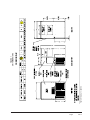
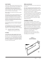
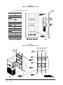
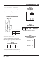
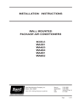
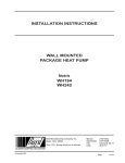
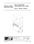
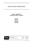
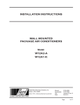
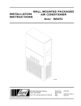
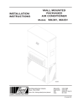
INSTALLATION INSTRUCTIONS
WALL MOUNTED
PACKAGE AIR CONDITIONERS
Model:
WA121
Bard Manufacturing Company, Inc.
Bryan, Ohio 43506
Since 1914....Moving ahead just as planned.
© Copyright 2002
Manual :
Supersedes:
File:
Date:
2100-234I
2100-234H
Volume III Tab 16
08-01-07
Manual
Page
2100-234I
1 of 17
CONTENTS
Getting Other Informations and Publications
3
Wall Mount General Information
Air Conditioner Wall Mount Model Nomenclature ..... 4
Shipping Damage ..................................................... 6
General ..................................................................... 6
Duct Work ................................................................. 7
Filters ........................................................................ 7
Fresh Air Intake ........................................................ 7
Condensate Drain ..................................................... 7
Installation Instructions
Wall Mounting Information ........................................ 8
Mounting the Unit ..................................................... 8
Wiring – Main Power .............................................. 12
Wiring – Low Voltage Wiring .................................. 12
Figures
Figure 1
Figure 2
Figure 3
Figure 4
Figure 5
Figure 6
Figure 7
Figure 8
Start Up
Important Installer Note .......................................... 14
Service Hints .......................................................... 14
High Pressure Switch ............................................. 14
Sequence of Operation ........................................... 14
Compressor Control Module ................................... 14
Adjustments ............................................................ 15
Pressure Service Ports ........................................... 15
Troubleshooting
Fan Blade Setting Dimension ................................. 16
Refrigerant Charge ................................................. 16
Pressure Tables ...................................................... 17
Option Field Installed Accessories .......................... 17
Tables
Unit Dimensions ...................................... 5
Blower Damper Assembly ....................... 7
Mounting Instructions .............................. 9
Wall Mounting Instructions ................... 10
Wall Mounting Instructions ................... 10
Common Wall Mounting
Instructions ............................................ 11
Low Voltage Wiring ............................... 13
Fan Blade Setting Dimensions ............. 16
Table 1
Table 2
Table 3
Table 4
Table 5
Table 6
Table 8
Table 7
Table 9
Table 10
Table 11
Manual 2100-234I
Page
2 of 17
Electric Heat Table .................................. 4
Electrical Specifications .......................... 6
Thermostat Wire Size ........................... 12
Wall Thermostats .................................. 12
Fan Blade Dimensions .......................... 16
Suction Line Temperatures ................... 16
Recommended Operating Ranges ....... 16
Indoor Blower Performance .................. 16
Maximum ESP of Operation
Electric Heat Only ................................. 16
Pressure Table - Cooling ...................... 17
Optional Accessories ............................ 17
GETTING OTHER INFORMATION and PUBLICATIONS
These publications can help you install the air
conditioner or heat pump. You can usually find these at
your local library or purchase them directly from the
publisher. Be sure to consult current edition of each
standard.
For more information, contact these
publishers:
ACCA
Air Conditioning Contractors of America
1712 New Hampshire Avenue NW
Washington, DC 20009
Telephone: (202) 483-9370
Fax: (202) 234-4721
ANSI
American National Standards Institute
11 West Street, 13th Floor
New York, NY 10036
Telephone: (212) 642-4900
Fax: (212) 302-1286
National Electrical Code ...................... ANSI/NFPA 70
Standard for the Installation of .......... ANSI/NFPA 90A
Air Conditioning and
Ventilating Systems
Standard for Warm Air Heating ........ ANSI/NFPA 90B
and Air Conditioning Systems
Load Calculation for ............................ ACCA Manual J
Residential Winter and
Summer Air Conditioning
Duct Design for ................................. ACCA Manual D
Residential Winter and
Summer Air Conditioning
and Equipment Selection
ASHRAE American Society of Heating, Refrigerating
and Air Conditioning Engineers, Inc.
1791 Tullie Circle, NE
Atlanta, GA 30329-2305
Telephone: (404) 636-8400
Fax: (404) 321-5478
NFPA
National Fire Protection Association
Batterymarch Park
P.O. Box 9101
Quincy, MA 02269-9901
Telephone: (800) 344-355
Fax: (617) 984-7057
Manufactured under the following U.S. patent numbers:
5,485,878; and 5,301,744
Manual
Page
2100-234I
3 of 17
WALL MOUNT GENERAL INFORMATION
AIR CONDITIONER WALL MOUNT MODEL NOMENCLATURE
WA
MODEL NUMBER
12
1
–
A
00
X
X
X
X
X J
CONTROL MODULES
E - Low Ambient Control
J - Telecommunication
CAPACITY
12 - 1 Ton
REVISIONS
VOLTS & PHASE
A - 230/208/60/1
K - 115/60/1
KW
00 - No KW
02 - 2.2 KW
03 - 3.6 KW
05 - 5.0 KW
COIL OPTIONS
X - Standard Coils
COLOR OPTIONS
X - Beige
4 - Buckeye Gray
VENTILATION OPTIONS
X - Barometric Fresh Air
Damper (Standard)
B - Blank-off Plate
E - Economizer (Internal) - Fully FILTER OPTIONS
Modulating with Exhaust
X - One Inch Throwaway
(Standard)
P - Two Inch Pleated
OUTLET OPTIONS
X - Front
TABLE 1
ELECTRIC HEAT TABLE
Models
WA121-A
240V
KW
A
1
B TU
WA121-K
208V
A
1
B TU
02
03
15.0
12,760
13.0
9,705
05
20.8
17,540
18.1
13,275
1 With blower watts included
Manual 2100-234I
Page
4 of 17
WA121-G
120V
240V
220V
A
1
B TU
A
1
B TU
A
1
B TU
18.3
7,985
10.0
8,665
9.1
7,300
15.0
12,760
13.8
10,800
Manual
Page
2100-234I
5 of 17
FACTORY BUILT AT 5 INCHES
FIGURE 1
UNIT DIMENSIONS
TABLE 2
ELECTRICAL HEAT SPECIFICATIONS
SINGLE CIRCUIT
3
1
2
2
Field Pow er
Wire Siz e
Ground
Wire Siz e
Rated Volts
an d
P h ase
No. Field
P o w er
Circuits
Minimum
Circuit
Ampacity
Maximum
External Fuse
or Circuit
Breaker
WA121-A00
A 03
A 05
230/208-1
1
1
1
8
20
27
15
20
30
14
12
10
14
12
10
WA121-K00
K 02
115-1
1
1
17
25
25
30
10
10
10
10
WA121-G00
G02
G03
220-50-1
1
1
1
7
13
20
15
15
20
14
14
12
14
14
12
Models
Maximum size of the time delay fuse or HACR type circuit breaker for protection of field wiring conductors.
Based on 75° C copper wire. All wiring must conform to NEC and all local codes.
These “Minimum Circuit Ampacity” values are to be used for sizing the field power conductors. Refer to the
National Electrical Code (latest revision), article 310 for power conductor sizing.
CAUTION: When more than one field power conductor circuit is run through one conduit, the conductors
must be derated. Pay special attention to note 8 of table 310 regarding Ampacity Adjustment Factors when
more than 3 conductors are in a raceway.
SHIPPING DAMAGE
Upon receipt of equipment, the carton should be checked
for external signs of shipping damage. If damage is
found, the receiving party must contact the last carrier
immediately, preferably in writing, requesting inspection
by the carrier’s agent.
GENERAL
The equipment covered in this manual is to be installed
by trained, experienced service and installation
technicians.
The refrigerant system is completely assembled and
charged. All internal wiring is complete.
The unit is designed for use with or without duct work.
Flanges are provided for attaching the supply and return
air ducts.
These instructions explain the recommended method to
install the air cooled self-contained unit and the electrical
wiring connections to the unit.
Manual 2100-234I
Page
6 of 17
These instructions and any instructions packaged with
any separate equipment required to make up the entire air
conditioning system should be carefully read before
beginning the installation. Note particularly “Starting
Procedure” and any tags and/or labels attached to the
equipment.
While these instructions are intended as a general
recommended guide, they do not supersede any national
and/or local codes in any way. Authorities having
jurisdiction should be consulted before the installation is
made. See Page 3 for information on codes and
standards.
Size of unit for a proposed installation should be based
on heat loss calculation made according to methods of
Air Conditioning Contractors of America (ACCA). The
air duct should be installed in accordance with the
Standards of the National Fire Protection Association for
the Installation of Air Conditioning and Ventilating
Systems of Other Than Residence Type, NFPA No. 90A,
and Residence Type Warm Air Heating and Air
Conditioning Systems, NFPA No. 90B. Where local
regulations are at a variance with instructions, installer
should adhere to local codes.
DUCT WORK
FRESH AIR INTAKE
All duct work, supply and return must be properly sized
for the design air flow requirement of the equipment. Air
Conditioning Contractors of America (ACCA) is an
excellent guide to proper sizing. All duct work or
portions thereof not in the conditioned space should be
properly insulated in order to both conserve energy and
prevent condensation or moisture damage.
All units are built with fresh air inlet slots punched in the
service panel.
Refer to Table 9 for maximum static pressure available
for duct design.
Design the duct work according to methods given by the
Air Conditioning Contractors of America (ACCA).
When duct runs through unheated spaces, it should be
insulated with a minimum of one inch of insulation. Use
insulation with a vapor barrier on the outside of the
insulation. Flexible joints should be used to connect the
duct work to the equipment in order to keep the noise
transmission to a minimum.
Ducts through the walls must be insulated and all joints
taped or sealed to prevent air or moisture entering the
wall cavity.
Some installations may not require any return air duct. It
is recommended that on this type of installation that a
filter grille be located in the wall. Filters must be of
sufficient size to allow a maximum velocity of 400 FPM.
NOTE: If no return air duct is used, applicable
installation codes may limit this cabinet to
installation only in a single story structure.
FILTERS
A one inch throwaway filter is supplied with each unit.
The filter slides into position making it easy to service.
This filter can be serviced from the outside by removing
the service door. A 2-inch pleated filter is also available
as an optional accessory. The internal filter brackets are
adjustable to accommodate the 2-inch filter by bending
the metal tabs holding the 1-inch filter down. There are
two tabs on each side of the filter.
If the unit is equipped with a fresh air damper assembly,
the assembly is shipped already attached to the unit. The
damper blade is locked in the closed position. To allow
the damper to operate, the maximum and minimum blade
position stops must be installed. See Figure 2.
All capacity, efficiency and cost of operation information
as required for Department of Energy “Energyguide” Fact
Sheets is based upon the fresh air blank-off plate in place
and is recommended for maximum energy efficiency.
The blank-off plate is available upon request from the
factory and is installed in place of the fresh air damper
shipped with each unit.
CONDENSATE DRAIN
This unit employs an automatic condensate disposal
system consisting of a base drain pan, drain valve and fan
blade with slinger ring. A plastic drain hose extends from
the evaporator drain pain at the top of the unit to the base
drain pan at the bottom. At temperatures above 40°, the
drain valve located between the condenser coil and fan
shroud is closed allowing water to build up in the base to
a height of 5/8" to 3/4". The fan blade with slinger then
rotates in this water and throws the water onto the
condenser coil. This disposes of the water by
evaporating it on the hot condenser.
At temperatures below 40°, the drain valve opens
draining the base pan and preventing freeze ups that
could damage the coil or fan blade.
FIGURE 2
FRESH AIR DAMPER
Manual
Page
2100-234I
7 of 17
INSTALLATION INSTRUCTIONS
WALL MOUNTING INFORMATION
1. These units are secured by wall mounting brackets
which secure the unit to the outside wall surface at
both sides.
2. On wood frame walls, the wall construction must be
strong and rigid enough to carry the weight of the
unit without transmitting any unit vibration.
3. Concrete block walls must be thoroughly inspected
to insure that they are capable of carrying the weight
of the installed unit.
MOUNTING THE UNIT
1. Two holes, for the supply and return air openings,
must be cut through the wall as shown in Figure 3.
NOTE:
If the combination SUPPLY / RETURN
Grille Assembly model CRSG-1 is to be used
in conjunction with this unit a different size
wall opening is required.
Manual 2100-234I
Page
8 of 17
2. Locate and mark lag bolt locations, if desired. See
Figure 3.
3. Hook top rain flashing under back bend of top. Top
rain flashing is shipped attached to the back of the
unit on the right side.
4. Position unit in opening and secure with 5/16 lag
bolts; use 7/8 inch diameter flat washers on the lab
bolts.
5. Secure rain flashing to wall and caulk across entire
length of top. See Figure 3.
6. For additional mounting rigidity, the return air and
supply air frames or collars can be drilled and
screwed or welded to the structural wall itself
(depending upon wall construction). Be sure to
observe required clearance if combustible wall.
7. On side-by-side installations, maintain a minimum of
20 inches clearance on right side to allow access to
control panel and allow proper airflow to outdoor
coil. Additional clearance may be required to meet
local or national codes.
Manual
Page
2100-234I
9 of 17
FIGURE 3
MOUNTING INSTRUCTIONS
FIGURE 4
WALL MOUNTING INSTRUCTIONS
SEE FIGURE 3 - MOUNTING INSTRUCTIONS
FIGURE 5
WALL MOUNTING INSTRUCTIONS
SEE UNIT DIMENSIONS, FIGURE 1,
FOR ACTUAL DIMENSIONS
Manual 2100-234I
Page
10 of 17
FIGURE 6
COMMON WALL-MOUNTING INSTALLATIONS
Manual
Page
2100-234I
11 of 17
WIRING – MAIN POWER
WIRING – LOW VOLTAGE WIRING
Refer to the unit rating plate for wire sizing information
and maximum fuse or “HACR” type circuit breaker size.
Each outdoor unit is marked with a “Minimum Circuit
Ampacity”. This means that the field wiring used must
be sized to carry that amount of current. Depending on
the installed KW of electric heat, there may be two field
power circuits required. If this is the case, the unit serial
plate will so indicate. All models are suitable only for
connection with copper wire. Each unit and/or wiring
diagram will be marked “Use Copper Conductors Only”.
These instructions must be adhered to. Refer to the
National Electrical Code (NEC) for complete current
carrying capacity data on the various insulation grades of
wiring material. All wiring must conform to NEC and all
local codes.
230/208, 1 phase equipment use dual primary voltage
transformers. All equipment leaves the factory wired on
240V tap. For 208V operation, reconnect from 240V to
208V tap. The acceptable operating voltage range for the
240 and 208V taps are:
The electrical data lists fuse and wire sizes (75°C copper)
for all models, including the most commonly used heater
sizes. Also shown are the number of field power circuits
required for the various models with heaters.
Five (5) wires should be run from thermostat subbase to
the 24V terminal board in the unit. A five conductor, 18
gauge copper, color-coded thermostat cable is
recommended. The connection points are shown in
Figure 7.
TAP
RANGE
240
253 - 216
208
220 - 187
NOTE: The voltage should be measured at the field power
connection point in the unit and while the unit is
operating at full load (maximum amperage
operating condition).
The unit rating plate lists a “Maximum Time Delay Relay
Fuse” of “HACR” type circuit breaker that is to be used
with the equipment. The correct size must be used for
proper circuit protection and also to assure that there will
be no nuisance tripping due to the momentary high
starting current of the compressor motor.
TABLE 3
THERMOSTAT WIRE SIZE
Transformer
VA
40
FLA
Wire Gauge
Maximum Distance
in Feet
2.3
20 Gauge
18 Gauge
16 Gauge
14 Gauge
12 Gauge
45
60
100
160
250
TABLE 4
WALL THERMOSTAT
Thermostat
Predominate Features
1 stage Cool, 1 stage Heat
8403-057
Electronic Non-Programmable
TH5220D1153
Auto or Manual changeover
2 stage Cool, 2 stage Heat
8403-058
Electronic Non-Programmable
TH5220D1151
Auto or Manual changeover
8403-060
(1120-445)
Manual 2100-234I
Page
12 of 17
3 stage Cool; 3 stage Heat
Programmable/Non-Programmable Electronic
HP or Conventional
Auto or Manual changeover
FIGURE 7
LOW VOLTAGE WIRING
Manual
Page
2100-234I
13 of 17
START UP
IMPORTANT INSTALLER NOTE
For improved start up performance, wash the indoor coil
with a dishwasher detergent.
SERVICE HINTS
the delay on make is complete and the high pressure
switch (and low pressure switch if employed) is closed,
the compressor contactor is energized. Upon shutdown
the delay on break time starts and prevents restart until
the delay on break and delay on make periods have
expired.
1. Caution owner to maintain clean air filters at all
times. Also not to needlessly close off supply and
return air registers. This reduces airflow through the
system which shortens equipment service life as well
as increasing operation costs.
During routine operation of the unit with no power
interruptions the compressor will operate on demand with
no delay.
2. The unit is equipped with a high pressure cut out
switch.
HIGH PRESSURE SWITCH
If the high pressure switch opens, the compressor
contactor will de-energize immediately. The lockout
timer will go into a soft lockout and stay in soft lockout
until the high pressure switch closes and the delay on
break time has expired. If the high pressure switch opens
again in this same operating cycle the unit will go into
manual lockout condition and the alarm relay circuit will
energize. Recycling the wall thermostat resets the manual
lockout.
The WA121 models are supplied with a remote reset
high pressure switch. If tripped, this pressure switch may
be reset by turning the thermostat off then back on again.
Low Pressure Switch, Bypass and Lockout
Sequence
3. Check all power fuses or circuit breakers to be sue
they are the correct rating.
4. Periodic cleaning of the outdoor coil to permit full
and unrestricted airflow circulation is essential.
SEQUENCE OF OPERATION
COOLING – Circuit R-Y makes at thermostat pulling in
compressor contactor, starting the compressor and
outdoor motor. The G (indoor motor) circuit is
automatically completed on any call for cooling
operation or can be energized by manual fan switch on
subbase for constant air circulation. On a call for
heating, circuit R-W1 make at the thermostat pulling in
heat contact for the strip heat and blower operation.
COMPRESSOR CONTROL MODULE
The compressor control module is optional on the models
covered by this manual. The compressor control is an
anti-short cycle/lockout timer with high and low pressure
switch monitoring and alarm relay output.
Adjustable Delay on Make and Break Timer
On initial power up or any time power is interrupted to
the unit the delay on make period begins, which will be 2
minutes plus 10% of the delay on break setting. When
Manual 2100-234I
Page
14 of 17
High Pressure Switch and Lockout Sequence
If the low pressure switch opens for more than 120
seconds, the compressor contactor will de-energize and
go into a soft lockout. Regardless the state of the low
pressure switch, the contactor will reenergize after the
delay on make time delay has expired. If the low
pressure switch remains open, or opens again for longer
that 120 seconds, the unit will go into manual lockout
condition and the alarm relay circuit will energize.
Recycling the wall thermostat resets the manual lockout.
Alarm Relay Output
Alarm terminal is output connection for applications
where alarm relay is employed. This terminal is powered
whenever compressor is locked out due to HPC or LPC
sequences as described.
NOTE: Both high and low pressure switch controls are
inherently automatic reset devices. The high
pressure switch and low pressure switch cut out
and cut in settings are fixed by specific air
conditioner or heat pump unit model. The lockout
features, both soft and manual, are a function of
the Compressor Control Module.
ADJUSTMENTS
PRESSURE SERVICE PORTS
Adjustable Delay on Make and Delay on Break
Timer
High and low pressure service ports are installed on all
units so that the system operating pressures can be
observed. Pressure chart can be found later in the manual
covering all models. It is imperative to match the correct
pressure chart to the unit by model number.
The potentiometer is used to select Delay on Break time
from 30 seconds to 5 minutes. Delay of Make (DOM)
timing on power up and after power interruptions is equal
to 2 minutes plus 10% of Delay of Break (DOB) setting:
0.5 minute (30 seconds)
1.0 minute (60 seconds)
2.0 minute (120 seconds)
3.0 minute (180 seconds)
4.0 minute (240 seconds)
5.0 minute (300 seconds)
DOB = 123 second
DOB = 126 second
DOB = 132 second
DOB = 138 second
DOB = 144 second
DOB = 150 second
DOM
DOM
DOM
DOM
DOM
DOM
During routine operation of the unit with no power
interruptions the compressor will operate on demand with
not delay.
Typical Settings for Dual Unit Installation:
Unit No. 1: DOB set at 2 minutes, and DOM is 132
seconds.
Unit No. 2: DOB set at 4 minutes, and DOM is 144
seconds.
Manual
Page
2100-234I
15 of 17
TROUBLESHOOTING
TABLE 7
INDOOR BLOWER
PERFORMANCE
CFM @ 230V
FAN BLADE SETTING DIMENSIONS
Show in Figure 8 is the correct fan blade setting
dimension for proper air delivery across the outdoor coil.
Any service work requiring removal or adjustment in the
fan and/or motor area will require that the dimension
below be checked and blade adjusted in or out on the
motor shaft accordingly.
WA121
230V
E.S.P.
in H2O
FIGURE 8
FAN BLADE SETTING DIMENSION
Dry / Wet
.0
.1
.2
.3
.4
530
485
440
390
325
/
/
/
/
/
500
460
425
375
300
TABLE 8
RATED CFM AND ESP
RECOMMENDED AIRFLOW RANGE
TABLE 5
FAN BLADE DIMENSION
Model
Dimension A
WA121
1/2"
Rated
CFM*
Rated
ESP*
Recommended
Airflow Range
WA121
400
.25
500 - 300
* Rated CRM and ESP on high speed tap.
TABLE 9
MAXIMUM ESP OF OPERATION
ELECTRIC HEAT ONLY
REFRIGERANT CHARGE
The correct system R-22 charge is shown on the unit
rating plate. Optimum unit performance will occur with a
refrigerant charge resulting in a suction line temperature
6" from compressor as shown in Table 6.
TABLE 6
SUCTION LINE TEMPERATURE
Model
Rated
Airflow
95o OD
Temperature
82o OD
Temperature
WA121
400
54 - 56
65 - 67
The suction line temperatures in Table 6 are based upon
80° F dry bulb / 67° F wet bulb (50% R.H.) temperature
and rated airflow across the evaporator during cooling
cycle.
Manual 2100-234I
Page
16 of 17
Model
Model
ESP
WA121-A00
A 03
A 05
.35
.35
.35
WA121-K00
K 02
.35
.35
WA121-G00
G02
G03
.35
.35
.35
Values shown are for units equipped with STD
1" throwaway filters. Derate ESP by .15 for 2"
pleated filters.
TABLE 10
PRESSURE TABLE
COOLING
Model
WA121
Air Temperature Entering Outdoor Coil oF
Return Air
Temperature
Pressure
75o
75 deg. D B
62 deg. WB
Low S i de
High Side
72
187
80 deg. D B
67 deg. WB
Low S i de
High Side
85 deg. D B
72 deg. WB
Low S i de
High Side
80o
85o
90o
95o
100o 105o 100o
115o
74
201
76
216
79
232
81
248
83
265
86
282
88
300
91
319
76
192
79
207
82
222
84
238
87
255
90
272
92
290
95
309
97
328
81
198
85
214
88
230
91
247
94
264
97
282
99
300
102
319
104
339
Model
Description
WA121
TABLE 11
OPTIONAL FIELD INSTALLED ACCESSORIES
BOP-1A
Blank Off Plate
X
BFAD-1
Barometric Fresh Air Damper
X
EIFM-1
Economizer with Exhaust
X
CMA-6
Low Ambient Control
X
CMA-20
LPC + TDR + LAC
X
Manual
Page
2100-234I
17 of 17