1
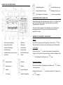
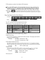
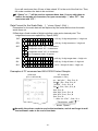
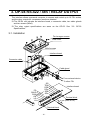
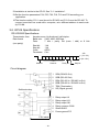
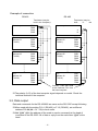
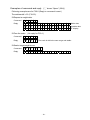
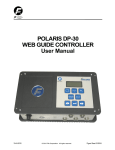
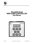
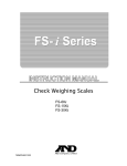
A&D Instruments Ltd. German Sales Office Große Straße 13b 22926 Ahrensburg Tel: 0049 4102 459230 Fax:0049 4102 459231 Bedienungsanleitung www.aandd-eu.net [email protected] FS-6Ki FS-15Ki FS-30Ki +/- Waage, eichfähig EINGABE TOLERANZWERT EINLEITUNG Drücken Sie die Taste Herzliche Gratulation zum Erwerb dieser CE geprüften Waage. Diese ermöglicht es Ihnen, eine Stückzahl und das genaue Gewicht zu ermitteln. Das Modell A FS-30 Ki CH ist einfach zu bedienen, präzise und robust. . Legen Sie den gewünschten Artikel auf die Wiegeplatte und bestätigen Sie mit der Taste . Wenn das Gewicht des Artikels bekannt ist, können Sie auch anstatt den Artikel auf die Wiegeplatte zu legen, den Damit die Waage einwandfrei funktioniert, empfehlen wir Ihnen, die nachfolgende Bedienungsanleitung sorgfältig zu lesen. Sollwert über die Zahlentastatur eingeben. Drücken Sie dadurch nach der Taste die Taste um zur Zahlenebene der Tastatur zu kommen. Geben Sie das Gewicht ein und bestätigen Sie mit der STORED. Taste. In der Anzeige erscheint Drücken Sie nun die Taste und geben Sie die tolerierte Abweichung (Tiefstwert) über die Zahlentastatur ein (ohne KEY Taste) und bestätigen die Eingabe mit der Taste. In der Anzeige erscheint wiederum STORED. Dasselbe machen Sie mit der Abweichung über dem Sollwert (Höchstwert). Drücken Sie entsprechend die ein und bestätigen mit der Taste Taste, geben den Wert über die Zahlentasten . Wenn Sie nun wägen erscheint bei einem Wert unter der Toleranzgrenze das rote Licht, innerhalb der Toleranz das grüne Licht und bei Überlast das gelbe Licht. EINGABE TOLERANZWERT MIT SPEICHERN Gehen Sie wie gleich vorherigen Abschnitt beschrieben. Nachdem Sie die Toleranzwerte HI und LO eingegeben haben, drücken Sie nun die Taste und legen den gewünschten Speicherort über die Zahlentastatur fest (zwischen 1-99). ABRUFEN AB SPEICHER Durch Drücken der Taste und der entsprechenden Zahlentaste (1-99) können Sie die gespeicherten Werte auf den verschiedenen Positionen jederzeit abrufen. Schliessen Sie die Wahl mit der Taste ab. Die Waage zeigt kurz die Toleranzwerte und ist dann zum Wiegen bereit. INSTALLATION UND INBETRIEBNAHME Die Waage sollte immer an einem Standort benützt werden, welcher frei von übermässigem Luftzug, ätzenden Materialien, Erschütterungen und extremen Temperatur- / Feuchtigkeitsschwankungen ist. Diese Faktoren können die Messwerte negativ beeinflussen. vermeiden Sie (die Waage) in der Nähe von offenen Fenstern / Türen infolge Durchzug, raschen Temperaturschwankungen oder direkter Sonneneinstrahlung zu platzieren. in der Nähe von Kühlgeräten oder Heizungen zu platzieren in der Nähe von vibrierenden oder rotierenden Geräten aufzustellen in der Nähe von magnetischen Feldern oder Geräten die magnetische Strahlung erzeugen aufzustellen auf unebenen Arbeitsflächen zu installieren etwas auf die Wiegeplatte fallen lassen, auf die Schale zu springen oder die Waage fallen lassen. Solche Schläge können ungenaues Gewicht und/oder Beschädigungen an der Waage hervorrufen Lösungsmittel wie z.B. Benzin oder Verdünner zu verwenden um die Waage zu reinigen Schliessen Sie die Waage mit dem mitgelieferten Anschlusskabel am Stromnetz an. Betreiben Sie das Gerät ausschliesslich mit dem mitgelieferten Anschlusskabel. Wird die Waage über längere Zeit nicht gebraucht, soll sie vom Stromnetz getrennt werden. Schalten Sie die Waage mit der Taste ein und warten Sie bis die Anzeige auf Null steht. Achten Sie darauf, dass dabei kein Gewicht auf der Wiegeplatte liegt. Falls die Waage eine Abweichung zeigt, drücken Sie die Nachnullen. Taste zum ANZEIGE UND TASTENFUNKTIONEN Eingabe Mustergewicht Gewichtseinheit (g oder kg) Eingabe Sollgewicht (Dezimal) Aufruf Sollgewicht / HI-LO Angaben Bestätigung / Drucken (opt.) Löscht numerische Eingabe AKKUBETRIEB (OPTIONAL ERHÄLTLICH) Niedrige Akkuanzeige: Wenn in der Anzeige oben rechts kurz „LbI“ erscheint, muss der Akku raschmöglichst wie möglich nachgeladen werden um einwandfreie Wiegeergebnisse zu gewährleisten. Akku wieder aufladen: Schliessen Sie den Netzadapter an. Die Anzeige für den Ladevorgang erscheint Rot. Wenn sie auf Grün wechselt, ist der Akku voll geladen(ca. 8 Stunden). TARIEREN / VOR-TARA ABZUG / TARA LÖSCHEN Tarieren 1 Feld für die Gewichtsanzeige 7 Nullindikator 2 Anzeige Gewichtseinheit 8 Nettoanzeige Legen Sie eine Verpackung auf die Wiegeplatte und drücken Sie die Taste. Nach dem Einfüllen der Artikel können Sie das Nettogewicht vom Display ablesen. 3 Analoge Gewichtsanzeige 9 Vortara-Anzeige Vor-Tara Abzug 4 Ueberlast Anzeige 10 Drucker-Anzeige 5 Vergleichsanzeigen (rot, grün, orange) 11 Akku-Warnzeichen (opt.) 6 Levelanzeige 12 Tastatur Drücken Sie die Taste und geben Sie das bekannte Taragewicht über die Tastatur ein. Falls Sie einen Fehler gemacht haben, löschen Sie die Eingabe mit der Taste. Bestätigen Sie die Eingabe mit der Taste. Waage einschalten Höchstwert Löschen des Tarawertes Nullanzeige oder +- Tiefstwert Nehmen Sie alle Artikel von der Wiegeplatte und drücken Sie die Tarawert ist gelöscht. Tarataste Speichert Sollgewicht Vor-Taraabzug Umschalt. Analogdisplay Anstelle können Sie auch die mit bestätigen. Taste. Der Taste drücken und den Wert „0“ eingeben und FS-i Series Check Weighing Scales Options OP-02 OP-03 OP-04 1WMPD4001368 Contents 1. OP-02 BATTERY .............................................................................................. 3 1-1. Using the OP-02 SLA Battery.................................................................... 3 2. OP-03 RS-232C / RELAY OUTPUT ................................................................. 5 2-1. Installation ................................................................................................. 5 2-2. OP-03 Specifications ................................................................................. 6 2-3. Command Mode........................................................................................ 8 2-4. Using UFC (Universal Flex Coms) function............................................. 12 3. OP-04 RS-422 / 485 / RELAY OUTPUT ......................................................... 15 3-1. Installation ............................................................................................... 15 3-2. OP-04 Specifications ............................................................................... 16 3-3. Data output.............................................................................................. 17 This Manual and Marks All safety messages are identified by the following, “WARNING” or “CAUTION”, of ANSI Z535.4 (American National Standard Institute: Product Safety Signs and Labels). The meanings are as follows: WARNING CAUTION A potentially hazardous situation which, if not avoided, could result in death or serious injury. A potentially hazardous situation which, if not avoided, may result in minor or moderate injury. This is a hazard alert mark. Note This manual is subject to change without notice at any time to improve the product. No part of this manual may be photocopied, reproduced, or translated into another language without the prior written consent of the A&D Company. Product specifications are subject to change without any obligation on the part of the manufacture. Copyright 2006 -2- 1. OP-02 BATTERY 1-1. Using the OP-02 SLA Battery The scale can be operated with an SLA (Sealed Lead Acid) battery that will be commercially available. The scale (with no other options) can be operated with a fully charged battery for; LCD backlight OFF and Comparator light OFF: approximately 80 hours LCD backlight OFF and Comparator light ON: approximately 55 hours LCD backlight ON and Comparator light ON: approximately 25 hours The battery will take about 15 hours to be fully charged. The battery life will vary depending on how the scale is used, the ambient temperature and so on. Use a Yuasa Battery NP4-6 (6V, 4Ah). There will be risk of explosion if the battery is connected improperly or replaced with the incorrect type. Dispose of a used battery according to the local laws and regulations. Installing the battery Do not remove rubber O-rings. Hexagon head screws Battery NP4-6 Rear cover “-” (BLACK) wire M3x8 screws Battery support “+” electrode (RED) “+” (RED) wire -3- “-” electrode (BLACK) 1. Disconnect the main power cord from the outlet. 2. Remove the ten hexagon head screws and open the rear cover. Take care not to drop the rear cover or the wires connecting between front display and rear cover will be damaged. 3. Loosen the screws fixing the battery support and remove it. 4. Connect the wires inside the display pod to the battery. Be sure to connect RED wire to positive (+ / RED) terminal and BLACK wire to negative (- / BLACK) terminal. Or there is a risk of explosion. 5. Place the battery into the rear cover and fix with screws and battery support that removed at step 3 above. 6. Attach the rear cover to the front display firmly using the ten hexagon head bolts. 7. Connect the main power cord to the outlet. 8. Press the ON/OFF key and check that the scale works normally. 9. Disconnect the main power cord again and check that the scale still works. Charging the battery When the weight display shows “lb1”, the battery voltage is low in voltage and should be recharged. Connect the main power cord to the outlet. The charging process will start while the scale is powered on or not. When the battery is getting close to the low battery, the annunciator (PRECAUTION AGAINST LOW BATTERY) will come on. Prepare to charge the battery. The scale can be used while the battery is charging. After fully charged, the scale will change the charging process to trickle charge automatically. The battery cannot be charged with the OP-04 in operation. Turn the power off to charge. Charge the battery at a temperature between 0°C (32°F) and 40°C (104°F). Preferably 5°C (41°F) ~ 35°C (95°F) is recommended. Charge the battery when using for the first time. The battery must be recharged regularly if the scale is not used for a long period of time. Every 3 months in a warmer area and every 6 months in a cooler area will be needed. -4- 2. OP-03 RS-232C / RELAY OUTPUT This interface allows the FS-i series to be connected with a multifunction printer or a personal computer, and the relay outputs for comparator result are obtained. The OP-03 unit includes an interface board, a connector cable, a cable gland and two screws (M3x6). 2-1. Installation Ten hexagon screws Rear cover M3x6 screws Interface board Connector cable Cable gland From external device Main board COM OK LO HI FG SHLD SG DSR TXD RXD Interface board 6 mm (AWG 26~16) Terminal block -5- 1. Disconnect the main power cord from the outlet. 2. Remove the ten hexagon screws and open the rear cover. 3. Connect the cable from external device through the cable gland to the terminal blocks on the interface board. Also connect a yellow/green wire inside the display pod directly to “FG” on the terminal block. Take care not to drop the rear cover or the wires connecting between front display and rear cover will be damaged. 4. Connect the connector cable included in the OP-03 to the connectors on the interface board and the main board inside the display pod. 5. Fix the interface board with 2 M3 x 6 screws included in the OP-03. 6. Tighten the cable gland and attach the rear cover to the front display firmly using the ten hexagon bolts. 7. Connect the main power cord to the outlet. 8. Set the function parameters F04, F05, F06, F18, F19 and F20 according your application. The OP-03 RS-232C must have settings F18-00 and F19-0. 2-2. OP-03 Specifications RS-232C Specification Transmission form Data format Asynchronous, bi-directional, half-duplex Baud rate: 2400, 4800, 9600 bps Data: 7 bits + parity 1bit (even / odd) or 8 bits (non-parity) Start bit: Stop bit: Code: Terminator: LSB 0 1 bit 1 bit ASCII CRLF 1 Start bit 2 3 4 MSB 5 6 Data bit Maximun rating of the Relau Outoput The maximum rating of the replay output is as follows. Maximum voltage: 50V DC Maximum current: 100 mA DC Maximum ON resistance: 8Ω -6- Parity bit 1 (-15V~-5V) 0 (5V~15V) Stop bit Circuit diagram 1 2 3 4 5 6 Receive data RXD Transmit data TXD Data set ready DSR Signal ground SG Shield SHLD Frame ground FG FS-i is designed as DCE (Data Communication Equipment). Solid sate relay 1 2 3 4 Relay output HI Relay output LO Relay output OK Relay common COM 0 . FS-i inside Data format S T , + 0 0 0 Header 0 0 0 _ Data k Unit g CR LF Terminator There are 3 headers for the weighing data. ST: US: OL: Stable weighing data Unstable weighing data Out of weighing range The data consists of 9 characters including polarity and decimal point. There are 5 units. _ k g: _ _ g: _ l b: _ o z: _ _ %: Weighing unit “kg” Weighing unit “g” Weighing unit “lb” Weighing unit “oz” HI/LO limit % (F07-2) Example of data Weighing data “kg” (+) S T , + 0 0 1 2 . 3 4 5 _ k g CR LF Weighing data “g” (-) S T , - 0 0 0 1 2 3 4 _ _ g CR LF -7- 0 Out of rage (+) O L , + 9 9 9 9 9 9 9 9 _ k g CR LF Data output mode (F06) Stream Mode (F06-0) Data is sent continuously. The data-update rate is approximately 20 times per second. But for 2400 bps, it is too slow to send 20 times. If necessary, set the baud rate 4800 bps or more. Command Mode (F06-1) The scale is controlled by commands that come from an external device, computer etc. See “2-3. Command mode” in detail. Print Key Mode (F06-2) When the weight display is stable, data is sent by pressing the PRINT key. The PRINT annunciator will turn on for a short while when the data has been sent. Auto-print Mode + data (F06-3) Data is sent if the weight display is stable at +5d (d = weighing display division) and above. The next transmission can not occur until after the weight display falls below +5d. Auto-print Mode +/- data (F06-4) Data is sent if the weight display is stable at ±5d (d = weighing display division) and above/below. The next transmission can not occur until after the weight display falls between –5d and +5d. Baud Rate (F04) Select the baud rate according to the device to be connected. 2400 bps (F04-0) Select 2400 bps to connect with an AD-8121. 4800 bps (F04-1) 9600 bps (F04-2) 2-3. Command Mode In the command mode, the scale is controlled by commands that come from an external device, computer etc. Command List Command Q Z T U D PT Definition Send data immediately. Zero the scale when the weight is stable. Tare the scale when the data is stable. Switch the weighing unit. Switch the analog sweep display mode. Set a known (preset) tare weight. -8- Notes Same as the Same as the Same as the Same as the ZERO TARE UNITS DISP. key. key. key. key. Set “+” and 6 digit number without decimal point. Command CT ?PT ?TR ?OK ?HI ?LO OK HI LO Definition Notes Including preset tare. Clear tare weight. Send a preset tare weight in-use. Send a tare weight in-use. Send a target weight in-use. Send a HI limit value or upper limit weight in-use. Send a set value. Send a LO limit value or lower limit weight in-use. Set a target weight. Set “+” and 6 digit (5 digit for %) Set a HI limit value or upper limit weight. number without decimal point. Set a LO limit value or lower limit weight. ML Store the comparator limits into the specified memory number. CM Clear the contents of specified memory number. Examples of command and reply (“_” shows “Space” (20H).) Examples below are for F20-0 (Reply to command is sent.) Request a weight data. Command Q C LF Reply S T , + 0 0 1 2 . U S , + 0 0 0 7 . O L . Zero the scale. , + 9 9 9 9 3 4 5 _ k g C LF Stable Positive Data 8 9 0 _ k g C LF Unstable Positive Data 9 9 9 _ k g C LF ‘E’ display (No reply for F20-1.) Command Z C LF Reply Z C LF The scale is within the zero range and stable. Tare the scale. (No reply for F20-1.) Command T C LF Reply T C LF The scale shows positive and stable data. Switch the weighing unit. (No reply for F20-1.) Command U C LF Reply U C LF Switch the weighing unit to the next weighing unit. Switch the analog sweep display mode. (No reply for F20-1.) Command D C LF Reply D C LF Switch the display mode to the next display mode. -9- Set a preset tare weight. (No reply for F20-1.) Command P T , + 0 0 1 2 0 0 C LF Decimal point follows the weight display. Reply P T , + 0 0 1 2 0 0 C LF FS-15Ki : The preset tare weight 1.200 kg is subtracted and the display shows net weight. Clear tare weight. (No reply for F20-1.) Command C T C LF Reply C T C LF Send a preset tare weight in-use. Command ? P T C LF Reply P T , + 0 0 0 1 2 . 0 0 _ k g C LF . 0 0 _ k g C LF . 0 0 _ k g C LF Send a tare weight in-use. Command ? T R C LF Reply T R , + 0 0 0 1 2 Send a target weight in-use. Command ? O K C LF Reply O K , + 0 0 0 1 0 Send a HI limit value or upper limit weight in-use. Command ? H I C LF Reply H I H I H I 0 5 0 _ k g C LF Upper limit weight (F07-0) , + 0 0 0 0 . 0 5 0 _ k g C LF HI limit weight (F07-1) , + 0 0 0 0 1 . 0 0 _ _ % C LF HI limit % (F07-2) , + 0 0 0 3 . Send a LO limit value or lower limit weight in-use. Command ? L O C LF Reply L O , + 0 0 0 2 9 5 0 _ k g C LF L O , + 0 0 0 0 . 0 3 0 _ k g C LF L O , + 0 0 0 0 0 . 5 0 _ _ % C LF . Lower limit weight (F07-0) LO limit weight (F07 1) LO limit % (F07-2) Set a target weight. (Use with F07-1 or F07-2. No reply for F20-1.) Command O K , + 0 0 1 0 0 0 C LF Decimal point follows the weight display. - 10 - Reply O K , + 0 0 1 0 0 0 C LF FS-15Ki : Target weight 1.000 kg will be set. Set a HI limit value or upper limit weight. (No reply for F20-1.) F07-0 or F07-1 is set, the command should have “+” and 6 digit number without decimal point. Command H I , + 0 0 0 2 0 0 C LF Decimal point follows the weight display. Reply H I , + 0 0 0 2 0 0 C LF FS-15Ki : F07-0: 0.200 kg will be set as an upper limit weight. F07-1: 0.200 kg will be set as a HI limit weight. F07-2 is set, the command should have “+” and 5 digit number without decimal point. Command H I , + 0 0 2 0 0 C LF Assume 2 decimal place number. Reply H I , + 0 0 2 0 0 C LF 2.00% will be set as HI limit %. Set a LO limit value or lower limit weight. (No reply for F20-1.) F07-0 or F07-1 is set, the command should have “+” and 6 digit number without decimal point. Command L O , + 0 0 0 1 0 0 C LF Decimal point follows the weight display. Reply L O , + 0 0 0 1 0 0 C LF FS-15Ki : F07-0: 0.100 kg will be set as a lower limit weight. F07-1: 0.100 kg will be set as a LO limit weight. F07-2 is set, the command should have “+” and 5 digit number without decimal point. Command H I , + 0 0 1 0 0 C LF Assume 2 decimal place number. Reply H I , + 0 0 1 0 0 C LF 1.00% will be set as LO limit %. Store the comparator limits into the specified memory number. (No reply for F20-1.) F07-0 is set, the command should have 2 digit memory number and 2 setting values that have a polarity and 6 digit number without decimal point. Command M L , 0 1 , + 0 0 1 2 0 0 , + 0 0 0 9 0 0 C LF Reply H I , 0 1 , + 0 0 1 2 0 0 , + 0 0 0 9 0 0 C LF FS-15Ki : Store upper limit weight +1.200 kg and lower limit weight +0.900 kg into the memory number “01”. F07-1 is set, the command should have 2 digit memory number, target weight that has a polarity and 6 digit number without decimal point, and HI/LO limit weight that has “+” and 6 digit number without decimal point. - 11 - Command M L , 0 1 , + 0 0 1 0 0 0 + 0 0 0 1 0 0 C LF , + 0 0 0 2 0 0 , Reply M L , 0 1 , + 0 0 0 2 0 0 , , + 0 0 1 0 0 0 + 0 0 0 1 0 0 C LF FS-15Ki : Store target weight 1.000 kg, upper limit weight +0.200 kg and lower limit weight +0.100 kg into the memory number “01”. F07-2 is set, the command should have 2 digit memory number, target weight that has a polarity and 6 digit number without decimal point, and HI/LO limit % that has “+” and 5 digit number without decimal point. Command M L , 0 1 , + 0 0 1 0 0 0 + 0 0 0 1 0 C LF , + 0 0 0 2 0 , Reply M L , 0 1 , + 0 0 0 2 0 , , + 0 0 1 0 0 0 + 0 0 0 1 0 C LF FS-15Ki : Store target weight 1.000 kg, upper limit +0.2 % and lower limit +0.1 % into the memory number “01”. Clear the contents of specified memory number. (No reply for F20-1.) Command C M , 0 1 C LF Clear the contents of memory number “01”. Reply C M , 0 1 C LF Reply in case of the function setting F20-0 There are other replies to the commands other than examples above, when the function setting F20-0 is selected. The scale is not in a state where a command could be executed. Then, the scale will reply “I”. Command Z C LF Reply I C LF The scale is not within the zero range or unstable. Command does not exist for the scale. Then, the scale will reply “?”. Command B C LF Undefined command for the scale. Reply ? C LF When the function setting F20-1 is selected, there is no reply to those commands. 2-4. Using UFC (Universal Flex Coms) function The UFC function allows you to format the print out (UFC format). The scale can store the UFC format as text data. It will include parameters to replace with the weight data, tare data and so on. - 12 - The maximum number of text data is 300 characters. To use the UFC function, the text data has to be sent to the scale from the computer using “PF” command in the command mode (F06-1) in advance. Then, connect the scale with the printer and set the F06-2, F06-3 or F06-4. When the PRINT key is pressed or by auto-print mode (F06-2, F06-3 or F06-4), the scale will send the stored text data with the parameters replaced by the original data. Store Text Data into the Scale Memory Command P F , $ P C , $ C R , Reply ‘ T E X T ’ , # 2 0 $ L F , $ W T , $ C R , , $ S P ½ 2 $ L F C LF , & P F C LF The “PF” command sends text data that will include: Parameters for the scale data and control codes. Parameter $WT $TR $CP $OK $HI Data & Code Weight Tare weight in use Comparator result Target weight HI limit value or upper limit weight Parameter Data & Code $CM Comma (2CH) $SP Space (20H) $CR CR (0DH) $LF LF (0AH) $LO LO limit value or lower limit weight These parameters must be used in capital letters. ASCII text string A text string is described in single quote marks as ‘Data’. The single quote itself is written as ’’(2 single quotes). Example: Text ABC is described as ‘ABC’. Text ‘ABC’ is described as ‘’’ABC’’’. The ASCII hexadecimal code The ASCII hexadecimal codes are written in the form “#" + 2 hexadecimal digits. This will mainly be used to send control codes that can’t be described as a text string. Example: #04 “EOT” of ASCII code Repeat data The control codes $SP, $CR and $LF can be used with “ plus a 1 or 2 digit number”. That code will be repeated the number of times designated. Example: $LF 9 Repeat “$LF” 9 times. $SP 12 Use 12 “Spaces”. Link mark “&” - 13 - If you will send more than 2 lines of data, attach “&” to the end of the first line. Then, the scale considers the data to be continued. A “Space” or “,” will be used to separate these data. You can skip them to reduce the number of characters, but you cannot skip “,” after “PF”. You must start with “PF,”. Data Format for the Scale Data (“_” shows “Space” (20H).) Parameters for the scale data will be replaced by the format below when the scale sends them out. Data has a fixed number of digits including a sign and a decimal point. The insignificant zeros are replaced by “Space (20H)”. $WT _ _ _ + 1 . 2 3 4 _ k g 1.234 kg / 9 digit weight data + 3 digit unit $TR _ _ _ + 1 . 2 3 4 _ k g 1.234 kg / 9 digit tare data + 3 digit unit $CP O K Comparator result ”OK” / 2 characters H I Comparator result ”HI” / 2 characters L O Comparator result ”LO” / 2 characters _ _ No Comparator result / 2 spaces $OK _ _ _ + 1 . 0 0 0 _ k g 1.000 kg / 9 digit target data + 3 digit unit $HI _ _ _ + 0 . 2 0 0 _ k g 0.200 kg / 9 digit HI data + 3 digit unit $LO _ _ _ + 0 1 . 0 0 _ _ % 1.00 % / 9 digit LO data + 3 digit unit Examples of PF command and AD-8121B Printout Sample AD-8121B (FS-i Æ AD-8121B) “PF” Command (Computer Æ FS-i ) PF,‘Weight’,$CR,$LF,& $SP 4,$WT,$CR,$LF,& ‘CHECK’,$CR,$LF,& $SP 7,$CP,$CR,$LF,& $CR,$LF,& #1B,#44,$CR,$LF,& #1B,#54,$CR,$LF,& $CR,$LF,& ‘ ~~A&D ~FS-15Ki’,$CR,$LF Weight üüüüüüü+1.234ükg CHECK üüüüüüüOK DATEü09/18/2006 TIMEüüü12:34:56 üüA&DüFS-15Ki Terminator code "~" shows "Space.". Normally the printer needs to receive the terminator, and do not forget to add the terminator code to the end of text data. - 14 - 3. OP-04 RS-422 / 485 / RELAY OUTPUT This interface allows a personal computer to connect and control up to 16 FS-i scales, and the relay outputs for comparator result are obtained. The OP-04 unit includes an interface board, a connector cable, two cable glands and two screws (M3x6). The relay output specifications are same as the OP-03. See “2-2. OP-03 Specifications”. 3-1. Installation Ten hexagon screws Rear cover M3x6 screws Interface board Connector cable Cable gland From external device To other FS-i FG SHLD COM OK LO HI SG TRM RDB RDA SDB SDA Interface board Terminal block 6 mm (AWG 26~16) Terminal block - 15 - Installation is similar to the OP-03. See “2-1. Installation”. Set the function parameters F04, F05, F06, F18, F19 and F20 according your application. The function setting F19-1 must be set for RS-422 and F19-2 must be RS-485. To connect more than one scale with a computer, set a different address to each scale by F18-##. 3-2. OP-04 Specifications RS-422/485 Specifications Transmission form Data format Asynchronous, bi-directional, half-duplex Baud rate: 2400, 4800, 9600 bps Data: 7 bits + parity 1bit (even / odd) or 8 bits (non-parity) Start bit: Stop bit: Code: Terminator: LSB 0 1 bit 1 bit ASCII CRLF 1 A-B 2 Start bit 3 Data bit 4 MSB 5 6 Parity bit 1 (-2V~-5V) 0 (2V~15V) Stop bit Circuit diagram 1 SDA (RS-422 Out) 2 SDB (RS-422 Out) 3 RDA (RS-422 In / RS-485 In-Out) 4 RDB (RS-422 In / RS-485 In-Out) 5 TRM (Termination) 6 SG (Signal ground) Solid sate relay 1 Relay output HI 2 Relay output LO 3 Relay output OK 4 Relay common COM 5 Shield SHLD 6 Frame ground FG FS-i inside - 16 - Example of connection RS-422 RS-485 Terminator (may be built in the computer). Host computer Terminator (may be built in the RDA RDB SDA SDB Host computer FS-i Address 01 (F18-01) SDA SDB RDA RDB TRM FS-i Address 01 (F18-01) SDA SDB RDA RDB TRM FS-i Address 02 (F18-02) SDA SDB RDA RDB TRM FS-i Address 02 (F18-02) SDA SDB RDA RDB TRM FS-i Address 16 (F18-16) SDA SDB RDA RDB TRM FS-i Address 16 (F18-16) SDA SDB RDA RDB TRM A B Connect TRM with RDB at the farthest FS-i from the host computer. The polarity (A, B) of the host computer signal depends on model. Check the technical manual of the computer. 3-3. Data output Data and commands for the RS-422/485 are same as the RS-232C except following. When used with the setting F19-1 (RS-422) or F1-2 (RS-485), set a different address F18-## (## = 01 ~ 99) to each scale. Add “@##” (## is the address of the scale to send a command) at the head of command of the RS-232C. All of data or reply from the scale have “@##” at the head. - 17 - Examples of command and reply (“_” shows “Space” (20H).) Following examples are for F20-0 (Reply to command is sent.) The address ## = 23 (F18-23). Request a weight data. Command @ 2 3 Q C LF Reply @ 2 3 S T , + 0 0 1 2 . @ 2 3 U S , + 0 0 0 7 . @ 2 3 O L . Zero the scale. , + 9 9 9 9 3 4 5 _ k g C LF Stable data 8 9 0 _ k g C LF Unstable data 9 9 9 _ k g C LF “E” display (No reply for F20-1.) Command @ 2 3 Z C LF Reply @ 2 3 Z C LF The scale is within the zero range and stable. Send a target weight in-use. Command @ 2 3 ? O K C LF Reply @ 2 3 O K , + 0 0 0 1 0 - 18 - . 0 0 _ k g C LF